MAZ gear shift diagram
The MAZ gear shift pattern depends on the type of gearbox installed on various models of MAZ cars.
If you have MAZ 64229, MAZ 54323 cars, then they have a YaMZ 238A gearbox installed. It is a combination of a 4-speed gearbox and a two-stage range. That is, in fact, this gearbox is eight-speed. The gear shift diagram for MAZ models MA3 555I, MA3 53371, MAZ 5337, MAZ 5433, MA3 54331 is different. After all, the YaMZ 236P gearbox installed on these machines is five-speed. Among other things, some MAZ models are equipped with imported gearboxes that are adapted for the engines installed on MAZs. Such an example is the ZF 16S-1650, which has 16 steps, the ZF “Ecomid” 9S 1310 has 9 steps. These boxes are distinguished by the highest quality workmanship, great reliability, but at the same time, high-quality technical service.
Such different gearboxes, depending on car modifications, are made for a reason. This makes it easier to control, improves efficiency and increases the service life of the engine and gearbox mechanisms.
In order for the gearbox to serve for a long time, it is not enough to follow the MAZ gear shift pattern. It also needs to be properly maintained. Carry out all necessary routine maintenance to maintain the gearbox in good condition in a timely manner. The oil must be changed according to the instructions. Drain in a heated state through both holes in the pan. To flush the MAZ gearbox, you must use spindle oil. After this, we start the engine and “drive” it for 10 minutes. After this, drain the spindle and fill it with new one according to the map. It is strictly forbidden to wash the gearbox with kerosene or diesel fuel if you do not want the oil pump to break.
More on the topic
MAZ gearbox drive - how to adjust?
When working with a MAZ 5335 gearbox, the drive is adjusted for improved fixation of the engaged gearbox. The work process includes several stages. In this article we will talk in detail about how to quickly adjust the MAZ 5335 gearbox drive.
We advise you to repair MAZ only in accordance with the manufacturer’s recommendations.
Also, if you are not confident in your own abilities, entrust the drive and its adjustment to professionals.
Whenever you have your vehicle serviced, check the fork travel. To do this, we recommend using a lever.
We mount it in a neutral location.
Engage first gear only after measuring the distance between the surface of the flywheel housing and the fork. When engaging reverse, follow the same steps.
If you see that the stroke does not exceed twelve mm, then you should adjust the MAZ gearbox drive as follows:
- Move the lever to “neutral”;
- Carefully disconnect the tip number five from the earring, as well as from the forks. Please note that the lever is placed only in neutral, and the fork is placed in a vertical position;
- Stop the roller number thirteen. To do this, you need to screw the element into the corresponding hole until it stops. It is on the roller;
- Loosen all bolts as much as possible. Using the tip, we adjust the rod number ten. Please note: finger six must be placed in the hole of the fork at number eight, the earrings of the forks. The two holes must be aligned.
- We connect the earring and the tip;
- When adjusting the MAZ gearbox drive, it is necessary to tighten all the tightening elements;
- We unscrew bolt number 12 8 turns. Finally, lock it with a nut;
Source
MAZ gear diagram
How does the switch happen?
Different coverage or variations in the absence of it, changes in the topography along the “up-down” vector, movement empty, with an average or full load - each of the proposed cases requires a specific torsion speed of the moving wheels and the force with which all this occurs. An internal combustion engine has certain limits in terms of the numerical expression of frequency and torque; to expand it and gain the ability to be stable in several positions, a gearbox is called upon.
At the same time, automatic transmissions also have clearly defined reactions, and the operation of a heavy truck is often associated with the ability to quickly, sometimes even unexpectedly vary the speed and torque of the drive shafts. Especially if you have to drive along a road whose condition is far from ideal. And since the manual transmission is controlled remotely, using a switch lever, it must know which positions correspond to which torque and speed.
Of course, it would be possible to do something like a linear displacement, but in this case the rocker mechanism would resemble the dimensions of a thick rocker arm, and it is possible that the cabin would become a bit cramped. And this is even with a standard 4- or 5-speed transmission, and we won’t even talk about 9, 12 and 16-speed transmissions. Therefore, designers have to “cram” all the possibilities into a complex, but compact drawing diagram. And it is necessary to remember it because the discrepancy between the selected gear and range means not only problems with overcoming the route, but the risk of increased wear of parts, especially if the “incorrectness” is systematic.
HOW TO SWITCH
The standard version of the control circuit, for example, is present on the 500th MAZ. For those who are able to forget in what order everything happens, a drawing is printed on the handles of the main working tool for changing the speed and transmission. It looks like this:
- — the handle freely walking along the horizontal average vector is “neutral”;
- - left-up - first, -down - reverse;
- - center-down - second, -up - third;
- - to the right - up - fourth, - down - fifth.
In a gearbox with multiplier dividers, the pattern either remains and the upper and lower ranges overlap when the additional box is first initiated, or the pattern itself becomes more complicated, receiving a couple of additional “branches.”
The transmission of “commands” from the handle-lever is transmitted via a transverse roller to the industrial mechanism, and from there through the main rod to the industrial lever. Then a special axial roller “turns on” and sets the gearbox shift lever itself in motion.
For such a “workhorse” as the MAZ-500 and its modifications, due to the loads experienced, problems even with the correct change of gear speed are not uncommon. There are plenty of possible malfunctions due to which the MAZ gearbox circuit does not work as intended, but three options are the most common.
1. The first and rear ones do not “catch” when the others are functioning normally.
• To eliminate such a problem, you need to mark the position of the rod to its tip, loosen the tightening bolts and turn the tip clockwise by about 4-5 degrees (about 1 mm between the marks). Then the bolts are tightened and functionality is checked. If the problem persists further, then we repeat the operation, that is, we move the tip a little more.
2. When the others are working, the 4th and 5th do not work.
• We do the same as in the previous case, but this time the tip must be turned counterclockwise.
3. The system itself works fine, but switching is made difficult by the incorrect position of the lever (for example, the lever rests against the panel).
• Set neutral and disconnect the rod end from the shift mechanism earring. We make sure that the mechanism lever is also in a neutral position - the fork is located vertically, and when angularly rocked, resistance to rotation is felt. If everything is so, then tighten the locking screw on the intermediate mechanism until it stops, thereby “tightly” fixing the intermediate roller. We loosen the coupling bolts and adjust the length of the rod so that the stopper pin easily passes through the holes of the earring and the tip. We connect them and tighten the coupling bolts. After this, unscrew the locking screw of the industrial mechanism five turns and lock it with a nut.
Adjusting the gearbox drive MAZ-64227, MAZ-53322
The gearbox drive of MAZ-64227, MAZ-53322 vehicles during operation provides for the following adjustments:
- position of lever 3 (Fig. 37) for gear shifting in the longitudinal direction;
- position of the gear shift lever in the transverse direction;
- locking device for telescopic elements of longitudinal thrust.
To adjust the angle of inclination of lever 3 in the longitudinal direction, it is necessary to loosen the nuts of bolts 6 and by moving rod 4 in the axial direction, set the angle of inclination of the lever to approximately 85° (see Fig. 37) in a neutral position in the gearbox.
Adjusting the position of the lever in the transverse direction is carried out by changing the length of the transverse rod 77, for which it is necessary to disconnect one of the tips 16 and, by unscrewing the nuts, adjust the length of the rod so that the gearbox control lever is in a neutral position against the inclusion of 6-2 and 5- 1st gear had approximately an angle of 90° to the horizontal plane of the cabin (in the transverse plane of the car).
The gear shift drive locking device must be adjusted as follows:
- raise the cabin;
- unpin pin 23 and disconnect rod 4 from fork 22;
- clean the earring 25 and the internal rod from old grease and dirt;
- push in the internal rod 5 until the locking sleeve 21 “clicks”;
- loosen the nut of the earring 25;
- by inserting a screwdriver into the slot of shank 24 of the internal rod, unscrew it until the angular play of the earring disappears;
- holding shank 24 from turning, tighten the locknut;
- check the quality of the adjustment.
When the locking sleeve 27 is shifted towards the spring 19, the internal rod should be pulled out to its entire length without jamming, and when the rod is pushed inward until it stops in the grooves, the locking sleeve should move clearly with a “click” until the sleeve stops in the lower protrusion of the earring.
When adjusting the drive, the following requirements must be observed:
- make adjustments with the cab raised and the engine not running;
- avoid bending and bending of the outer and inner movable rods;
- to avoid breakage, connect rod 4 to fork 22 so that the hole in the shackle for finger 23 is located above the longitudinal axis of rod 4;
- check the neutral position of the gearbox with the cab raised by freely moving the lever 18 of the shift mechanism
- gears in the transverse direction (relative to the longitudinal axis of the vehicle). Roller 12, when the box is in the neutral position, has an axial movement of 30-35 mm; At the same time, compression of the spring is felt.
How to change gears on a MAZ with a divider
The MAZ gear shift pattern depends on the type of gearbox installed on various models of MAZ cars. If you have MAZ 64229, MAZ 54323 cars, then they have a YaMZ 238A gearbox installed. It is a combination of a 4-speed gearbox and a two-stage range. That is, in fact, this gearbox is eight-speed.
The gear shift diagram for MAZ models MA3 555I, MA3 53371, MAZ 5337, MAZ 5433, MA3 54331 is different. After all, the YaMZ 236P gearbox installed on these machines is five-speed. Among other things, some MAZ models are equipped with imported gearboxes that are adapted for the engines installed on MAZs. Such an example is the ZF 16S-1650, which has 16 steps, the ZF “Ecomid” 9S 1310 has 9 steps. These boxes are distinguished by the highest quality workmanship, great reliability, but at the same time, high-quality technical service.
Such different gearboxes, depending on car modifications, are made for a reason. This makes it easier to control, improves efficiency and increases the service life of the engine and gearbox mechanisms.
In order for the gearbox to serve for a long time, it is not enough to follow the MAZ gear shift pattern. It also needs to be properly maintained. Carry out all necessary routine maintenance to maintain the gearbox in good condition in a timely manner. The oil must be changed according to the instructions. Drain in a heated state through both holes in the pan. To flush the MAZ gearbox, you must use spindle oil. After this, we start the engine and “drive” it for 10 minutes. After this, drain the spindle and fill it with new one according to the map. It is strictly forbidden to wash the gearbox with kerosene or diesel fuel if you do not want the oil pump to break.
Backstage on MAZ
The gearbox linkage is the multi-link mechanism of the unit, which connects the gearshift lever and the rod that is connected to the gearbox. The location of the link, as a rule, is made under the bottom of the vehicle, in the same place as the cardan. This placement allows dirt to get inside the mechanism, which will lead to a deterioration in the properties of lubricating oils and, as a result, wear of the mechanism.
MAZ gearbox range control device
The design of the divider is similar to a simple gearbox. The part is the same gearbox, but with a significant difference. The modern MAZ gearbox range has only two speeds. One of them is standard or straight.
Here the torque is transmitted according to the usual principle.
The second is increased, with torque in the form of the average of two adjacent numbers.
Structurally, the MAZ 238 range-multiplier circuit in the gearbox does not change in comparison with the traditional unit. But there are some peculiarities here:
- The divider is mounted in front of the main gearbox;
- The number of output speeds is maintained;
- The driver can more accurately adjust the power of the power plant taking into account the load and speed.
The advantages of this unit are obvious.
Thus, the MAZ 238 gearbox with a range of multipliers makes it possible to reduce fuel consumption, as well as extend the service life of the components in the main box.
Options for MAZ range multipliers
We remind you that in our catalog you can order everything you need for quick MAZ repairs.
On our website there are several options for the MAZ gearbox range.
For example, an additional gearbox. The device is relevant for machines that are used in difficult conditions and work with impressive loads. The reduction type mechanism provides an increase in the number of gears and gear ratios in the box. Here one gear is direct, the second is a reduction gear.
The main purpose of using a MAZ 238 gearbox with a multiplier is to prevent excessive engine overload. This problem is solved by increasing the available gear range.
Malfunctions and repairs
The optimal design of the MAZ 238 range multiplier in the gearbox makes the device quite reliable, but malfunctions can also occur here. If the gears in the mechanism are switched with grinding and shock, the pressure in the pneumatic system that controls the unit may increase. Slow disengagement or non-disengagement of the gear may indicate wear of components, most often seals.
To ensure the operation of the MAZ 238 gearbox with a range multiplier, it is necessary to replace worn components. It may be necessary to adjust the pressure relief valve, flush or purge, or restore insulation integrity.
If you are looking for spare parts or a diagram of the MAZ 238 range-multiplier for the gearbox, we advise you to contact a specialist from our company. Call the manager by phone. A specialist will not only help you choose the best options for components, but will also organize fast delivery of units to any city in the country.
The MAZ gearbox is a gear shift mechanism that is included in the transmission device along with the divider.
Switching device and circuit
The design and diagram of the MAZ gear shift depends on the gearbox model. There are 5-speed, 8-speed and 9-speed gearboxes.
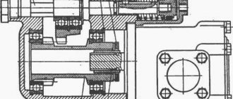
5 speed
The design of a five-speed gearbox in a MAZ includes such elements as:
- primary, secondary and intermediate shaft;
- rotating bearing;
- gears;
- crankcase, switch and rear cover;
- fasteners;
- container for oil liquid.
The mechanism that changes gears is located inside the vehicle. When the lever of the switching device changes its position, the articulated joint engages with the recess, which is located on one of the axes. At this moment, the end of the hinge is in rigid engagement with the fork device. The forks fit into the hole on the forward drive gear (gears No. 1, 2, 3, 4) or in the fifth gear position (reverse). A short circuit begins in the torque circuit, causing the secondary axis to begin its movement.
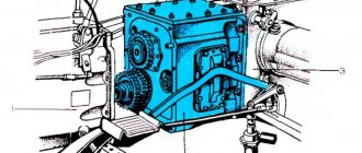
8 speed
The eight-speed gearbox (Gearbox-202) includes:
- crankcase;
- movable gears;
- intermediate shaft;
- constant mesh gears;
- drive shaft;
- splines;
- gear type rim;
- cover;
- driven shaft;
- reverse gear block;
- axial reverse mechanism.
After the vehicle moves and picks up the required speed, you can change gears in the following order: 4H-4B-5H. In order to activate the second speed, you need to wait until the crankshaft speed increases to 2000 rpm. This indicator can be monitored using a tachometer.
It is not recommended to start shifting gears at a lower number of crankshaft revolutions, otherwise the mechanism will fail.
In order to engage reverse, set the switch lever to the down position.
9 speed
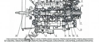
The design of the 9-speed gearbox 238 with a range-shifter includes the following parts and mechanisms:
- coupling housing;
- pad;
- gear shift fork;
- right shaft;
- reverse gear washer;
- lazy reverse gear;
- intermediate type roller shaft bearing;
- mounting bolts and nuts;
- spring washer;
- sealing ring;
- retaining ring;
- needle bearing;
- clutch fork bushing.
Before driving, you must disengage the clutch. Before moving off, you need to check the location of the lever; it must be lowered. Switching speed modes is carried out in several stages. At the first stage, it is recommended to use the following switching pattern: 1B-2B-3B. During further movement, you can switch to the pattern: 4H-5B-5H.
Not available:
| № | Part code | Name | Part Information |
| 5440A9-1703412 | Lever arm | Quantity 1 Model 5440A9 Group Gearbox Subgroup Gearbox control mechanism Part serial number 412 | Not available |
| 500-5001138-B | Sleeve | Quantity 1 Model 500 Group Cabin (Body) Subgroup Mounting of the cabin (body) Serial number of the part 138 Additionally Interchangeable with the part released earlier under the same number | Not available |
| 5336-1703544 | Sealant | Quantity 2 Model 5336 Group Gearbox Subgroup Gearbox control mechanism Part serial number 544 | Not available |
| 64221-1703323 | Plate | Quantity 2 Model 64221 Group Gearbox Subgroup Gearbox control mechanism Part serial number 323 | Not available |
| 64302-1703425 | Protective cap | Quantity 1 Model 64302 Group Gearbox Subgroup Gearbox control mechanism Part serial number 425 | Not available |
| 64221-1703646 | Clamp | Quantity 1 Model 64221 Group Gearbox Subgroup Gearbox control mechanism Part serial number 646 | Not available |
| 64221-1703724 | Clamp | Quantity 1 Model 64221 Group Gearbox Subgroup Gearbox control mechanism Part serial number 724 | Not available |
| 64221-1703814 | Roller axis | Quantity 1 Model 64221 Group Gearbox Subgroup Gearbox control mechanism Part serial number 814 | Not available |
| 64301-1703843 | A tube | Quantity 1 Model 64301 Group Gearbox Subgroup Gearbox control mechanism Part serial number 843 | Not available |
| 64301-1703841 | A tube | Quantity 1 Model 64301 Group Gearbox Subgroup Gearbox control mechanism Part serial number 841 | Not available |
| 64301-1703842 | A tube | Quantity 1 Model 64301 Group Gearbox Subgroup Gearbox control mechanism Part serial number 842 | Not available |
| 2ShSP20 | Bearing | Quantity 1 | Not available |
| 371690 | Bolt M10-6gх80 | Quantity 1 Coated uncoated | Not available |
| 220086 | Screw M5-6gx30 | Quantity 2 Coated uncoated | Not available |
| 231553 | Screw 2M4-6gx14 | Quantity 2 Coated uncoated | Not available |
| 250464 | Nut M5-6N | Quantity 2 Coated uncoated | Not available |
| 252006 | Washer 10 | Quantity 2 Coated uncoated | Not available |
| A-10-04-019 | Washer A.10.04.019 | Quantity 2 | Not available |
| 252003 | Washer 5 | Quantity 4 Coated uncoated | Not available |
| 252156 | Washer 10L | Quantity 1 Coated uncoated | Not available |
| 008-011-19-2-3 | Ring | Quantity 1 | Not available |
Change of oil
In order to change the oil in a MAZ gearbox, you must:
- Drive about 5-10 km by vehicle to warm up the old oil in the box. At elevated temperatures it becomes liquid and is easy to drain.
- 10-15 minutes after stopping the engine, place the vehicle on a lift or inspection pit.
- Remove the crankcase protective cover.
- Unscrew the plug and check the volume of oil fluid in the manual transmission.
- Check the gasket for wear and, if necessary, replace it with a new one.
- Replace worn filter elements.
- Open the drain hole and drain the oil into a prepared container.
- Fill with new oil fluid.
- Screw on the drain cap.
- Reinstall the clutch protective cover.
- Start the engine and check the oil level at various speeds.
How to remove and install the box
Disassembling the MAZ gearbox:
- Place the truck on a special platform.
- Remove batteries.
- Remove air filter elements.
- Disconnect the mudguards located in the engine compartment.
- Remove the front suspension cross member.
- Drain the gearbox oil.
- Disconnect the speed sensors, reverse switch.
- Remove the powertrain harness holder.
- Loosen the mounting bolts.
- Remove the electric starter from the coupling housing housing without disconnecting it from the wire.
- Unscrew the front and rear support mechanisms from the gearbox bracket.
- Disconnect the left support and disengage the input shaft.
- Remove the gearbox.
In order to put the KAMAZ box in place, you need to repeat all the steps in reverse order.