Gearbox design
It is necessary to study the design of this important element in more detail. It is a standard mechanical gearbox equipped with 5 stages, which allows you to select the optimal speed. It should be noted that thanks to the presence of 3 movable carriages at once, as well as a reduction gearbox, it is possible to double the number of gears.
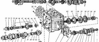
As the diagram of the YuMZ gearbox shows, the key elements of such a unit are the following parts:
- shafts - primary, intermediate, secondary, and also gear;
- the housing in which all the parts are located;
- gear mechanisms - driving and driven;
- gear lever;
- gear coupling;
- fasteners, clamps, brackets, latches.
YuMZ gearbox diagram
It should be noted that the housing of such an element is directly connected to the rear axle housing. All moving parts of the gearbox of this model are lubricated to prevent mechanical damage due to friction. Oil is poured into the device using a special hole located in the lid of the box.
In order for the unit to serve for a long time without any problems, it is necessary to change the oil in a timely manner and also monitor its level. For this purpose, 2 control plugs are placed on the gearbox housing - minimum and maximum oil level. To drain the oil, there is another hole located in the lower part of the unit, which is closed with a magnetic plug.
Leave a request in any form
YuMZ tractor gearbox
designed to change transmission gear ratios - obtaining different speeds, as well as changing the direction of movement of the tractor. In addition, the gearbox allows the diesel engine to operate with the tractor stationary and the clutch engaged.
Gearbox of tractors YuMZ-6KL and YuMZ-6KM
— mechanical, five-speed, without direct transmission, with three movable carriages and a reduction gear that doubles the number of gears. In the front compartment of the common housing of the gearbox and rear axle, the primary, secondary and intermediate shafts, as well as the gearbox shaft, are installed.
Gear shaft
mounted on an attached bracket attached to the right side of the housing. The constant mesh drive gear is installed on the splines of the input shaft and secured with a coupling bolt. The shaft with gear rotates on two roller bearings in a cup installed in the bores of the front wall and partition of the housing.
The outer races of both bearings are fixed at the outer ends between a split spring ring inserted into the annular recess of the cup and two pressure plates, which limits the axial movement of the input shaft assembly.
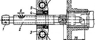
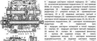
Gearbox of the YuMZ-6 tractor
1
- input shaft;
2
- coupling bolt;
3
- drive gear;
4
— pressure plates;
5 and 31
- glasses;
6
— intermediate roller;
7
— adjusting gasket;
8
— ball bearing;
9
— gear for engaging second and fourth gears;
10
— gear shift rollers;
11
— shift roller clamp;
12
— locking roller;
13
— locking roller lock;
14
- thrust;
15
- drawstring;
16
- switch;
17
— emphasis;
18
- axis;
19
— lever for engaging the PTO drive clutch lock;
2
0 — rocking chair;
21
- spring-loaded latch;
22
- stand;
23
— gear shift lever;
24
- bolt;
25
— gear shift column housing;
26
- fork;
27
— emphasis;
26
— gear for engaging first gear and reverse gear;
29
— secondary shaft;
30
- roller bearing;
32
— gear for engaging third and fifth gears;
33
— round nut:
34
— reverse drive gear;
35
- first gear drive gear:
36
- third gear drive gear;
37
— intermediate shaft;
38
— drive gear of fourth and fifth gears;
39
— drive gear of the second gear;
40
- thrust ring;
41
— oil drain plug;
42
— constant mesh gear;
43
— gearbox housing;
44
— PTO drive shaft.
Cup
at the same time serves as a seat for a ball bearing, which is the front support of the secondary shaft, installed coaxially with the primary shaft. A thrust ring is installed between the ball bearing and the spring ring, and the bearing is fixed in the cup with a retaining ring, which fits two protrusions simultaneously into the through cutouts of the cup and the annular groove on the outer race of the bearing. The bearing is secured to the secondary shaft journal with a special bolt. The bolt is secured with a flange washer.
Steel gaskets,
installed between the housing and the flange of the glass, serve to regulate the position of the drive gear of the main gear of the Yumz gearbox. The flange has two threaded holes for removing the cup when disassembling the gearbox.
Secondary shaft
manufactured as one piece with the main gear drive gear. At the rear, the secondary shaft rests on a roller bearing mounted in a cup. The glass is placed in the bore of the body and is fixed in it with a set screw and a lock nut. On the secondary shaft, on its splines, three movable gear carriages are installed, with the help of which one or another gear is engaged. The gear, which has one ring gear, is designed to engage first gear and reverse gear. The double ring gear is designed to engage third and fifth gears, and the pinion gear is designed to engage second and fourth gears. Each carriage at the rear end of the hub has an annular groove for the fork, with the help of which the carriage moves and the gear is engaged. The position of the carriages on the shaft in the longitudinal direction is determined by the position of the shift forks.
Intermediate shaft yumz gearbox
— hollow, rotates on two ball bearings installed in the lower part of the housing. Mounted on the intermediate shaft are: a reverse drive gear, a first-gear drive gear, a third-gear drive gear, a double-crowned drive gear of fourth and fifth gears, a second-gear drive gear and a constant-mesh idler gear. Moreover, the drive gears of all gears are installed on the shaft splines, and the intermediate gear, which has a bronze bushing, is installed on the cylindrical surface of the shaft.
In addition, the gear has an additional ring gear that matches the inner gear ring and a ring groove on the hub for the fork, which can be used to move it along the shaft.
All gears mounted on the splines of the intermediate shaft are tightly compressed between the thrust ring and the rear shaft bearing with a round nut, which is locked by bending its locking ring into the groove of the shaft.
Gear shaft
rotates in two ball bearings installed in the bracket. On the cylindrical part of the shaft there is a driven gear of the gearbox, which rotates on it on a bushing made of powder material, and on the splines of the shaft there is a gear coupling for engaging the gearbox and a drive gear. The gear coupling has an annular groove for the shift fork and can move along the shaft. When the gearbox is engaged, the gear coupling engages the ring gear of the gear hub. At the same time, the gear moves, and its additional ring gear disengages from the inner ring of the gear and is brought into engagement with the gearbox gear.
When the diesel engine is running, the clutch is engaged and the gear is disengaged, rotation from the diesel crankshaft is transmitted to the input shaft of the gearbox, and from it through the gear to the constant-mesh intermediate gear. If the gearbox is turned off, then the additional ring gear of the gear is in mesh with the internal ring gear of the gear, and the intermediate shaft, along with the gears sitting on its splines, also receives rotation.
If the gearbox is turned on, rotation is transmitted to the intermediate shaft from the gear through the gear, the gear coupling engaged with it, the shaft, the gearbox gear and the crown of the fourth gear gear, which is in constant engagement with it. To engage a particular gear, it is necessary to disengage the clutch, allow the intermediate shaft, which continues to rotate by inertia, to stop, move the corresponding carriage on the secondary shaft and engage its crown with the corresponding crown of the intermediate shaft gear.
When reverse gear is engaged, the gear receives rotation from the pinion through an idler gear mounted on the axle and rotating in two ball bearings.
In the required position, the rollers moved by the lever are held by clamps. The latches are located in the housing partition, in vertical holes located directly above the rollers. Each clamp is a cylindrical rod with a rectangular shank. The lower end of the clamp has a wedge shape. This end of the latch fits into one of the three wedge-shaped grooves on the shift shaft. The middle groove fixes the roller in a neutral position, corresponding to the gear being turned off, and the two outer ones determine it in positions corresponding to the engagement of the gears when moving the carriages forward or backward.
Clamps for rollers
they are pressed by springs, which are put on the shanks of the clamps and pressed by a special bar, pulled to the upper area of the body partition with two bolts. In the middle part of the bar there are four rectangular holes through which the shanks of the clamps pass. Due to the rectangular shape of the holes in the bar and the ends of the shanks, the clamps do not rotate. If there are clamps, moving any of the shift rollers becomes possible only when the clamp is completely released from the groove on the roller, further compressing the spring.
To reduce the end wear of the teeth, as well as to prevent incomplete engagement of the gears and their self-switching off during operation, there is a locking device in the gear shift mechanism. This device allows you to change gears only when the main clutch is completely disengaged.
The blocking device is designed as follows. On the gearbox cover directly above the shift roller clamps there is a clamp cover with a locking roller. The roller is connected by a rod to the clutch release mechanism. A groove is milled on the roller. When the clutch is engaged, the shaft is rotated so that the groove on it is located on the side of the latches. In this position, shifting gears is impossible, since the clamps, resting against the locking roller, cannot rise and release the shift rollers. They can only rise when the groove is above the clamps. The groove is in this position only from the moment the main clutch is completely disengaged until the PTO drive clutch is completely disengaged.
For ease of gear shifting, a stand is installed on the rocker, and a spring-loaded latch is installed on the lever. There is a slot in the rack in which the lever moves when selecting gears, and on its surface there is a sign - an indicator indicating the gears. The front end of the latch is fixed by the protrusion of the stand, and the rear end slides along the figured surface of the stand when the lever is moved.
To ensure safety, a locking mechanism is installed on the gear shift column, designed to prevent the diesel engine from starting when the gear is engaged.
Locking mechanism of the YuMZ-6KL tractor
consists of a switch mounted on the body of the gear shift column and a stop installed in the rocker and acting on the switch when the rocker moves. In the neutral position of the gear shift lever, the switch contacts are open. When the gear is engaged, the rocker tilts, the switch ball comes out of the cutout on the stop and closes the contacts. In this case, the magneto transformer winding of the starting motor is connected to ground, and its starting becomes impossible.
On YuMZ-6KM tractors, instead of a switch, a switch is installed, the contacts of which are closed in the neutral position of the gear shift lever. When the gear is engaged, the switch contacts open and break the diesel starter activation circuit. The position of the switch, ensuring its normal operation, is regulated by gaskets installed on its body.
The gearbox parts of the YuMZ tractor are lubricated by splashing oil located in the gearbox housing and rear axle. Wear products and other metal particles settle on the magnet of the plug that closes the drain hole in the housing.
Possible faults
Despite the high quality of assembly and the impressive service life of components, the gearbox of tractors of the YuMZ series often requires repair. As a rule, problems occur on units with an impressive mileage, the elements of which have a high degree of wear. Among the most typical breakdowns that occur most often, it is advisable to include:
- increased free play of the gear shift lever or their abrupt shutdown;
- excessive noise when the device operates;
- overheat;
- knocking noise when changing gears.
Such breakdowns can lead to serious problems, including failure of the entire unit, and therefore it is strongly recommended to begin repairing the YuMZ gearbox immediately after they are detected.
The gearbox requires careful care
Diagnosis of malfunctions should be carried out when switching the first reverse and forward gears.
During long-term operation, it is recommended to visually inspect the parts of the disassembled gearbox for defects.
Troubleshooting methods
The following breakdowns are possible:
- If the free play of the gear lever suddenly increases or they turn off spontaneously during operation, there is most likely a lack of proper contact in the gear mechanism. As a rule, this is caused by wear of the shift forks and carriages. In addition, the clamp springs could have failed and will need to be replaced to restore the device to working order.
- If overheating or unusual noise is detected, the condition of the shaft bearings should be checked, since their failure often leads to similar problems. To do this, you will need to dismantle the cabin floor, drain the oil from the gearbox, then open its cover and check the functionality of all shafts. Damaged items found during inspection will need to be replaced.
- A knocking sound when changing gears occurs when the gear mechanism breaks down due to wear of individual elements. To eliminate the malfunction, you will need to dismantle the cover and the dispensing unit, then find the broken part and replace it.
If you study the catalog of gearbox spare parts, you can conclude that servicing and repairing such a unit will not require significant costs, since all consumable items are affordable.
Be sure to read: Technical characteristics of the YaMZ-5344 engine