Design of the K-700 gearbox
Gearbox K-700 is a tractor unit with the help of which the following occurs:
- start and stop;
- forward and reverse speed adjustment;
- change in traction force on the hook;
- power transmission from the power unit to the power take-off mechanism;
- when towing - disabling the driving rear axle.
The gearbox of the K-700 tractor is mechanical, with the possibility of hydraulic control, with straight-cut gears of direct engagement. Includes 16 forward speeds and 8 reverse speeds.
Gearbox design of the K-700 tractor
Main components:
- drive shaft - responsible for shifting gears, made by stamping from alloy steel;
- crankcase – cast iron, made by casting, it houses the shafts and gearbox mechanisms; attached to the front half frame;
- gear part - includes shafts (distributing, intermediate, cargo) and pump drive;
- control drives are divided into mechanical (used to change the position of gear couplings) and hydraulic (used to bring synchronizer brakes into working condition).
Gearbox of the K-701 Kirovets tractor - part 1
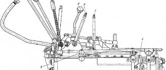
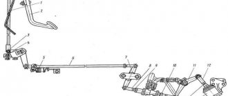
The gearbox, the general view of which is shown in Fig. 2.28, allows, along with changes in movement speed, to drive the pumps of the steering hydraulic system and the hitch from the drive wheels when towing the tractor. It also makes it possible to disengage the rear drive axle and transfer rotation to the power take-off shaft. The box crankcase consists of the upper 30 and lower 28 halves, a spacer and a pan 27. On the upper half of the crankcase there is a control drive bridge 2 with a parking brake lever 9 and a drain pedal 5; box hydraulic system filter; lever 13 and gear shift mechanism 14, which provides control of the clutches; hydraulic accumulator; switch levers 16 and 17
transfer shaft couplings and rear axle disconnection; synchronizer brakes 24 and 29 on the rocker 1 with lever 11 for engaging the cargo shaft and reverse clutches, as well as driver 15 for the control spool of the power take-off shaft drive.
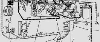
The gearbox part, illustrated in Fig. 2.29, consists of drive 1, intermediate 30, load 36 and transfer shafts, as well as pump drive shaft 32 with gear 33 and clutch 34. The drive three-bearing shaft (mounted on three bearings) has four clutches 11, 12, 23 and 27 , corresponding to gears I, II, III and IV With five spur gears. Gear 25 is the drive gear of the pump. Shaft 1 is hollow, it has two oil lines supplying oil to the clutches of gears I and IV. From the middle support 10 of the shaft, oil is supplied to clutches 11 and 23.
Rice. 2.28. General view of the tractor gearbox and the controls located on it: I - rocker; 2 — control drive bridge; 3 — traction compensator; 4 - sector; 5 — drain pedal; 6 — bar; 7 — parking brake lever button; 8 - roller; 9 — parking brake lever; 10 - dog; 11 — lever for turning on the load shaft couplings; 12 — spring;. 13 — gear shift lever; 14 — gear shift mechanism; 15 — driver of the PTO drive control spool; 16 — lever for engaging the transfer shaft clutch; 17 — rear axle release lever; 18, 19 — nuts; 20, 21 — thrust; 22, 23 — levers; 24 — brake synchronizer of first gear; 25, 26 — rollers; 27 - pallet; 28 — lower half of the crankcase; 29 — brake-synchronizer of fourth gear; 30 - upper half of the crankcase
Rice. 2.29. Gearbox part of a tractor gearbox
The intermediate shaft 30 is also three-bearing. There are seven gears installed on its splines, 13, 14, 15, 24, 26, 28 and 29. Of these, four are in constant engagement with the drive shaft friction gears, two (15, 26) are with gears that rotate freely on the load shaft, and Finally, gear 29 is the reverse drive gear.
The three-bearing load shaft is equipped with five cylindrical spur gears 35, 37, 38, 40, 44 and two toothed couplings 39 and 41. Gears 35 and 37 are located on the shaft splines and are constantly engaged with gears 21 and 22, which rotate freely on the transfer shaft. Gears 38, 40 and 44 have external and internal teeth; each of them is mounted on two ball bearings, and gears 29 and 44 (of the intermediate shaft) are connected through an intermediate gear 43. Toothed coupling 41, when moving along the shaft splines to the left, engages with gear 44, which ensures a change in the direction of rotation of the cargo and transfer shafts and tractor reverse. When moving along the shaft splines to the left, the gear coupling 39 engages with gear 40, and when moving to the right, with gear 38.
The transfer shaft has a clutch 20 and consists of two parts: a front axle drive shaft 18 and a rear axle drive shaft 17. The first is mounted on roller and ball bearings, and the second on needle and ball bearings. On shaft 18 there are gears 21 and 22, as well as a gear coupling 19, which in the left position is connected to gear 22. The rear axle is engaged by clutch 16, which ensures the connection of shafts 17 and 18 in the left position.
From Fig. 2.30, and it can be seen that the pump drive shaft, together with two gears 3 and 6 located on it and a gear coupling 4, is installed on the upper half of the crankcase parallel to the drive shaft of the gearbox. From the latter, through gear 5, which is meshed with gear 6, through gear coupling 4, the pump drive shaft 2 receives rotation. When towing the tractor, clutch 4 engages with gear 3, which is constantly in mesh with the reverse intermediate gear 1. Thanks to this, rotation is transmitted to the pump drive shaft. The gearbox hydraulic system pump rotates from the drive shaft through the bevel gear 7 and the roller 8. The tachospeedometer is driven through a worm gear from the pump drive shaft and roller 31 (see Fig. 2.29).
Gearbox clutches with steel discs and hydraulic control are shown in Fig. 2.20, b. They are installed on the drive shaft of the box and are structurally similar to each other.
Rice. 2.30
Rice. 2.31
Each clutch consists of driving and driven parts and an activation mechanism. The leading parts of the clutch are the driving or inner drum 10, the driving friction disk 18, the pressure disk 16 with springs 11 and cups. The driven part of the clutch is formed by the driven or outer drum 21 and the driven friction disk 19. The activation mechanism includes the middle right disk
14 with sealing rings 12 and 13, as well as cast iron sealing rings. 22 with cuffs 9 and a ring 23. The leading parts of the clutch are rigidly connected to the drive shaft 15, rotating at the speed of the engine shaft; their driven parts are connected to freely rotating gears.
The clutch is engaged due to the oil pressure entering the space (booster) between the middle and pressure disks. The latter compresses the pack of friction disks, and the torque from the drive shaft
15 is transmitted to a gear attached to the driven outer drum 21, and then goes to the intermediate shaft. Part of the oil through the hole in the pressure disk enters the cavity of the inner drum 10 and then through the holes in it goes to lubricate the friction disks. When the clutch is turned off, springs 11 return the pressure plate to its original position. To ensure normal operation, there are o-rings 17 and 20.
The hydraulic system of the gearbox, shown schematically in Fig. 2.31, has a hydraulic pump 18, filter 2, gear shift mechanism 9, bypass valve 3, power take-off shaft (PTO) spool 6, drain spools 7 and 8 for gear shifting and synchronizer brakes, bypass valves 10, 11 and 12, hydraulic accumulator 13, oil radiator 25, pressure reducing valve 4, lubricant pressure limiting valve 5, oil pressure sensor and indicator 14, oil filler tank 15, breather, piping and hose system. It is designed to turn on clutches 16, 19, 20, 21, 22, synchronizer brakes 1, lubrication and cooling of the drive shaft 23, gear part 24 of the gearbox, pump drive gearbox and power take-off shaft coupling.
The oil, partially purified while the engine is running in a coarse mesh intake filter 17 with a magnet installed in the drain plug, flows to the pump 18, and from it to the gearbox filter 2. There it is cleaned of wear products and enters the pressure reducing valve 4, which provides maintaining the required pressure in the clutch booster of the engaged gear (or in the synchronizer brakes) and in the clutch of the PTO coupling (when it is in the engaged position). From valve 4, part of the oil is supplied to the gear shift mechanism, and from it to the gear booster, synchronizer brakes 1 or to the PTO clutch. The rest of it often goes through holes in the pressure reducing valve body to lubricate the gearbox, pump drive gearbox, PTO coupling and into the oil cooler. The pressure in the lubrication system is limited by a valve installed in the upper cavity of the crankcase, which acts as a radiator safety valve, which is adjusted to a pressure of 220 kPa.
The gear shift mechanism shown in Fig. 2.32, has a body 10, a driver 5, a cover 2, a lever 6, a rack 3 with a lock 4 and spools for the power take-off shaft, drain 11, gear shift and synchronizer brake activation 9, as well as changeover spools 1, 7, 12. Spool 8 , connected to rail 3, has six fixed positions. At the first extreme rear position of the rack, it supplies oil to the synchronizer brakes, at the second, oil is drained from the synchronizer brakes, at the third to sixth positions, oil is supplied to the boosters of the four gears engaged. A rapid decrease in pressure in the clutches, synchronizer brakes and hydraulic accumulator, as well as the creation of a “smooth approach” mode, is ensured by drain spool 11. Being a locking device, it does not allow engaging first gear before pressing the drain pedal. Charging and discharging the hydraulic accumulator to the booster during the transition from one gear to another is ensured by changeover spools 1,7 and 12. The mechanism has a latch 13 with a stop.
Rice. 2.32. Gear shift mechanism
content .. 11 12 18 ..
Frequent breakdowns and repair features of the K-700 gearbox
Most breakdowns of the tractor gearbox are associated with wear of individual parts. Repair of a gearbox on a K-700 includes disassembling the unit, washing, eliminating defects and replacing worn-out spare parts, assembly and running-in, and checking pressure.
Main possible breakdowns and solutions:
| External manifestation | Possible reasons | Type of repair |
| Difficulty switching gears | Damage or wear of clutch or synchronizer teeth | Replacement |
| Decrease in tractor speed in one gear | Oil leak | Fix the leak |
| Insufficient oil level in the crankcase | Top up | |
| Worn clutch discs | Replacement | |
| Spontaneous gear disengagement while driving | Worn clutch teeth, shaft bearings, rod clamps | Replacement |
| Tractor jerks at start and extraneous knocks | Oil intake screen clogged | Cleaning |
| Slow inclusion or non-inclusion of ranges in the range multiplier | Membrane wear | Replacement |
| Damage to the sealing rings of the working cylinder | Replacement | |
| Increased noise | Worn or broken gear teeth or bearings | Replacement |
| Low oil in the crankcase | Top up to the control hole | |
| Air intake through breather | Wear of the inlet valve sealing rubber | Replacement |
| Poor pushrod fit | Replacement | |
| Leaking from tractor axles | Large amount of oil | Drain off excess |
| Breather contamination | Remove and wash |
Causes of malfunction of the K-700 gearbox
Adjusting the gearbox of the K 700 tractor
After repairing the K-700 gearbox, running-in is performed on a special stand in the following sequence:
- Pour engine oil into the gearbox housing to the level of the upper inspection hole.
- Rotate the drive shaft at 900 rpm for one minute, add oil if necessary.
- Run in neutral mode for 5 minutes at a speed of 900 rpm, then sequentially in each of the 4 gears for 2 minutes.
- At the end of the check, close the technological openings of the gearbox with plugs.
Adjusting the spool drive of the gear shift mechanism on the K-700
During the running-in, the system performance indicators are checked and adjustments are made to the K-700 gearbox:
- oil pressure supplied to the lubrication is not less than 0.05 MPa;
- oil pressure supplied to the synchronizer brake and power take-off mechanism – 0.85 MPa;
- smooth operation of gears without extraneous noise;
- no leaks from connections and gaskets.
The gearbox is the most important component of the tractor, responsible for starting, moving and stopping. If signs of malfunction of the K-700 gearbox appear, it is necessary to perform a full diagnosis of the unit. Ignoring the problem can lead to spontaneous start, change in direction and speed of movement, which leads to an emergency situation.
Not available:
| № | Part code | Name | Part Information |
| 700-1724023-2 | Clamping bolt | Quantity 4 Model 700 Group Gearbox Subgroup 1724 Serial part number 023 Additionally Not interchangeable with a part previously released under the same number | Not available |
| 2256010-1716000 | Filter | Quantity 1 Group Cardan shafts Subgroup 2256 Serial part number 010 Additionally Not interchangeable with a part previously released under the same number | Not available |
| 2256010-1700120-01 | Pipe | Quantity 1 Group Cardan shafts Subgroup 2256 Serial part number 010 Additionally Not interchangeable with a part previously released under the same number | Not available |
| M8x35 | Bolt | Not available | |
| 700A-3400070 | Sleeve | Quantity 1 Model 700A Group Steering control Subgroup Steering control assembly Part serial number 070 | Not available |
| 2256010-3420000 | safety valve | Quantity 1 Group Cardan shafts Subgroup 2256 Serial part number 010 Additionally Not interchangeable with a part previously released under the same number | Not available |
| 700A-1724160-3 | Pipe | Quantity 1 Model 700A Group Gearbox Subgroup 1724 Serial part number 160 Additionally Not interchangeable with a part previously released under the same number | Not available |
| 018-022-25-1-3 | Ring | Quantity 1 | Not available |
| NSh10-3-A | Pump | Quantity 1 | Not available |
| M8x30 | Bolt | Not available | |
| 2256010-1700019 | Pad | Quantity 1 Group Cardan shafts Subgroup 2256 Serial part number 010 Additionally Not interchangeable with a part previously released under the same number | Not available |
| 2M10x40 | Hairpin | Not available | |
| 2256010-1700022 | Lid | Quantity 1 Group Cardan shafts Subgroup 2256 Serial part number 010 Additionally Not interchangeable with a part previously released under the same number | Not available |
| 2256010-1700018 | bracket | Quantity 1 Group Cardan shafts Subgroup 2256 Serial part number 010 Additionally Not interchangeable with a part previously released under the same number | Not available |
| 2256010-1700021 | Pad | Group Cardan shafts Subgroup 2256 Serial part number 010 Additionally Not interchangeable with a part previously released under the same number | Not available |
| 700A-0017106 | Cap | Quantity 1 Model 700A Subgroup Gearbox Part number 106 | Not available |
| 700A-0017105 | Pad | Quantity 1 Model 700A Subgroup Gearbox Part number 105 | Not available |
| 700A-0017170 | Pipe branch | Quantity 1 Model 700A Subgroup Gearbox Part number 170 | Not available |
| 700-1701275 | Pad | Quantity 1 Model 700 Group Gearbox Subgroup Gearbox Part serial number 275 | Not available |
| 2256010-0017120 | bracket | Quantity 1 Group Cardan shafts Subgroup 2256 Part number 010 | Not available |
| M10x25 | Bolt | Not available | |
| 42x55-1.5 | Sleeve | Note 2x0.08m | Not available |
| 700-1701251-1 | Pad | Quantity 1 Model 700 Group Gearbox Subgroup Gearbox Serial part number 251 Additionally Not interchangeable with a part previously released under the same number | Not available |
| 700A-1700120 | Pipe | Quantity 1 Model 700A Group Gearbox Subgroup Gearbox assembly Part serial number 120 | Not available |
| M10x20 | Bolt | Quantity 4 | Not available |
| 700A-0017098-01 | Pad | Quantity 12 Model 700A Subgroup Gearbox Part number 098 | Not available |
| 700A-0017098-02 | Pad | Quantity 8 Model 700A Subgroup Gearbox Part number 098 | Not available |
| AKSS-220M | Shock absorber | Quantity 4 | Not available |
| М22х65-88-45Х | Bolt | Quantity 4 | Not available |
| М14х45-88-45Х | Bolt | Quantity 8 | Not available |
| 2765015-1700000 | Gearbox assembly | Quantity 1 Group Saddle device Subgroup 2765 Serial part number 015 Additionally Not interchangeable with a part previously released under the same number | Not available |
| 700-1724045 | Clamping bolt | Quantity 1 Model 700 Group Gearbox Subgroup 1724 Part number 045 | Not available |
| Hairpin M10x55 | Hairpin | Quantity 1 Note 10x55 | Not available |
| 2256010-1700140 | Pipe | Quantity 1 Group Cardan shafts Subgroup 2256 Serial part number 010 Additionally Not interchangeable with a part previously released under the same number | Not available |
| 2256010-3800090 | Sleeve | Quantity 1 Group Cardan shafts Subgroup 2256 Serial part number 010 Additionally Not interchangeable with a part previously released under the same number | Not available |
| 20 | Washer | Quantity 1 | Not available |
| 700A-3800011-2 | bracket | Quantity 1 Model 700A Group Devices Subgroup 3800 Serial part number 011 Additionally Not interchangeable with a part previously released under the same number | Not available |
| 19-3829010 | Oil pressure sensor | Quantity 1 Model 19 Group Instruments Subgroup Oil pressure indicator sensor Part serial number 010 | Not available |
| M20x1.5 | screw | Not available | |
| 2256010-1700016-1 | Pad | Group Cardan shafts Subgroup 2256 Serial part number 010 Additionally Not interchangeable with a part previously released under the same number | Not available |
| 700-1701133-1 | Pad | Model 700 Group Gearbox Subgroup Gearbox Serial part number 133 Additionally Not interchangeable with a part previously released under the same number | Not available |
| 700-1716107-2 | Valve | Model 700 Group Gearbox Subgroup 1716 Serial part number 107 Additionally Not interchangeable with a part previously released under the same number | Not available |
| 2765010-1746000-2 | Valve | Group Saddle device Subgroup 2765 Serial part number 010 Additionally Not interchangeable with a part previously released under the same number | Not available |
Preventive measures
Necessary preventive measures:
Gearbox part of the K-700 gearbox
- change the oil on time;
- monitor the pressure in the gearbox and prevent a decrease in performance when idling;
- regularly clean the oil passages;
- do not use worn or deformed parts, replace them;
- use original spare parts for the K-700 tractor;
- Wash the filters of the hydraulic power transmission control system.
It is important to remember that the K-700 gearbox is a complex system, and any unqualified intervention can lead to complete failure of the entire unit. The service life of the tractor gearbox is influenced by the type of oil used - it is necessary to choose the appropriate brands. If it is better to entrust complete repairs to professionals, then you can fill and change lubricants in the box yourself.
Related video: K-700 gearbox after repair
Publications on the topic
Features of the MTZ-82 gear shift scheme
Features of the YaMZ-236 gearbox design
What is the best oil to use for a chainsaw chain?