ELECTRICAL EQUIPMENT OF THE UAZ-469 CAR
The electrical equipment of the car is 12-volt, the wiring is single-wire, the negative pole of the current sources is connected to ground.
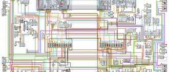
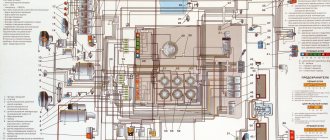
The electrical circuit diagram is shown in Fig. 103.
Rice. 103. UAZ-469 electrical equipment diagram (UAZ-469 electrical diagram): 1 - front lamp; 2 - headlight; 3 — connecting panel; 4 — side turn signal repeater; 5 — turn signal switch; 6 — heater electric motor; 7 — lighting lamp under the hood; 8 — sound signal; 9 — spark plug; 10 - distributor; 11 — ignition coil; 12 — starter relay; 13 — switch, 14 — horn button; 15 — water temperature sensor in the cylinder block; 16 — sensor of the water temperature warning lamp in the radiator; 17 — emergency oil pressure sensor; 18 — oil pressure sensor; 19 — hydraulic drive warning lamp switch; 20 - voltage regulator; 21 - generator; 22 — starter; 23— indicator lamp; 24 — water temperature control lamp; 25 — oil pressure control lamp; 26 — control lamp for hydraulic brakes; 27 — fuse block; 28 — electric motor for windshield washer; 29 — windshield wiper motor; 30 — rechargeable battery; 31 — fuel level indicator; 32 — water temperature indicator; 33 — oil pressure indicator; 34 - ammeter; 35 — speedometer: 36 — wiper and washer switch; 37 — ignition switch; 38 — plug sockets; 39 — ground switch; 40 — control lamp for high beam headlights; 41 - thermal fuse; 42 — central light switch; 43 — foot light switch; 44 — alarm switch; 45 — brake signal switch; 46 — direction indicator switch; 47 — fuel tank switch; 48 — cabin light switch; 49 — reverse light switch; 50 — fuel level indicator sensors; 51 — cabin lighting; 52 — trailer socket; 53 — rear lamp; 54 — reversing lamp; 55 — license plate light.
Symbol for wire colors on the UAZ-469 diagram: F - purple; F - yellow; 3 - green; K - red; G - blue; Ch - black; Kch - brown; O - orange; C - gray.
The electrical circuit of the UAZ-469 combines all the devices and instruments used in the car. If malfunctions occur in the system, full operation of the car can cause difficulties for the car owner, so all breakdowns must be promptly repaired. You can learn more about malfunctions, as well as wiring prevention, from this material.
What is included in the electrical circuit?
The above is a form of electrical wiring diagram.
Regardless of which UAZ you use - old or new model - the main components of the electrical network are as follows:
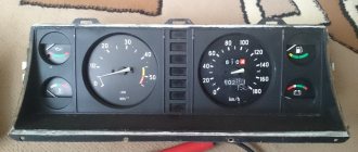
- Dashboard. It displays the main sensors and indicators indicating that a particular device is turned on. Tidying allows the driver to know at what speed he is moving, how much fuel is left in the tank, what the crankshaft speed is and what the engine temperature is. In addition, there are many lights installed on the tidy that light up synchronously with the switching on of certain devices.
- Accumulator battery. The battery is an integral element of any car; it allows you to power the vehicle’s equipment when the engine is turned off, and also helps the ignition system in starting the power unit. If the battery is discharged, you will not be able to start the engine in the traditional way - you will either need to recharge it or try to start it with a pusher.
- A generating device, the failure of which will also make it impossible to start the engine. This unit provides voltage to all devices and devices used in the car while driving.
- Fuse block. This device contains all the safety devices designed to protect electrical circuits and devices from overvoltage. If there is a power surge in the network, then the main blow will be taken by the fuse (author - Ben & Ice Video Master channel).
Prevention measures
Basic measures to prevent electrical system malfunctions:
- Regularly check the condition of the wire tips installed on the battery terminals. Clean parts from oxides and dirt.
- Wipe the battery case from dust. If a serviceable battery is used, it is necessary to clean the ventilation ducts and bring the electrolyte density to normal. Periodically recharge the device from the charger.
- During long periods of inactivity, disconnect the battery using the standard disconnect switch.
- The wiring harness should not bend or rub against sharp edges of the body panels. If damage to the insulation is detected, restore the protection with insulating tape or replace the wiring section. Protect the bend points with special sleeves.
- If a fuse blows, determine the cause of the failure. It is prohibited to carry out repairs by installing reinforced elements designed for increased current.
- Monitor the condition of the starter by periodically cleaning the rubbing elements from dirt and lubricating them with Litol-24. Check the axial clearance of the rotor, which should be within 1 mm, and the tightness of the bolts securing the unit to the engine crankcase. Electrical contacts must be cleaned of carbon deposits using a file.
- Clean the distributor slider from dust and oil using a rag and clean gasoline. At the same time, lubricate the rotor bushing (a few drops are applied under the removed felt). High-voltage wires must be installed tightly in the seats. If moisture gets on the elements, wipe them with a clean and dry cloth.
- Do not overuse the emergency vibrator, which has a service life of about 30 hours. When switching on the backup ignition, deactivate the carburetor economizer.
- Check the fastening of devices in the instrument cluster, replacing burnt parts.
Common faults
As for breakdowns in the electrical wiring of the Ulyanovsk Automobile Plant product, they are as follows:
- Battery low. As we have already reported, without a battery, normal operation of the motor will be impossible, and the same applies to electrical equipment. Battery discharge can occur for various reasons. Due to evaporation of the electrolyte or its leakage as a result of damage to the battery case, damage to the plates inside the structure, or their short circuit. Typically, such problems are caused by wear and tear of the device or its improper operation.
- Failure of the safety device. Its burnout can occur as a result of wear or a power surge. Before installing a new fuse, you need to test the circuit to make sure there are no surges. If they do occur, then the cause must be determined and eliminated, otherwise the problem will recur.
- Broken wire. This problem is relevant not only for UAZ, but also for other cars. To prevent breaks, wires should be laid away from moving parts of the body.
- There is no contact with the device. This usually occurs as a result of a broken wire, but if it is intact, then the problem lies in the contact. The end of the wire could simply come off or oxidize. Oxidation is one of the main problems in domestic cars.
- Generator failure. The design of the generator unit itself is quite complex, so there can be many problems in its operation. If the generator itself works, but incorrectly, first of all it is necessary to diagnose its belt - it may be overtightened or tensioned too loosely, in which case adjusting it will solve the problem.
Two names for one model
The thing is that from 1945 to 1966 there was an industry classification of vehicles, according to which:
- Each car plant was assigned a code consisting of capital letters of the full name;
- Car factories were assigned a certain digital range, which they could use for the models they produced.
For reference: the Ulyanovsk Automobile Plant has been assigned the letter code UAZ, and the range is from 400 to 499. Accordingly, all models produced and advertised in the video must be designated in this way.
New requirements
When a new classification of vehicles was adopted in 1966 (industry standard - OH 025270-66), the essence of which was to standardize digital designations, the process of replacing the names of existing vehicles turned out to be quite complicated:
- Due to the impossibility of simultaneously replacing all documentation;
- Due to the mentality of producers and consumers, therefore, the replacement process lasted more than 30 years.
Index decoding
The civilian version of the car “459B”, according to the new classification, received the digital index 31512, where:
- The first digit indicates the vehicle class, determined by engine displacement and vehicle weight. In relation to the model, this is the number “3” weighing up to 1.5 tons and working volume up to 2.5 liters;
- The second digit of the index indicates the type of vehicle. Number “1” – passenger car;
- The third and fourth digits of the index are assigned by the automaker. As a rule, they indicate an in-plant designation;
- The fifth digit indicates the modification. In this case, UAZ modified the “459” model, which, according to the new requirements, should be numbered as 3151. Accordingly, the modified car receives the index 31512.
And since the vehicle is produced and operated much longer than this period, the wiring diagram of the UAZ 31512 is identical to “459B”.
Caution: in the process of modernizing cars, designers almost always make changes to electrical circuits. Accordingly, the electrical wiring of the UAZ 31512 will differ from the previous version. This must be taken into account when servicing or replacing it.
electrical circuit in its simplest form
The good old UAZ-469 is one of the simplest cars. As if assembled from a children's construction set, it is by no means replete with any frills or bells and whistles. Instead of air conditioning, there is the ability to remove the soft roof, and instead of power packages, there is a complete absence of anything that can be controlled using this package. However, there is electrical wiring on this car. Although the same electrical circuit for the UAZ-469 ignition is implemented in the simplest way.
Starter
On a UAZ-469 car, the starter is connected almost directly, through the ignition switch and relay. There is simply no more electronics in the ignition circuit. Even in the more modern Hunter, which not every car enthusiast can distinguish from a UAZ-469 in appearance, the electrical circuit is much more complex. The control pulse from the ignition relay goes directly to the generator, and all wiring goes through the fuse block. The 469 used fuses that only went to the lights and generator. In general, an experienced UAZ-469 owner simply does not need an electrical circuit. You can understand this car in a few minutes.
Peculiarities
It is worth noting several interesting features of this car. which will be of interest to those who get behind the wheel of the legendary UAZ for the first time. For example, the light switch of this car is located at the feet in the form of a special pedal. We won’t judge how convenient it is while driving; we’ll leave it to those who have already driven a UAZ-469. The wiring diagram of this car is also full of many interesting features that are elegant in their simplicity. Oil level and pressure sensors, for example, went directly to the dashboard and emergency indicator, bypassing the fuse box and other elements. This allows you to literally repair your car “on your knees”, from anywhere. It’s not for nothing that the 469th is still valued by the military. When repairing a UAZ-469, they don’t even need an electrical circuit.
Characteristics
Despite its simplicity, the UAZ-469 already in those years had an autonomous heater, two fuel tanks and excellent cross-country ability. It was possible to overcome fords, obstacles and bad roads on this SUV without any modifications, but today tuning of various UAZs, including the 469 model, is becoming increasingly popular. Amateurs equip cars with larger wheels with mud tires, lift the car and install more powerful engines. True, with the latter option, all the simplicity of the design fades into the background, because you have to completely redo the entire electrical wiring of the cars. Nevertheless, the popularity of the car is only growing.
Generator belt
The drive from the engine crankshaft to the generator set pulley is a flexible belt drive. The belt is a standard size; it is inserted into the pulley grooves on the engine shaft and on the generator itself. The belt tension is achieved by adjusting the generator bracket on the engine.
The G250P2 generator is mounted on a bracket to the UMZ-417 engine block on the right side. It is driven into rotation by a V-belt from the crankshaft pulley. UAZ is usually equipped with a UAZ 469 generator belt, the size of which is 1,275 mm. Belt model 6 RK 1275. The abbreviation means: 6 strands, RK - poly-V-ribbed, length 1,275 millimeters. This is the size of the alternator belt for UAZ 469 engine 417.
Photo 6: UAZ 469 alternator belt (Source: Yandex.Pictures)
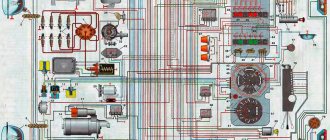
UAZ-31512 diagram – Electrical equipment diagrams – UAZ
Electrical diagram of the UAZ-31512 car:
- Front lamp
- headlight
- Sound signal
- Generator
- Lamp under the hood
- Coolant temperature indicator sensor in the cylinder block
- Sensor for warning light of emergency overheating of coolant in the radiator
- Sensor for warning light of hydraulic brake system emergency condition
- Oil pressure indicator sensor
- Oil pressure warning light sensor
- Control microswitch EPHH
- Spark plug
- Sensor-distributor
- Windshield washer motor
Electrical diagram of the UAZ-31512 car: https://uaz.service-manual.company/shemy-elektrooborudovaniya/shema-elektrooborudovaniya-avtomobilya-uaz-31512/
Generator G250P2
Photo 3: Generator G250P2 (Source: Yandex.Pictures)
- Bearing cap
- Sleeve
- Rear ball bearing
- Conclusion "Ш"
- Brush holder
- Brushes
- Stator winding
- Stator
- Rotor winding
- Rotor
- Front cover
- Impeller
- Pulley
- Key
- Sleeve
- Front ball bearing
- Front cover
- Bearing cap
- Sleeve
- Rotor shaft
- Slip rings
- Rectifier block
- Back cover
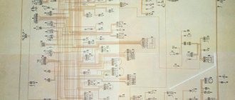
Wiring diagram of UAZ-3303 onboard (tadpole) – Wiring diagrams of UAZ –
1 – front lamp;
3 – heater fan electric motor;
4 – sensor for warning lamp of emergency condition of hydraulic brake drive;
5 – sound signal;
6 – washer motor;
7 – cabin light switch;
8 – cabin lighting;
9 – warning lamp for turning on the parking brake system;
10 – switch for the parking brake system warning lamp;
11 – windshield wiper motor;
12 – switch for the electric motor of the windshield wiper and washer;
14 – signal lamp for turning on the high beam headlights;
Glass cleaning
The windshield of a UAZ 31512 car is cleaned with electrically driven brushes. The wiper motor has two modes. The windshield wiper system includes an electric washer motor. The system is controlled by a combination switch.
ATTENTION: The electrical diagram includes a socket for connecting trailer wiring.
From the above it follows that the UAZ 31512 equipment consists of several electrical circuits. The wiring is made with multi-colored wires. This makes the repair procedure easier if there is a color scheme.
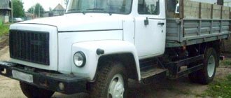
The main command vehicle of the armed forces - this is how the UAZ 469 SUV can be described. And indeed, having replaced the GAZ-69 in 1972, it secured this honorable duty for many years, proving the correctness of the design and main components with its endurance and reliability.
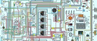
Electrical diagram of the UAZ-31512 car | AUTOFIZIK.RU / auto repair
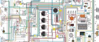
1 — front light; 2 — headlight; 3 — sound signal;
4 — connecting block; 5 — side direction indicator; 6 — additional resistance; 7 — heater switch; 8 — heater fan electric motor; 9 — engine compartment lighting; 10 - generator; 11 — direction indicator relay; 12 — spark plugs; 13 — ignition coil; 14 — starter relay; 15 - starter; 16 — ignition distributor sensor; 17 - switch; 18 — battery; 19 — electric windshield washer; 20 — windshield wiper; 21 — “mass” switch; 22 — portable lamp socket; 23 - emergency vibrator; 24 - fuse block; 25 — oil pressure indicator sensor; 26 — coolant temperature sensor; 27 — coolant overheat warning lamp sensor; 28 — emergency oil pressure warning lamp sensor; 29 — switch for the emergency signal lamp of the hydraulic brake drive; 30 — parking brake warning lamp switch; 31 — brake signal switch; 32 — voltage regulator*; 33 — foot light switch; 34 — parking brake warning lamp; 35 — signal lamp of direction indicators; 36 — warning lamp for emergency condition of the hydraulic brake drive; 37 — horn switch; 38 — carburetor microswitch; 39 — electromagnetic valve of the EPHH system; 40 — block of the EPHH system; 41 — windshield wiper and washer switch; 42 — speedometer; 43 — warning lamp for emergency oil pressure; 44 - warning lamp for coolant overheating; 45 - central light switch; 46 — alarm switch; 47 — fuel level indicator; 48 — coolant temperature indicator; 49 — oil pressure indicator; 50 - ammeter; 51 — signal lamp for high beam headlights; 52 — interior lamp; 53 — interior lamp switch; 54 — direction indicator switch; 55 — fuel level indicator sensor; 56 - thermal (bimetallic) fuse; 57 — fuel tank sensor switch; 58 — ignition switch; 59 — reverse light switch; 60 — rear light; 61 — trailer socket**; 62 — reversing light; 63 — license plate light.
* On vehicles with generator types 665.3701, 161.3771, G700A.30 and 957.3701, an external voltage regulator is not installed.** Installed on some vehicles.
Note. On cars of recent years of production, the ammeter is replaced by a voltmeter, the brake warning light switch is replaced by a low brake fluid level sensor, and the high beam headlight warning light is placed on the dashboard.
Power supply and start of the power unit
The engine is started by an electric starter. It is an electric motor. The starter is equipped with a retractor relay. It is used to turn on the device and engage the drive gear with the motor flywheel. The starter is turned on remotely using the ignition switch.
Electrical supply is necessary for the normal operation of the internal combustion engine. This includes:
- High voltage coil;
- Distributor;
- Spark plug;
- Idle speed solenoid valve;
- Forced idle switch;
- Idle speed control unit;
- Switch.
Electrical equipment - UAZ-469 diagram
The UAZ-469 electrical equipment diagram is shown in Fig. 103.
Rice. 103. UAZ-469 electrical equipment diagram (UAZ-469 electrical diagram): 1 - front lamp; 2 - headlight; 3 — connecting panel; 4 — side turn signal repeater; 5 — turn signal switch; 6 — heater electric motor; 7 — lighting lamp under the hood; 8 — sound signal; 9 — spark plug; 10 - distributor; 11 — ignition coil; 12 — starter relay; 13 — switch, 14 — horn button; 15 — water temperature sensor in the cylinder block; 16 — sensor of the water temperature warning lamp in the radiator; 17 — emergency oil pressure sensor; 18 — oil pressure sensor; 19 — hydraulic drive warning lamp switch; 20 - voltage regulator; 21 - generator; 22 — starter; 23— indicator lamp; 24 — water temperature control lamp; 25 — oil pressure control lamp; 26 — control lamp for hydraulic brakes; 27 — fuse block; 28 — electric motor for windshield washer; 29 — windshield wiper motor; 30 — rechargeable battery; 31 — fuel level indicator; 32 — water temperature indicator; 33 — oil pressure indicator; 34 - ammeter; 35 — speedometer: 36 — wiper and washer switch; 37 — ignition switch; 38 — plug sockets; 39 — ground switch; 40 — control lamp for high beam headlights; 41 - thermal fuse; 42 — central light switch; 43 — foot light switch; 44 — alarm switch; 45 — brake signal switch; 46 — direction indicator switch; 47 — fuel tank switch; 48 — cabin light switch; 49 — reverse light switch; 50 — fuel level indicator sensors; 51 — cabin lighting; 52 — trailer socket; 53 — rear lamp; 54 — reversing lamp; 55 — license plate light.
Historical reference
Traditionally, the UAZ 469 was produced in two versions:
- Cargo-passenger version - 7 seats and 100 kg of luggage;
- Commander version - 2 seats for passengers and 600 kg of luggage.
For reference: regardless of the version, the UAZ 469 can tow a trailer with a total weight of 850 kg.
Industry standard 1945
According to the old vehicle classification system, in force since 1945, the UAZ 469 was produced under this name, using an alphanumeric name:
- The letter abbreviation UAZ stood for Ulyanovsk Automobile Plant;
- 469 is a serial factory index assigned by the enterprise itself to its models and developments.
For reference: according to the industry standard of 1945, each automobile plant was assigned a specific numbering. For MZMA, which produced Moskvich 408 and 412, these are numbers from 400 to 449, for the Ulyanovsk Automobile Plant these are numbers from 450 to 484, etc.
1966 Industry Standard
Although at the time of the release of the UAZ 469 (1972) a new industry classification system was adopted (industry standard OH 025270-66), the car plant continued to use the name according to the old standard.
However, in 1985, the automaker was forced to change its name in accordance with current requirements:
- the car was assigned a four-digit number - 3151;
- According to the new system, the car can be called in the documentation as UAZ 3151.
For reference: industry standard OH 025270-66 prescribes determining the type of vehicle by engine displacement, length and weight. The first digit indicates the class of the car, the second – the type (truck or passenger car), the third and fourth – the factory model index.
The car plant named all further modifications and new models in accordance with current standards. In particular, the UAZ Patriot, which appeared in 2005, according to the industry classification, received the “correct” designation - UAZ-3163. For greater identification, the factory instructions contained both names.
UAZ ignition system – Ignition – Vehicle
Currently, non-contact combustion systems are used. Of course, they are made on an electronic basis. The contacts are no longer able to ensure reliable engine operation at 6000 rpm. At this speed, the contacts no longer have time to close. The spark power drops. Such problems do not occur in contactless ignition systems. In previous issues, the sensor-distributor assembly was described, in old books called a distributor. The spark discharge energy is one and a half to two times higher than in battery ignition systems. Thanks to this, the car starts easier, has less toxicity and fuel consumption. The engine can develop a high rotation speed. That’s all the difference, and a fundamentally new unit – the commutator. It’s worth talking about it, since the quality of work depends on the brand of the switch. As an example, let's consider the electronic ignition systems of cars of two brands - GAZ and UAZ.
The switch is an amplifier of the electrical signal from the sensor and at the same time it provides power to the ignition coil. As soon as a current pulse arrives from the sensor, the commutator stops supplying current to the primary winding of the coil. In this case, a high-voltage current pulse appears in the secondary winding. At the same time, a spark jumps at the spark plug, igniting the mixture of gasoline and air.
The ignition system of UAZ vehicles consists of a distributor sensor (distributor) 33.3706 or 19.3706, an ignition coil B-116, an additional resistor 14.3729 (variator), a switch 13.3734, spark plugs A11, and an emergency vibrator 5102.3747, which I will discuss in more detail below. Figure 1 shows a functional diagram of the UAZ ignition system. The most interesting switch for UAZ cars is that it has several completely unique characteristics. I would prefer it to Volgovsky, especially since such a replacement is possible. The UAZ switch has the following distinctive properties:
When the crankshaft rotates at less than 500 rpm, the signal at the sensor output does not change very quickly. This mode occurs when the engine is started by the starter. The switch circuit is designed in such a way that in this mode, instead of one spark, many sparks flash across the spark plug. Multi-spark ignition on UAZ makes it easier to start the engine in cold weather. Here is part of the answer to why the Volga starts worse than UAZs in the cold (later we will talk about the differences between the starters of these models and much more, which gives advantages to the UAZ UMZ-4178 engine over the ZMZ-402).
If the voltage in the on-board network is more than 16 volts (for example, the relay-regulator has burned out), the UAZ switch will perform an emergency shutdown of the ignition. This measure allows you to save an expensive battery from destruction. I know of a case where a Volga car owner’s expensive radio burned out. If he had had a UAZ switch, nothing would have happened.
conclusions
We hope that this article will help owners maintain their cars themselves. And the diagrams provided will help in finding failures of electronic components and wiring.
The designers of the Ulyanovsk Automobile Plant equipped the UAZ 31512 with electrical equipment. The UAZ 31512 electrical circuit diagram may be needed if necessary to repair the car. For ease of repair, the manufacturer installed wires with insulation of different colors on the car.
Rework
Actually, the work itself comes down to remaking the distributor, which will no longer have a high-voltage part - an electronic switch will generate high-voltage pulses for it . The photos below show the location of two sensors at once.
The sensors are attached to the base and the contact plate has curved edges
Pay attention to the shape of the contact plate:
- It has curved ends - the sensors are located vertically;
- Flat – the sensors are mounted horizontally.
Flat plate option
Flat plate option
Both options are working, it all depends on the design of the distributor. In the future, you only have to adjust the ignition. The instructions are simple - you must remember that sparking begins when the edge of the plate is in the center of the Hall sensor.
The order is as follows:
- Rotate the crankshaft until the piston in the first cylinder reaches TDC;
- Rotate the distributor body until the contact plate is in the sensor slot;
- Carefully tighten all mounting screws to eliminate any play.
- Start the engine.
conclusions
The UAZ 469 has proven itself to be a fairly reliable off-road vehicle for multi-purpose use. The civilian population actively uses it for their own purposes also due to the fact that it can be serviced with its own hands, using factory documentation and advice from craftsmen.
How is the electrical circuit of the UAZ 31514 different? The car received a completely different ignition system from the previous one; it became contactless. At the same time, reliability remained at the highest level, just like that of the UAZ 2206. The choice of this particular achievement of the modern automotive industry is associated not only with the electrical wiring, but also with the quality of the overall assembly. All models, including UAZ 390945 and others, amaze with their reliability, durability, strength, and ease of use.
Engine compartment
For many years, the main power unit of the UAZ 469 was the in-line 4-cylinder UMZ-451MI carburetor type. The engine capacity was 2445 cc. cm, power – 75 hp.
With this engine produced by the Ufa Motor Plant, the UAZ 469 lasted on the factory assembly line until 1985.
It was distinguished by a simple single-wire 12-volt ignition circuit, which consisted of (according to the numbering):
- rechargeable battery (AB);
- mechanical ground switch;
- electronic battery charge voltage regulator;
- alternator;
- ammeter on the instrument panel;
- ignition switch (switch);
- ignition breaker contact group;
- directly to the ignition distributor (distributor);
- capacitor built into the distributor;
- ebonite distributor cover with leads for high-voltage wires;
- ignition distributor slider;
- spark plugs;
- high voltage wires from the ignition coil;
- additional coil resistance;
- starter relay;
- directly to the high-voltage ignition coil;
- electric starter.
For reference: on the black and white diagram of the ignition system shown, the letters indicate the wiring on the UAZ 469 according to the color of the wires. K - red, O - orange, G - blue; F – purple and Ch – black (according to the capital letters of the names).
New modifications of the legendary SUV received more modern engines and a modified electrical circuit.
In particular, the UAZ Patriot wiring diagram includes:
- electronic fuel injection system;
- contactless ignition system;
- climate control system inside the car;
- alarm system, etc.