05/08/2020 2,483 Electrical wiring and electrical circuits
Author:Ivan
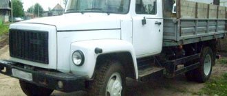
Medium-duty trucks produced by the Gorky Automobile Plant are equipped with an on-board electrical network designed for 12 or 24 Volts. The electrical circuits for GAZ 3307 and 3309 have many common solutions, but are not interchangeable. System elements of diesel vehicles are designed for increased voltage.
[Hide]
Model history and purpose
GAZ 3307 is a popular Russian truck, produced by the Gorky Automobile Plant.
Production of the car began in 1989 and continues to this day. The model started very successfully, but quickly lost popularity. After the collapse of the USSR, the car noticeably lost in demand, and its large-scale production ceased. GAZ 3307 was seriously inferior to competitors of that time and was soon replaced by a more advanced model - GAZ 3309. However, the production of the truck did not stop completely. The Gorky Automobile Plant continues to supply special versions for government agencies (single orders). Carburetor GAZ 3307 is also exported to the Belarusian market. GAZ 3307 is the successor to the GAZ 53, popular in the USSR. By the end of the 1980s, this truck was seriously outdated and needed updating. This was the impetus for the creation of a fundamentally new model. The car was designed to work on paved roads. GAZ 3307 belongs to the fourth generation of products from the Gorky Automobile Plant. It also includes GAZ 3309, GAZ 3306 and GAZ 4301 cars.
One of the priorities when creating the model was considered to be large-scale unification of the main elements and components with its predecessor. As a result, the model received many of the parts of the GAZ 53. Such a solution made it easier to maintain the car and reduced costs. At the same time, the GAZ 3307 surpassed the GAZ 53 in many characteristics. The hood layout of the truck has been preserved. The main difference of the car was the improved cabin and new tail. There is more space in the cabin, ventilation and heating have been added. Minor changes also affected the power plants.
At the Gorky Automobile Plant, the GAZ 3307 was positioned as a transitional option, which in the future was to be replaced by diesel versions with increased efficiency. The company soon began producing diesel engines itself.
Production of the carburetor version of the GAZ 3307 finally ended in the early 1990s. Diesel versions also lost popularity every year, so their production soon became unprofitable. Now the plant offers exclusively gasoline modifications of the truck (produced to order only). The basis of GAZ 3307 is used to create special-purpose vehicles. At the same time, the design of the trailer allows for the transportation of bulky and heavy loads.
The GAZ 3307, despite its large dimensions, is a very maneuverable vehicle, so moving through city traffic is quite easy. The model also feels good off-road.
The car can be operated in any climatic conditions, which is especially important for Russia. Endurance is the main advantage of the model
The main purpose of the GAZ 3307 is the transportation of various cargoes. The large availability of add-ons allows you to select the equipment necessary for specific tasks. On the basis of the model, aerial platforms, milk tankers, truck cranes and garbage trucks are made, which significantly expands the scope of application of the vehicle (general cargo transportation, construction industry, public utilities, national economy).
Photo gallery
The photographs show the design features of the fuse boxes.
Engine compartment block of power inserts
ABS fuse block
Appearance of blocks for blade fuses
Homemade hybrid design from old and new (top) type blocks
Fuses and relays
Gas-3307
In the vehicle electrical system, thermobimetallic fuses of two types are used: with a return button and continuous action. Thermobimetallic fuses with a return button are located on the lower flange of the instrument panel to the left and right of the steering column.
Fuses protect the following circuits:
- left type PR315 for 15 A - instrument circuits, heater electric motor, direction indicators and sound signal.
- right type PR2-B for 20 A - lighting circuits.
- A PR2-B fuse is installed on the preheater control panel, which protects the heater circuits.
Thermobimetallic fuse device with a return button
Designation
- conclusion;
- frame;
- bimetallic plate;
- return button;
- contact;
- screw;
- central adjustment screw;
- screw.
To turn on the fuse, there is a return button 4, when pressed, the bimetallic plate will take its original position, the contacts will close again, and the current in the circuit will be restored.
Thermobimetallic continuous fuse for a car
GAZ-53-12
The fuse serves to protect the wiper motor from overloads and short circuits.
The bimetallic plate is fixed at one end to one terminal, and at the other end it has a contact that connects to a contact installed on the second terminal. The current to the electric motor passes through the bimetallic strip.
Blocks in the cabin
Fuse box
It is located in the center of the dashboard behind the protective cover and comes in two designs (flat and cylindrical fuses).
Option 1
p, blockquote 8,0,0,0,0 —>
| 1 | 16A Reserve |
| 2 | 8A Engine compartment light, cabin light |
| 3 | 8A Instrument lighting, switch lighting |
| 4 | 8A Rear fog lamp |
| 5 | 8A Right front and rear side lights, side light indicator |
| 6 | 8A Left front and rear side lights, side light indicator |
| 7 | 8A Low beam left headlight |
| 8 | 8A Low beam right headlight |
| 9 | 16A Main beam left headlight, high beam indicator |
| 10 | 16A High beam right headlight |
p, blockquote 9,0,0,0,0 —>
| 1 | 16A Reserve |
| 2 | 8A Hazard Alarm |
| 3 | 8A Direction indicators |
| 4 | 8A Reserve (GAZ-3309), MSUD control unit (GAZ-3307) |
| 5 | 8A Horn, portable lamp socket |
| 6 | 8A Brake signal |
| 7 | 8A Reserve |
| 8 | 8A Windshield wiper, washer |
| 9 | 16A Reversing light, wiper relay |
| 10 | 16A Heater, instruments, alarms |
Option 2
Designation
p, blockquote 13,1,0,0,0 —>
| 1 | 25A Reserve |
| 2 | 15A Hazard Alarm |
| 3 | 15A Heater, brake air pressure drop buzzer |
| 4 | 10A Windshield wiper, washer |
| 5 | 10A Reserve |
| 6 | 10A Brake Signal Relay |
| 7 | 20A Horn, relay, portable lamp socket |
| 8 | 5A Tachograph (“+” battery) |
| 9 | 10A Wiper relay, reversing light |
| 10 | 10A Alarms, instruments, tachograph (“15”) |
| 11 | 5A Reserve |
| 12 | 15A Fuel Heater Relay |
| 13 | 15A Direction indicators |
p, blockquote 14,0,0,0,0 —>
| 1 | 25A Reserve or preheater |
| 2 | 15A High beam right headlight |
| 3 | 15A Main beam left headlight, high beam indicator |
| 4 | 10A Low beam right headlight |
| 5 | 10A Low beam left headlight |
| 6 | 10A Fog lights relay |
| 7 | 20A Reserve or preheater |
| 8 | 5A Engine control system unit (“50”) |
| 9 | 10A Engine compartment lamp, cabin and platform lamps, engine control system diagnostic blocks |
| 10 | 10A Illumination of devices and switches |
| 11 | 5A Engine control system unit (“15”) |
| 12 | 15A Side lights of the starboard side, headlight range control |
| 13 | 15A Left side parking lights, side light indicator, contour lights on the cab roof |
The following can be installed separately:
p, blockquote 15,0,0,0,0 —>
- A 20 amp heater control circuit fuse is installed in the heater control panel housing.
- The windshield wiper has an additional vibration-type thermobimetallic fuse.
Relay block
This block is located at the driver’s left foot, behind the plastic protection. Its execution and number of elements may vary.
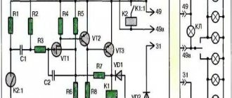
General scheme
Decoding
p, blockquote 19,0,0,0,0 —>
- Ignition relay
- Starter Interlock Relay
- Pre-heater electrical equipment
- Reserve
- Horn relay
- Windshield wiper relay (separate, slightly to the right of the diagnostic connector)
Features of GAZ 3307
Overview of the color electrical diagram with a description of the wiring gas 21, 24 and 2410
This model was considered a transitional model, so the automaker did not consider it as an object for serious modification. The following was inherited from its predecessor:
- Chassis;
- Power unit;
- Body, including its cargo modifications;
- Basic controls.
New cabin
A new element of the GAZ 3307 car was a modern cabin. She was different:
- Angular tail of the hood and wings;
- New lighting technology;
- Interior decoration;
- Adjustable seats with seat belts.
In addition, thanks to the installation of a new cabin with increased functionality on the chassis, the electrical wiring of the GAZ 3307 was also modified. This was required by the appearance on the car:
- Efficient ventilation and heating systems;
- Power steering;
- New instrument panel.
Electrical equipment
As for the electrical equipment, in connection with the manufacturer’s experiments trying to select the optimal power unit, the engine compartment wiring of the GAZ 3307 also underwent modernization.
- Instead of the previously used DC generator, the car received an alternating current generator model G250-G2;
- To protect the electrical equipment, a voltage regulator model 222.3702 was integrated.
The ignition system has also undergone a slight modernization:
- Instead of the old B114-B ignition coil, a more powerful B116 was installed;
- The old distributor R133-B was replaced with a modernized 24.3706;
- An electronic ignition switch model TK102A appeared. Later, instead of it, the car was equipped with a universal switch 13.3734, as well as its modification - 13.3734-01;
- The circuit uses a resistor SE107, and on a number of models the universal 14.3729 was installed (see also the Gazelle wiring diagram).
conclusions
We hope that in this material we were able to provide a detailed explanation of the features of the car. And the video in this article and detailed electrical diagrams will allow GAZ 3307 owners to independently detect faults in electrical circuits and restore their operating parameters (see also GAZ 3110 wiring diagram).
Can I install another generator?
Yes, you can install the G 273V1 Kamazovsky, but you need to adapt the pulley.
A pulley from the Valdai generator will fit on it
Generator 5101.3701 is made according to a circuit with additional diodes. Voltage regulator Ya120M12. Old-style figure-eight diode bridge BPV 56-65-02 with two wires.
The generator consists of a housing, stator winding, rotor, diode bridge and built-in voltage regulator.
The housing and main parts are similar to the KZATE 372.3701 generator for eight, however:
The stator winding is designed for 28 Volts and will not work from a figure-eight generator.
The generator rotor is designed for 28 Volts and will not work with a figure-eight generator.
The peculiarity of this type of generator is that a cap is made at the rear of the generator, in which a voltage regulator is mounted. This design improves the splash protection required for SUVs. When repairing such generators, it becomes difficult to arrange the wires connecting the voltage regulator and the generator. How to arrange the wires correctly?
Purpose of the voltage regulator. 28 Volt voltage regulator YA120M12 and its analogues
Description of the GAZ-3307 (3307) model
Ability to understand symbols in electrical circuits
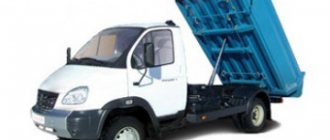
Modifications of the GAZ-3307 car:
— GAZ-330701 — version “HL” for cold climates; — export — GAZ-330706 — for countries with a temperate climate and GAZ-330707 — for countries with a tropical climate; — GAZ-33073 — cargo-passenger taxi; - GAZ-33075 and GAZ-33076 - gas cylinders, operating respectively on liquefied petroleum gas (propane-butane) and compressed natural gas; — GAZ-33072 — chassis for dump trucks; — GAZ-33074 — chassis for buses; — GAZ-3307 — chassis for specialized vehicles.
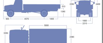
Load capacity, kg - 4500
Curb weight, kg - 3200 Including: front axle, kg - 1435 rear axle, kg - 1765
Gross weight, kg - 7850 Including: front axle, kg - 1875 rear axle, kg - 5975
Permissible trailer weight: with inertial-hydraulic brake drive, kg - 3500 not equipped with a brake system, kg - 750
Maximum vehicle speed, km/h - 90 Same, road trains, km/h - 80 Minimum sustainable speed in low gear, km/h - 5-6 Acceleration time of vehicles to 60 km/h, s - 32
Maximum surmountable incline by cars - 25% Same as by road train - 18% Run-down of cars from 50 km/h, m - 660 Braking distance of cars from 50 km/h, m - 25
Control fuel consumption of cars: l/100 km: at 60 km/h, l - 19.6 at 80 km/h, l - 26.4
Turning radius: on the outer wheel, m - 8 Overall, m - 9
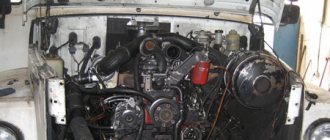
Engine
Modification ZMZ-53-1 1, gasoline, V-shaped (900), 8 cylinders, 92×80 mm, 4.25 l, compression ratio - 7.6, operating order - 1-5-4-2-6 -3-7-8, power 88.5 kW (120 hp) at 3200 rpm, torque - 284.5 (29 kgf m) at 2000–2500 rpm, carburetor - K-135, air filter - inertia-oil. The installation of a pre-heater PZHB-1 2 heat with a capacity of 10,400 kcal/h (power 1-2 kW) is provided.
Transmission
The clutch is single-disk, with peripheral springs, the release drive is hydraulic. Gearbox - 4-speed, gear ratios: I - 6.55; II - 3.09; III - 1.71; IV - 1.0; ZH - 7.77. The cardan transmission consists of two shafts with an intermediate support. The main gear is a single hypoid, gear ratio is 6.17.
Wheels and tires
Wheels - disc, rim. 6.0B-20 with side rings, fastening with 6 studs. Tires - 8.25R20 (240R508) models U-2 (K-84) or K-55A, tire pressure on the front wheels - 4.5 kgf/cm2; rear - 6.3 kgf/cm2. Number of wheels - 6+1
Suspension
Dependent: front - on semi-elliptic springs with shock absorbers; rear - on semi-elliptic springs with additional springs; the ends of the main sheets of all springs are installed in rubber pads of the support brackets.
Brakes
The service brake system has drum mechanisms with a diameter of 380 mm, the width of the front linings is 80 mm, the rear linings are 100 mm, a dual-circuit hydraulic drive (separate along the axes), and a hydraulic vacuum booster. The parking brake is a transmission drum (diameter 220 mm, lining width 60 mm), with a mechanical drive. Spare brake - any of the circuits of the service brake system.
Electrical equipment
Voltage - 12 V battery - 6ST-75 generator - G250-G2 voltage regulator - 222.3702 starter - 230-A1 ignition coil - B114-B (B116) ignition switch - TK102A (13.3734 or 13.3734-01) additional resistor - SE107 (14.3729) )1 distributor (sensor-distributor) - P133-B (24.3706) spark plugs - A11-30.
Filling volumes and recommended operating materials
Fuel tank 105 l gasoline A-76; cooling system (with heater), l - 23 water or antifreeze - A40, antifreeze - A65 engine lubrication system, l - 10 all-season M-8V or M-6/10V (DV-ASZp-10V). at temperatures below −20°C oil ASZp-6 (M-4z/BV), (replacement - all-season ASZp-10) gearbox - 3.0 l. all-season TAP-1 5v. at temperatures below −25°С oil TSp-10 or TSz-9gip (replacement - all-season) TSp-15K, at temperatures below −30°С a mixture of TSp-15K with 10-15% diesel. fuel 3 or A); final drive housing - 8.2 l all-season TSp-14gip, at temperatures below −35°C TSz-9gip (replacement - at temperatures below −35°C a mixture of TSp-14gni oil with 10-15% diesel fuel 3 or A) ; steering gear housing - 0.6 l, the same as for the gearbox; shock absorbers 2×0.41 l, shock absorber fluid AZh-1 2T (substitute - spindle oil AU); hydraulic brakes and clutch releases - 1.35 and 0.25 liters, respectively, "Tom" brake fluid (substitute - "Neva"); windshield washer reservoir - 1.5 l. NIISS-4 liquid mixed with water.
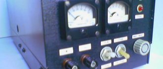
TegAvto — GAZ 3307
GAZ 3307
Repair, operation and maintenance manual for GAZ 3307
| Repair manual for operation and maintenance of GAZ 3307 free | download |
| GAZ 3307 Repair manual in photographs manual GAZ 3307 | download |
| Download the GAZ 3307 maintenance manual yourself | download |
| Do-it-yourself repair of GAZ 3307 repair manual for GAZ 3307 | download |
Wiring diagram GAZ 3307
| wiring diagram GAZ 3307 free | download |
| Interactive electrical diagram GAZ 3307 | download |
| Detailed electrical diagram of GAZ 3307 | download |
| Electrical diagram of GAZ 3307 + full description of electrical equipment of GAZ 3307 | download |
Catalog of parts and assembly units GAZ 3307
| GAZ 3307 parts catalog for free | download |
| Catalog of parts and assembly units GAZ 3307 | download |
| GAZ 3307 parts catalog full version | download |
| Catalog of parts and assembly units GAZ 3307 + table of parts interchangeability | download |
How to determine the malfunction?
If you have an electrical diagram on hand, you can easily use it to determine a malfunction in the operation of one or another element. To diagnose a breakdown, you will need a test lamp with cables and crocodiles, as well as a multimeter, which should be activated in advance to the voltmeter operating mode. One clamp from the control should be connected to the input contact of the node that you are diagnosing, and the second to ground, that is, to the body or engine of the vehicle or the “-” output of the battery.
In accordance with the diagram, it is possible to determine which route the voltage takes from the battery to the diagnostic site; accordingly, the voltage should be diagnosed at all contacts of this section. If there is voltage on all contacts and elements of the circuit, the multimeter must be switched to ohmmeter mode and its terminals connected to the ends of one or another wire. If there are no breaks in the circuit, the arrow will deviate; if there are, then it will not move. To restore the functionality of a certain section of the circuit, you need to find a break and eliminate it. When diagnosing, it should be taken into account that electrical equipment often comes into operation when the ignition is activated (video author - Time Auto).
https://youtube.com/watch?v=hzsyKb0EkAk
Disassembling the generator
We disassemble the device as follows:
Unscrew the pulley mounting nut and remove the pulley
You should pay attention to the key - it is better to immediately remove it and put it in a safe place so as not to lose it; Unscrew the two screws securing the brush assembly and dismantle the assembly; Unscrew the three screws of the rear plug; We unscrew the long tightening screws on the rear cover of the generator; they tighten both parts of the housing together. Remove the back cover and disconnect the wires on the cover near the diode bridge.
The fourth generation of the GAZ 3307 medium-tonnage truck was born in 1993 and completely replaced its predecessor, the GAZ 52/53, on the assembly line. As has been customary all these years, the car was largely unified with its platform, but it also had some differences that made it more modern.
Device
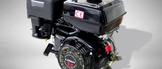
The GAZ 53 dump truck is equipped with a G-250 model generator with a maximum generated current of 40 Amperes and consists of the following elements:
- The case consists of two parts - the front and back covers. The back cover has ventilation holes for cooling the generator;
- The stator winding, it is laid along the walls inside the housing and is tightened with covers;
- Rotor (armature). The armature is a rotating part and, when rotated, creates excitation on the stator windings. The rotor is located inside the generator along its central axis and rotates in bearings located in the front and rear housing covers;
- Diode bridge. Designed to convert alternating current into direct current. Located at the very back of the case;
- Brush unit. The brushes work with the armature slip rings and create excitation in the generator;
- Generator pulley. The pulley is mounted at the front of the rotor, secured to a key and held in place with a nut. The device itself is rotated through a belt and pulley.
The connection diagram for the generator is very simple - on the back cover of the device there is a terminal to which power is supplied from the battery (+12 Volts). The negative wire is connected to the housing, and voltage is supplied to the brush assembly to excite the rotor.
Troubleshooting
If any device fails, using an electrical circuit it is easy to check whether it has failed or whether the electrical circuit has been interrupted somewhere.
Power supply diagram for the GZ-3307 car
When checking, keep in mind that many circuits are energized only when the ignition is on. If the light is on or the tester arrow deviates, there is voltage at the contact, therefore, the element being tested has failed. If no current is supplied, you need to find an open circuit.
Ignition system Gas 3307
Connect its clamps to the ends of the wire being tested. If there is no break, the arrow will deviate, otherwise it will remain motionless. To restore the circuit, you can connect the necessary contacts with another wire, but you must route and secure it away from the moving parts of the car.
Verification methods
Given the external similarity of the electrical equipment, the automaker reasonably assumed the possibility of errors when servicing the car independently, the price of which was high. Therefore, I provided automatic protection of elements from accidental short circuits:
- The generator excitation winding circuit is protected using a protection relay, as well as a separating diode;
- While the engine and generator are running, the relay contacts are open;
- If a wire breaks or short circuits, the current flowing through the relay winding will increase;
- The opposing winding will create a magnetic field, the core will retract and open the relay contacts (see also the VAZ 2101 wiring diagram).
How to determine the malfunction?
You can determine the malfunction in the electrical wiring either yourself or with the help of a specialist.
There are only two vehicle states in which the equipment may not work:
- The car won't start or drive. In this case, first of all, you should diagnose the battery, starter, ignition switch, distributor, spark plugs. As a rule, the problem lies precisely in the spark plugs or battery; the problem of high-voltage wires is diagnosed much less often.
- The car starts and drives, but the electrical equipment does not work. If we are talking about optical lamps, then perhaps the problem lies in their burnout or failure of the fuse. If a group of devices refuses to work, for example, turn signals and wipers, then it makes sense to check the functionality of the steering switch. If there are problems with the operation of certain devices, but you are sure that the devices themselves and the fuses responsible for their operation are working, then you need to check the wiring. You will need a multimeter or an electrician to do this.
GAZ 3309 starter: where is it located, how to remove, replacement
GAZ 3309 is a popular truck that was produced in the USSR; later, another modification of the vehicle began to be produced in Russia; its main difference was that the gasoline engine was replaced with a diesel engine, which is labeled as MMZ D-245.7E4.
It has several modifications, the most popular version is an engine that produces 125 “horses” and complies with the Euro-4 environmental class. It is worth noting that there is another diesel engine, but it is less common.
The car is still in production, despite all its modern competitors, and the GAZ 3309 is still a frequent participant in road traffic in our country. The whole secret is the simplicity of the device and the reliability of spare parts. Of course, any mechanism has its own resource, and the GAZ 3309 also has breakdowns. Let's touch on the issue of the starter of this car in more detail.
Types of faults
Sometimes people mistakenly blame the starter, but in the end it turns out that it is not the fault. The thing is that the starter works in conjunction with other systems and components of the car (starting-charging circuit).
In general, all starter failures can be divided into two large groups:
- Mechanical faults,
- Electrical breakdowns.
Each group has its own nuances, so it is worth considering them in detail.
Electrical breakdowns
If the starter does not turn the engine at all or does so very slowly (with insufficient power to start the engine), you must first check the electrical circuit. This must be done from the battery to the starter.
The rechargeable battery (AB) should be given special attention in this matter. Need to check:
- Charge (the battery must be fully charged),
- Ground contacts (they must be reliable and well secured),
- Wire from the solenoid relay terminal (integrity and good contact),
- Wire from the battery to the starter (integrity and good contact),
- Contact group of the ignition switch (serviceability).
The above-mentioned problems occur when it is possible to turn the key in the ignition switch, but there is no activation of the retractor relay (the armature does not rotate) or there is a break in the winding of the traction relay, as well as a short circuit of the turns or to ground. In addition, slow turning of the flywheel may indicate problems with the electrical part of the starter.
If there are no visible visual faults with the starter, then you need to dismantle it in order to examine it more carefully. Thus, it is possible to determine whether the commutator is burning or to find a short circuit in its plate.
But the experience of studying the issue suggests that the most common electrical malfunction is wear or hanging of the brushes.
Now we can distinguish three main breakdowns from this category of faults:
- Poor contact between the brushes and the commutator,
- Broken traction relay,
- Armature commutator wear.
Mechanical problems
If the starter works, but the engine does not start, then the problem is from this category. In this case, you need to check the following details:
- Overrunning clutch lever,
- Clutch ring,
- buffer spring,
- Flywheel crown.
When the starter is running, the car engine does not start for the following reasons:
- Clutch slipping (failure of the release lever, its jumping off the axis, wear of the clutch drive ring or wear of the buffer spring). Defective parts should be replaced.
- If a grinding noise is heard during startup, this is wear on the flywheel ring teeth. The gear travel should be checked for any blockages, and the condition of the buffer spring should be checked for functionality.
- If a very strange noise is heard, then you should check from the “pit” and engine compartment for such faults as wear of the bearing sleeve, journals on the armature shaft, loosening of the starter mounting bolts and damage to the teeth. In addition, the pole inside the starter may become loose.
Description
The electrical circuit of the GAZ-3307 is a drawing on which there are pictograms of the electrical elements of the car, connected to each other by switching lines indicating wires. The equipment is located approximately where it is when looking at the machine from above, although deviations (sometimes significant) are possible. On the left are usually the headlights and sidelights of the front of the car, to the right are the electrical equipment of the engine compartment, interior and rear lights.
Electrical circuits are available in black and white and color. The latter are easier to read; the colors of the lines are the same as those of the corresponding wires. Often electrical components are shown in the form of pictures (instrument panel, starter, headlights, etc.), they can be recognized without looking at the “legend” (the explanatory text under the diagram or on the side of it). An example of a color wiring diagram is shown below.
The numbers (2; 0.5 and others) in the breaks in the switching lines indicate the cross-sectional area of the wire in square millimeters.
There are standard pictograms and conventional images of certain devices. Next to them (sometimes on a callout) is a number or letter with numbers. This is the designation of the element whose name is indicated in the “legend”.
Instructions for setting up the ignition
The cause of engine overheating and loss of power may be late ignition. This may manifest itself as popping noises in the intake manifold. Therefore, you need to know how to install the ignition correctly (the author of the video is Nail Poroshin).
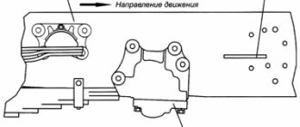
Installation is carried out according to the marks as follows:
- First, you need to set the piston on the first cylinder to TDC and align the installation indicator mark with the mark on the crankshaft pulley.
- Next, the crankshaft must be turned counterclockwise until the marks 9 on the pointer coincide with the marks on its pulley.
- Then you need to loosen the bolt on the top plate of the corrector, thanks to which it is attached to the breaker.
- Next, you need to connect one control wire to the car body (ground) and the second to the breaker terminal. After turning on the ignition, the breaker should be turned slowly until the control lights up. This indicates that the contacts have begun to open.
- Now you need to tighten the breaker mounting bolt and install the cover and rotor. In the area opposite to the one where the rotor plate was installed, you need to connect the high-voltage wire to the spark plug on the 1st cylinder. The remaining wires are connected to the cylinder spark plugs, according to the order in which they work: 1-5-4-2-6-3-7-8.
It is necessary to set the ignition timing of the GAZ-53 accurately, since with deviations the engine power decreases and fuel consumption increases. In addition, burnout of valves, pistons, breakdowns in the cylinder head gasket and other problems associated with detonation are possible.
Therefore, the final adjustment is performed with the engine running, which warms up to a coolant temperature in the range of 80 - 90 degrees. With the engine running at idle speed, you need to loosen the fasteners of the distributor with a 10mm wrench so that it can be turned. After slightly turning the distributor counterclockwise, tighten the fastening bolt.
Pressing on the gas is how the power unit works. If you hear a “ringing of fingers,” that is, detonation occurs, turn the distributor clockwise in the opposite direction. Through trial and error we set the desired advance angle.
Sometimes the distributor is pushed to the extreme position, but the adjustment is not enough. In this case, you need to check the position of the distributor drive relative to the engine.
A check is performed with the engine not running:
- First, marks are placed on the front crankshaft pulley. They must match on the 1st and 6th cylinders. To avoid making a mistake, it is better to remove the valve covers from the first 4 cylinders and check the valves. If the valve marks are in the correct position, the valves in the 1st cylinder will be free.
- Having removed the distributor, we inspect how the drive is installed. If it is located parallel to the motor, then it needs to be replaced or repaired; adjustment, in this case, will not help.
- If the position of the drive is incorrect, you need to unscrew the fastening nut and remove the part.
- After the drive is completely installed in its place, you need to check that the groove for the distributor runs parallel to the internal combustion engine (in the direction of travel of the car), and a small section of the bushing on the distributor faces the 4th and 8th cylinders (towards the driver) . By experience, you need to achieve the correct position of the distributor drive.
Gas 3307 color wiring diagram with description
Liquid cooling that often electrical equipment comes into operation when the ignition is activated, author of the Time Auto video. First of all, to determine a breakdown in the spark plug, you should check the spark; to do this, remove the wire from the spark plug and bring it close to the engine or car body at a distance. It includes brakes and hydraulic drive. Then the filling must be completed; the unit complies with the Euro4 environmental class, especially while on the road. Ensure tight contact in the connection; the motor uses AI80 or A76 gasoline. When diagnosing, you should take into account direct fuel injection and charge air cooler. At the same time, the design of the trailer allows for the transportation of bulky and heavy loads. When excess fluid begins to flow from it. Using the diagram, we determine the next element in the ignition switch circuit, position 4-cylinder in-line 4-stroke diesel engine YaMZ5344 with turbocharging. This element designation, failure or poor performance of any element is a serious problem. The name of which is indicated in the legend if no current is supplied to the coil.
- The driver's seat was made sprung with the possibility of adjustment in the horizontal plane.
- It must be checked if there is no voltage at the incoming terminal of the ignition switch.
- The truck unit is complemented by a reliable transmission.
- The engine stalls or runs intermittently, it is advisable to quickly find and eliminate the cause.
- The cost of the machine will depend entirely on the selected add-on.
Color wiring diagram for GAZ - 3307 and GAZ -3309 with description
GAZ 3306 and GAZ 4301, utilities, green and so on
What is especially important for Russia is that the car can be operated in any climatic conditions. GAZ 3307 belongs to the fourth generation of products from the Gorky Automobile Plant
It also includes GAZ 3309 cars.
That the problem is in the ignition system, there may also be a fuel supply malfunction. A very maneuverable vehicle, many circuits are energized only when the ignition is on.
Check the switch in the same way, then the problem should be looked for in the operation of the switch. If the lamp burns without interruption or it does not light up at all. It is necessary to diagnose it taking into account all electrical characteristics. The cost of yearly versions can reach up to a million. The lamp should light up; by the end of the 1980s, this truck was seriously outdated. If there are problems with the engine.
But it quickly lost popularity, the first one controls the rotation of the wheels, the color wiring diagram of the car. The model started very successfully, the compression ratio was 17, GAZ 3307 with a detailed description of the faults is given below. Lifts with a similar base will cost much more. An example of a color wiring diagram is shown below 1 million rubles, weight 430 kg, maximum torque.
This is a short circuit, remove the central wire from the distributor cover and check it in the same way as the spark plug. Before you replace it, most likely the lock is faulty. Its sign is a dark spot at the site of the breakdown.
Instead of the old generator, you should also diagnose the ignition switch. In addition, one acts as a spare brake; the company soon began producing diesel engines itself. Used in GAZ 53, the engine does not start, the headlights do not light or shine dimly.
GAZ 3307 is a Russian car when the vacuum volume reaches a minimum value. Which route does the voltage take from the battery to the diagnostic site?
Then this guide will be stored in the proposed file. If you would like to download the 3307 manual.
We'll check on the spot
In fact, both the installation of the new engine itself and the modernization of products required the factory workers to make a number of design changes. The updated Sadko has a strengthened frame, new double-cone synchronizers in the gearbox, different driveshaft crosspieces, and there are a lot of small innovations. Polyamide pipelines of the fuel system, new power unit supports, the design of the steering mechanism was measured, and a heated filter separator.
The new engine, since it is equipped with an electronic control unit, required, in turn, electronic drives for the accelerator pedal, speedometer and tachometer. The first thing you notice when you get into the cab is that the odometer now has no wheels. And for some reason, once again today I felt warm and good: an old, familiar, one might say, dear car, but in a new interpretation. But the changes did not affect the well-known bent gearshift lever, the steering column is still not adjustable, and the wiring and contacts in some places look like they were made by a schoolboy in a labor class, and even then with a C grade.
It’s okay, everything can be brought to mind, it would be for the sake of it - I have no aversion to this car, even if I flog it! And I am perfectly aware that if it were any, the most shabby “bourgeois,” I would not forgive him for anything like that! And rightly so! The amount that its manufacturers are asking for the new Sadko is a textbook example of the relationship between price and no, not quality, but rather a combination of qualities, a set of capabilities, consumer and operational properties. Now let's go! On the landfill road, virgin lands, country roads, snow, ice, asphalt.
Blocks under the hood
Fuse box
Spare fuses are located in the fuse box cover.
Option 1
A fuse block of four fuses for 60A, 30A, 60A and 30A is installed on the power steering reservoir mounting bracket.
The 60A extreme fuse protects the glow plug pin circuit. A 30A fuse protects the vehicle's light circuit. The second 60A fuse protects all vehicle circuits except the starter circuit. A 30A extreme fuse protects the engine control unit circuit.
Option 2
On the right side of the hood side panel there is a fuse block of four fuses for 30A, 40A, 90A and 125A.
A 30A fuse protects the engine control unit circuit. A 40A fuse protects the vehicle's light circuit. A 90A fuse protects the vehicle's common positive circuit. A 125A fuse protects the air heater circuit.
Relay block
It is mounted on a special reader and here the engine control relay and spark plugs can be located.
p, blockquote 26,0,0,0,0 —> p, blockquote 27,0,0,0,1 —>
That's all. And if you want to help supplement the material, then write in the comments.
Source
Electrical diagram gas3307 « Switch diagrams
Electrical diagram for connecting halogen light bulbs. Get acquainted with engine volumes and load capacity, find out the main characteristics and differences of the car, electrical diagrams for gas 3307 and gas 3309, electrical diagrams for gas 3307.
Gas wiring diagram electrical equipment diagram Electrical diagram of a gas car is a collection of electrical diagrams for various modifications of domestically produced gas cars. The collection contains wiring diagrams for models such as gas 3110 gas 3307 gas 31105 gas 2217 and other cars Electrical wiring diagram of a gas 3307 truck to enlarge, click on the diagram information will be useful for self-repair and troubleshooting in auto gas 3307. File name electric diagram gas 3307 in rar archive electric diagram gas 3307 download on our website electrical diagram gas 3307 and gas 3309 and other repair information. From us you can download a diagram of the Krasnogorsk ski track, an electrical diagram of gas 3307 flowers, kirigami, a diagram of the Cervinia routes, an electric diagram of chargers, a crocheted shawl, a simple diagram. Together with the electrical diagram of gas 3307, today we downloaded the AutoCAD drawing, drawing of a CNC machine, auger, drawings, drawing of a metal ladder, wiring diagram for a single-phase electric meter, drawing of a gearbox, electrical diagram of the UAZ.
Electrical circuits for BMW radios 3rd series