What do we know about tractors? What is this working equipment that is rarely seen by city dwellers; they mainly work in the fields? We know practically nothing about their capabilities and purpose.
We propose to fill this gap and get acquainted with the legendary equipment that is still working and fulfilling the tasks assigned to it.
The K-700 tractor is a cross-country vehicle. General purpose category. Belongs to the fifth traction class.
Purpose: work in the construction field, road work. Used in the transport sector. A large amount of work was performed by tractors in agriculture.
Sowing crops, plowing the land, cultivating, disking. Participates in reclamation work. This is not a complete list of the capabilities of powerful and reliable technology.
History of the K 700 tractor
1961 is the time of the first steps of a new generation of Soviet wheeled vehicles.
Later he would be called the “steppe hero.” It was K 700 that developed the Kazakh lands. But the geography of application did not end there. The hero tractor took part in the development of northern latitudes. We will not dwell in detail on his “biography”. Just two words.
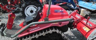
It has come a long way, the K 700 photo tractor that you see has been modernized several times, rolled off the St. Petersburg factory assembly line in 2002.
Watch the video about the assembly of parts at the manufacturer's plant of the K 700 tractor.
Spare parts for mini tractors, features of their selection and purchase, components for Japanese mini tractors.
You can find out more about the Bulat 244 minitractor here.
Tractor electrical equipment - K-701:
1 1 2 3 4 5 6 7 8 8 8 8 8 9 9 10 11 12 13 14 15 16 17 18 19 20 21 22 23 24 24 24 25 26 26 26 26 27 28 29 29 30 31 31 31 31 32 33 33 33 34 35 36 37 38 39 40 41 42 42 42 42 42 43 44 45 46 47 48 49 50 50 51 52 53 54 55 56 57 58 59 60 61 62 62 63 64 64 64 65 66 67 68 69 70
List of components from Tractor electrical equipment for K-701
Parts diagrams are for reference purposes only! We do not sell all spare parts for tractor electrical equipment for the K-701 presented in this list. If there is a “Show prices” link in the right column, these spare parts from “Tractor Electrical Equipment” are on sale. Availability in warehouses for details and prices, see the product card. If there is no “Show cost” link in the right column, we do not sell such parts and do not accept orders for them.
| № | Part code | Name | Part Information | Show all prices |
Specifications
Table 1 shows the main characteristics of the technology.
Table 1 — Tractor K 700 technical specifications
| Power unit | YaMZ-238NM | |
| Power | ||
| l/s | 230 | |
| kW | 169 | |
| Fuel tank | l | 450 |
| Speed data | ||
| Moving forward with speed | km/hour | 33,8 |
| Reversing | km/hour | 24,3 |
| Dimensions | ||
| Length | mm | 7400 |
| Width | mm | 2880 |
| Height | mm | 3950 |
| Tractor weight | T | 11,9 |
| Ground clearance | mm | 440 |
| Track (width) | mm | 191 |
Engine
Under the hood of the K 700 Kirovets there was initially a YaMZ-238NM power unit with eight cylinders. It was mounted with rubber shock absorbers in the front part on a semi-frame with three supports. The fuel system included two filters:
- Rough cleaning.
- Fine cleaning.
Minitractor Bulat 264E - device features and cost.
The HTZ-2511 tractor and its technical characteristics are here.
Dongfeng DF 244: its characteristics and components are here.
Electrical diagram
Figure - Electrical connection diagram of the K 700A tractor.
The electrical circuit of the K 700 tractor included: ammeter, tachometer, pressure gauge. Rechargeable batteries, DC. A device showing water temperature. Oil temperature indicator.
Electrical equipment of tractors K-701, K-700A (Kirovets)
The tractor electrical equipment system is single-wire, the negative terminals of both power sources and consumers are connected to the body (“ground”) of the tractor. The voltage in the network is mixed: 12 and 24 V. 24-volt circuits have a starter and an electric motor for the oil pumping unit on the K-701 tractor and only a starter on the K-700A tractor, since there is no oil pumping unit on the K-700A tractor. The electrical equipment diagrams of the K-701 and K-700A tractors are shown in Fig. 61 and 62. The sources of electricity are batteries and an alternating current generator with a silicon rectifier built into the lid, working in conjunction with a relay regulator. The main consumers of electricity are the starter; electric motors driving the oil pumping unit, heater, dust separator fan, heating system blower, driver fan; fuel heating coil; glow plug; lighting and alarm system; control and measuring instruments.
A description of the design of the generator and starter, as well as instructions for their operation and maintenance, are given in the diesel manufacturer's instructions, which are supplied with the tractors.
Relay regulator for tractors K-701, K-700A (Kirovets)
The relay regulator is designed to automatically maintain the voltage in the tractor's on-board network within 13.6...14.2 V in summer and 14...15.2 V in winter, which is necessary to ensure normal operation of consumers and charging mode of batteries.
The regulator does not require special maintenance. When carrying out preventive maintenance, it is necessary to carry out an external inspection of the regulator, clean it from dirt, check the reliability of the regulator fastening and the electrical contact of the supply wires.
To change the regulated voltage during seasonal adjustment, the regulator has a “Winter-Summer” seasonal adjustment switch located on the rear wall of the housing.
During operation it is prohibited:
a) start the diesel engine with the positive wire between the generator and the regulator disconnected, and close the terminals B and W for a long time, more than 2 s, as this will lead to increased voltage in the on-board network, which is dangerous for consumers;
b) close terminal B to the body;
c) connect the supply wires incorrectly;
d) open the regulator during the warranty period.
Batteries for tractors K-701, K-700A (Kirovets)
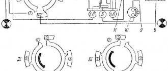
The tractor is equipped with two 12-volt batteries, one battery on the right and left sides of the tractor. Each battery consists of six two-volt cells connected in series. When the tractor is operating, the batteries are connected in parallel, and when starting, the batteries are connected in series (Fig. 63). A description of the device and instructions for its operation and maintenance are given in the attached
Rice. 63. Battery connection diagram a) - parallel connection; b) - serial connection
Battery switch for tractors K-701, K-700A (Kirovets)
The switch is designed to switch batteries from a parallel connection (12 V) to a serial connection (24 V) to power the starter and the electric motor that drives the oil pump. The switch consists of a contact box 2 (Fig. 64) with output terminals 1 for connecting wires, an electromagnet 6 with a movable core 7, contacts 9, movable contact disks (main 4 and additional 5), main contacts 3 and additional contacts 8.
At the end of the switch there are terminals: +B1, +B2, -B2, PC, M. The following wires are connected to these terminals:
- to terminal +B1 - wires from the positive terminal of the left battery and from the minus terminal of the current indicator;
— to terminal +B2 — a wire from the starter terminal, which in turn is connected to the “plus” terminal of the right battery;
- to terminal - B2 - wire from the negative terminal of the right battery;
— to the PC terminal — wire to the electric motor winding of the oil pumping unit, wire to the starter activation relay terminal;
- to terminal M - wire from the ground switch terminal.
On the side surface of the switch there are two electromagnet winding terminals to which wires are connected: from the switch on button and from the tractor ground.
Rice. 64. Battery switch 1 - output terminal; 2 — contact box; 3 - main contact; 4 — disk of main contacts; 5 - additional contact disk; 6 - electromagnet; 7 - movable core; 8 - additional contact; 9 — contacts; 10 - PC terminal; 11 - terminal: positive +B2 and negative -M
contents .. 41 42 ..
Tractor gearbox K-700 and K-701: diagram and repair
In this article we will look at the design and principle of operation of the gearbox of the Kirovets K-700 and K-701 tractors, because their structure is completely identical. We will also give the main points in the adjustment, maintenance and repair of this mechanism.
Section of the hydraulic clutch of the K-701 and K-700 tractor gearbox
1 and 4 - drive gears of 2nd and 1st gears; 2 - driven drum; 3 - driving drum; 5 and 6 - nut and oil line tension spring; 7 - oil line; 8 - clutch release spring; 9 and 10 - driving and driven disks of the clutch; 11— sealing rings; 12—pressure disk; 13 — middle disk; 14 - drive shaft; A - cavity of the hydraulic clutch; B - throttle hole; B - cavity of the inner drum; G—holes in the drive drum; D - holes in the driven drum; E - channel for supplying oil to the oil line.
The primary shaft 39 is hollow and rotates on three bearings: ball and two roller. Four hydraulic clutches are mounted on the shaft. Their driving drums 3 (see diagram) are fixedly mounted on the shaft splines, and the driven drums 2 are attached to gears that rotate freely on two roller (outer clutches) or ball (middle clutches) bearings.
Device
Maneuverability and traction of all wheels with the soil are ensured by two semi-frames that move relative to each other. The main part of the working units is mounted on the front semi-frame, which has increased strength. The tractor wheels (4 in total) have equal dimensions, operate at low pressure and are equipped with an all-terrain tread.
Engine
The model is equipped with a 12-cylinder high-power diesel engine (300 hp), which is mounted on one front and two rear supports. The engine is installed in the front semi-frame of the tractor, the vibrations of which are damped by effective rubber shock absorbers.
The cooling fan has automatic speed control to help maintain optimal temperature conditions.
To ensure cold starting, a comprehensive engine and fuel heating system is used. Driving off can be done only after heating the coolant to a temperature of 40-50 °C.
The diesel air filtration system is two-stage. At the first stage, processing takes place in a cyclone, after which the air, purified from the coarsest impurities, passes through a high-porosity cardboard filter. A clogging indicator is used to visually monitor the condition of the air system.
Tractor transmission
The transmission system includes a semi-rigid clutch, gearbox, axles and cardan drive. The pump drive gearbox is connected to the transmission clutch. Both axles (front and rear) are driven, and the rear axle can be disengaged. This reduces fuel consumption without the need for high power output.
The gearbox has 16 forward and 8 reverse speeds. The gearbox is installed on the front semi-frame of the tractor and secured through shock absorbers with four brackets.
Hydraulics
Work with attachments is carried out using a separate hydraulic system. In total, two NSh-100 pumps are installed in the tractor, one of which works to meet the needs of the tractor, and the second goes to the attachments.
Tractor diagram K-701
Adjustable distributors, which are equipped with models of recent years of production, allow the operation of most imported agricultural equipment. Hydraulic operation is integrated into the gearbox and steering system.
Electrical equipment
Engine starting is ensured by an 8.1 kW electric starter. It is powered by two batteries (12 V), which are switched from parallel to serial connection to run.
The tractor generator is three-phase and has a silicon rectifier (produces direct current).
The functions of the electrical system are used to solve problems:
- ensuring engine preheating;
- starting a diesel engine;
- power supply system;
- functioning of heating and ventilation;
- power supply for lighting devices (inside and outside the cabin).
Road lighting and traffic signaling are based on the operation of two headlights with cornering lights, as well as two markers and cornering lights at the rear of the cab.
Diagram of the K-701 tractor pump drive shaft
Steering
Ensuring tractor controllability is achieved by combining hydraulic and mechanical systems. Communication with the driver is made through the steering column, in contrast to tracked lever units.
The oil temperature in the system is forcibly maintained by passing through the radiator. Separate supply of the steering unit and attachments with hydraulic fluid is not provided, so they are equipped with a common tank.
Attachments
Attachments are secured using a lever-joint mechanism with a three-point suspension system. The range of external tractor equipment is wide, being intended to support the agricultural sector (mainly).
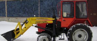
The most popular mounted systems include a loader, plow, ripper, cultivator and combined units. The total range of equipment for the K-701 tractor exceeds three dozen items.
| Loader Specifications | |
| Load capacity | 3500 kg |
| Bucket capacity | 2000 l |
| Unloading height | 3 m (maximum) |
| Weight | 3700 kg |
| Technical characteristics of the cultivator | |
| Performance | 16 ha/h |
| Working width | 18 m |
| Speed during operation | 12 km/h (maximum) |
| Processing depth | 16-120 mm |
| Ground clearance | 0.3 m |
| Full mass | 6.2 t. |
The video shows the K-701 tractor with a cultivator:
Operating principle of gearbox k 700 – Special equipment
In this article we will look at the design and principle of operation of the gearbox of the Kirovets K-700 and K-701 tractors, because their structure is completely identical. We will also give the main points in the adjustment, maintenance and repair of this mechanism.
Gearbox for K-700 and K-701
The transmission of the K-701 tractor is four-range, with constant mesh gears, with mechanical range switching when the tractor is stopped and hydraulic gear shifting within each range without stopping the tractor.
The K-701 gearbox provides 16 forward speeds and 8 reverse speeds.
The gearbox housing rests through shock absorbers on four brackets of the tractor's front half frame and consists of an upper and lower halves - a spacer and a pan. The pedal and control levers are mounted on the crankcase.
Transmission diagram of the K-701 and K-700 tractors
A schematic section of the gearbox (along the shafts) is shown in the diagram below. The gearbox has four main shafts.
The primary (drive) shaft 39 is driven into rotation by the flange 40 of the front cardan drive. Below are the intermediate 36 and cargo 31 shafts.
In the lower tide there is a transfer case 24 with a flange 25 for the drive of the front drive axle and 18 for the drive of the rear drive axle.
1- oil pump drive shaft; 2 — pump drive gear; 3 — pump drive switching clutch; 4, 7, 8 and 10 - gears with driven drums of IV, III, II and I gears; 5 and 6 - driving and driven gears of the pump drive; 9 — bevel gears of the pump drive; 11 — flange of the cardan drive of the PTO coupling; 12, 13, 34 and 37 - driven gears of 1st, 2nd, 3rd and 4th gears; 14 and 35 - intermediate shaft gears for high and low operating and transport speeds; 15 and 16 - gears of the cargo shaft and reduced operating and transport speeds; 17— rear axle drive flange; 18— rear axle drive shaft; 19 — gear movable clutch for disabling the rear axle; 20 and 23 - transfer gears for reduced and increased operating and transport speeds; 21— gear movable clutch for switching on low and high speeds; 22 — transfer gear; 24 - dispensing; 25 — front axle drive flange; 26 and 28 — cargo shaft gears; 27 — gear movable clutch for changing speed modes; 29 — gear clutch for enabling rear speed modes; 30 — cargo reverse gear; 31 - cargo; 32 — reverse intermediate gear; 33 — gear axis; 36 - intermediate; 38 — reverse gear of the intermediate shaft; 39 — primary (leading); 40 — gearbox driveshaft flange; 41 — helical gear of the tachometer speedometer drive.
On the cylindrical surface of the drive (inner) drum there are splines along which five steel toothed friction disks 9 can move.
They are located between six toothed disks 10 sliding along the splines of the outer (driven) drum.
A pressure disk 12 is installed on the hub of the drive drum, which compresses a package of friction squeaks under oil pressure.
Oil enters the cavities A of the outer hydraulic clutches through oil lines 7, and into the same cavities of the middle couplings it is supplied through channels from the middle shaft support. Sealing pins 11 prevent oil from flowing out of cavity A, but some of it passes through the throttle holes B into cavity B of the inner drum.
From here, through holes D in the drum, the oil is thrown onto the friction discs, and then through holes D in the outer drum it is drained into the gearbox housing. When the clutch is turned off, springs 8 press disk 12 away from the pack of friction disks, displacing oil from cavity A back through the same channels.
Synchronizer brakes are installed on the driven drums of 1st and 4th gears.