This catalog covers car spare parts. The alternator can be controlled while the engine is idling by connecting alternately to the terminals of each two phases of the generator! Control and adjustment work on the engine [] Basic. According to the fuse table, we find that the low beam filament of this headlight is protected by fuse Pr. When choosing circuit protection, the inappropriateness of introducing fuses in the ignition, power supply and engine starting circuits was taken into account, since this reduces the reliability of the systems. Learning to read a car's electrical diagram. Part 1. Auto electrics.
To control the rectifier, connect a voltmeter or test lamp to its positive and negative terminals and disconnect the wire from terminal B of the relay regulator. To determine whether a wire is shorted to the car body, it is necessary to disconnect the ends of the wire being tested from the terminals and connect one end in series with a lamp or voltmeter to the positive terminal of the battery. Having found the brake light switch on the general electrical diagram, we see that two wires go to it: white and red purple. Broken wires must be replaced with intact ones.
General Truck Design Possible Wiring Problems A disadvantage of the truck's proximity system in the old days was the lack of electronic components and their reliability for use in harsh weather conditions.
A complete diagram of the vehicle's electrical equipment is given in each instruction manual for the vehicle.
Also shown are electrical diagrams of cars of various configurations and If the ammeter needle is at zero or shows charging, then the generator is working; 2 start the engine; turn on all network lamps; disconnect wires B, W and Z of the relay regulator from the terminals; Connect the ends of these wires together.
We connect RS 502 to the starter
Features of electrical equipment
The car used the following, traditional for the domestic automobile industry:
- Single-wire circuit, where the role of the second wire is played by the metal body of the car;
- All electrical equipment is designed for 12 V;
- The starter operates on 24 V (a second battery is installed for this purpose);
- The main circuits are protected by fuses;
- As a basis, according to the unification of parts, the electrical wiring of ZIL 4331, the successor to ZIL 130, was used.
The factory instructions indicated the catalog numbers of the parts used
Features of cabin wiring
Having inherited the high cabin from the “big” brothers, the designers also used the interior wiring diagram of the ZIL Bychok without any special changes.
It allowed:
- reduce assembly costs;
- and for consumers - an acceptable price was offered for a “delivery” city truck.
Photo of the cabin, unified with older models of previous years
The old cabin also inherited some of the “features” of its predecessor.
In this connection, the owners operating this car were forced to correct the shortcomings with their own hands, namely:
- The power of the electric washer pump was not enough, since water was first supplied to the right blade, then to the middle one, and only then to the driver's side wiper blade;
- additional insertion of two nozzles into the hood solved the problem.
Dashboard
The main difficulties in operation arise in the work:
- ignition switch;
- main switch (located behind the battery box).
The instrument panel used upgraded wiring ZIL 4331
Technical parameters of the part
Devices of this type are characterized by the following technical parameters:
- Dimensions are determined by the following dimensions: 32 by 18 and by 15. Such indicators guarantee the location of the device without interference or inconvenience of access to it or adjacent parts.
- The starter with a total weight of 9 kilograms 200 grams can be moved, removed and mounted back to the machine components without problems and great effort.
- The voltage required for the mechanism to operate is 12 V.
- For correct and trouble-free operation of a starter of this model, it is important to provide the car with a battery with a minimum capacity of 90 Ah.
- The holding winding provides 11 amperes.
- The kit includes a 3mm gear.
- The starter drive gear has 9 identical teeth for reliable and durable engagement with other related parts.
The advantages and distinctive features of the ZIL 130 starter will be the following main points: a reliable and durable metal case ensures the durability of the device and its compact dimensions. A proven gear mechanism is a guarantee of a high performance coefficient, which is an important condition for good, comfortable operation of the car.
The device retains its functionality and performs its functions perfectly even when the starting current in the car battery drops.
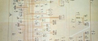
Colored electrical diagram of the electrical equipment of ZIL 131 and 130 with a description of the wires
Electrical diagram of KamAZ trucks
The ZIL 131 multi-purpose truck has been used in the army for many years, and after modernization it continues to be used in various sectors of the national economy. The article discusses the electrical equipment of the truck, the main faults, and provides a color diagram of the ZIL 131 electrical equipment.
Features of electrical equipment
From 1966 to 1086, ZIL 131 was produced unchanged (the author of the video is Ivan Zenkevich PRO cars).
Then three modifications of it came out:
- with carburetor engine;
- with diesel engine;
- with unshielded wiring for civil needs.
The truck has high performance qualities, but besides these, its design has features that domestic manufacturers have not used on other vehicles:
- a gasoline engine with 8 V-shaped cylinders and 16 valves is installed;
- the traditional ignition system has been replaced with a contactless one equipped with an electronic switch;
- the use of shielded sealed electrical wiring made it possible to operate the ZIL 131 in any weather conditions.
How to determine the malfunction?
Problems associated with electrical equipment can be identified by the following symptoms:
- Generator: does not provide charging current, bearing noise during operation, high charging current.
- Starter: does not work; does not rotate the engine crankshaft; the rotor rotates, but does not rotate the crankshaft; when turned on, frequent clicks of the solenoid relay are heard; After starting the engine, the starter does not turn off.
- Battery: discharges quickly; The electrolyte level in the battery decreases quickly; Electrolyte spills from the ventilation holes; During charging there is a slight increase in the density of the electrolyte.
- Ignition system: the contacts in the connections of the ignition system components are broken, the power unit does not start.
Possible wiring problems
The downside to the truck's proximity system in the old days was the lack of electronic parts and their reliability to handle harsh weather conditions.
Wiring problems may occur due to:
- circuit break;
- damage to current-carrying elements: cores, contacts, wires;
- poor contact at connection points;
- oxidation of terminals and contacts;
- insulation damage;
- lack of food.
An open circuit can be determined using a voltmeter or test light.
Broken wires must be replaced with intact ones. If it is not possible to make a replacement, you can temporarily connect the broken ends of the wire by wrapping them with insulating tape.
You should ensure that the contacts are clean, otherwise the current will not be able to break through the film formed from oil or oxide.
Electrical diagram
The ZIL 131 truck is equipped with a single-wire electrical system with a rated voltage of 12 V. The negative terminals of the power supplies are connected to the vehicle body.
Photo gallery “ZIL electrical equipment diagrams”
Video “About the ZIL 131 engine”
This video talks about the ZIL 131 engine with a description of its operation (the author of the video is Azbuka Avtozapchastey Ostrogozhsk).
Further development of the series
For almost 20 years the car was produced unchanged. And only in 1986, a deep modernization of its platform began, caused by the need to improve its tactical and technical characteristics.
ZIL was supplied to the army and civilian organizations with:
- with a carburetor engine under the symbol ZIL 131N (modernized version);
- with diesel power unit ZIL 131N1 and N2 (of different power);
- in the civilian version - ZIL 131A in the photo below (the wiring was installed unshielded).
Off-road is also no problem for the civilian version.
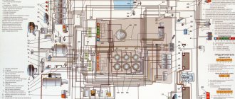
Electrical diagram of the ZIL-130 car
Electrical circuit diagram of the GAZ-31105 car with ZMZ-4062, ZMZ-40621 engines
The electrical equipment system of the ZIL-130 car is single-wire. The negative terminals of the current sources are connected to the vehicle ground. Rated voltage 12 V. The car uses low voltage wires of the PGVA type and high voltage wires of the PVV type.
Checking the wires for proper insulation is carried out by external inspection. If a bare spot is found on low voltage wires, it must be insulated (wrapped) with insulating tape. High voltage wires with broken insulation are replaced with new ones and cannot be repaired.
To determine whether a wire is broken, you need to use a probe with a control light. To identify the location of the break, a wire with a spring tip is connected to ground, and the tip of the tip begins to touch the circuit clamps in the direction from the non-working device to the battery. If there is a large distance between the terminals or if there are no terminals, you can pierce the wire insulation with the tip of the tip.
The check is carried out until the light comes on. The location of the wire break will be between the point of contact where the light bulb came on and the closest point to it where the light bulb is not yet on. The broken wire must be replaced. As a temporary measure, you can connect the ends of the broken wire and wrap the connection with insulating tape.
If the wire is shorted to ground, check the wire insulation. Since the circuit of many current consumers is protected by fuses, usually the circuit in which a short circuit occurs is immediately opened by the corresponding fuses.
To eliminate the short circuit, carefully inspect all wires and wrap any detected areas with damaged insulation with insulating tape.
To maintain the electrical wiring in good condition and prevent chafing of the wires, it is necessary to clean the wires from dirt and dust and check the wire fastening brackets.
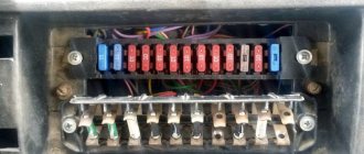
Circuit breakers
The following fuses can be installed in the electrical system of ZIL 131 and 130 vehicles:
p, blockquote 3,0,1,0,0 —>
- 20 A bimetallic fuse with automatic closure in the external lighting and instrument lighting circuits, located on the central light switch (under the dashboard);
- 20 Amp fuse with automatic closing for horn and portable lamp circuits; installed on a separate panel behind the cab shield on the left;
- fuse box with automatic closure (two fuses of 6/7.5A each) in the power supply circuits of the heater motor, instrumentation and turn signal switch; installed on the same panel as the horn fuse (was not present on earlier years of production).
See the diagram for more details.
p, blockquote 4,0,0,0,0 —>
Connection of lighting and alarm system devices
Construction machines and equipment, reference book
Electrical diagram of a VAZ 2115 car
Category:
Electrical equipment of cars
All devices of the lighting and light signaling system are connected to each other and to the current source by wires using a single-wire system, in which the second wire is the metal parts of the car - ground.
For ease of installation, the wires have different colors. Wires going in one direction are combined into bundles with a common protective sheath. The beams are attached to the car chassis with brackets. The wires are connected to each other by intermediate blocks with terminals.
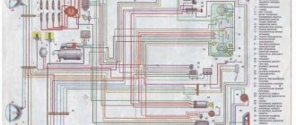
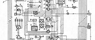
The diagram of the lighting and light signaling system of the ZIL-130 car is shown in Fig. 1. The system includes: two headlights with dual-filament low and high beam lamps; two sidelights with double-filament lamps for side lights and direction indicators; connection terminal blocks 3; rear lights with taillights and brake and turn signal lamps; cabin light; engine compartment lamp; plug socket for a portable lamp; trailer socket; instrument lighting lamps; indicator lamp 46 of the direction indicator; high beam indicator lamp; main light switch; foot light switch; lamp switch; turn signal switch with breaker and warning lamp; brake light switch; thermal bimetallic fuses. The lighting system is powered by common current sources: a generator and a battery, connected to the lighting system through the regulator terminals, ignition switch terminals, battery charging indicator lamp, starter traction relay terminal and auxiliary relay terminal. The turn signal switch is connected to power sources through the ignition switch and operates only when the ignition is turned on.
Rice. 1. Diagram of the ZIL-130 car lighting system
The electrical circuit for the headlight is as follows. When powered by battery: positive battery terminal - wire - starter traction relay terminal - wire - starter auxiliary relay terminal 14 - wire - ignition switch terminal - thermobimetallic push-button fuse terminal 26 - thermobimetallic fuse - main light switch - wire - foot switch - wire - headlight bulb filament - ground - negative battery terminal.
When powered from a generator, the current first flows through the following circuit: positive brush and terminal I of the generator - wire - terminal I of the relay-regulator - windings of the current limiter and reverse current relay - terminal B of the relay-regulator - wire - terminal of the starter traction relay and so on same path as for battery. Passing through the filament coil of the lamp to ground, the current returns to the generator through its negative brush. Through a similar circuit, the current flows to other light points.
Disassembling the starter
The starter must be disassembled in the following order.
- Unscrew the nut and disconnect the lead from the starter relay bolt.
- Unscrew the three screws and remove the casing.
- Unscrew the screws securing the relay yoke to the starter cover and remove the relay.
- Remove the brushes from the brush holder.
- Unscrew the starter tie rods.
- Remove the cover from the commutator side, having first disconnected the insulated brushes from the brush holders.
- Remove the starter housing.
- Unscrew the nut securing the lever axle, unscrew the axle and remove the lever.
- Remove the armature and drive assembly from the cover on the drive side.
- Remove the thrust washer from the armature shaft and, moving the thrust ring to the right, remove the locking ring from the shaft using a screwdriver, then remove the armature from the shaft.
- To inspect the contacts of the traction relay, unscrew the nut from the output bolt of the relay windings and the nut from the contact bolt; Unscrew the three screws securing the contact cover and remove the plunger along with the contact disk.
Modification Policy
Having such serious support and recognition, the car plant has received orders for modifications of the ZIL 130 since 1967. Two areas should be especially highlighted:
- Release of models capable of serving in the Arctic (at temperatures below -45C). These cars were produced for the development of fields in Siberia and the Far East;
- Release of models designed to work in the tropics (at 100% humidity). They were produced for foreign countries, which were helped by the Soviet government.
Photo of a poster from the 60s: ZIL-130 in tropical design
Modification ZIL 130S
In the 70s, many mineral deposits were discovered in Siberia. The cost of extraction was low, and their development required trucks capable of operating in harsh climate conditions.
For the North, ZIL instructions provided for an orange color - for greater visibility during snowfalls
You can judge the difficulties cars faced in the Far North from the video presented in our article. This black and white copy, recreated from archival materials of the Likhachev Plant, clearly demonstrates the capabilities of the ZIL 130 S truck.
Watch the thematic video at the end of the article.
Among the equipment of the ZIL 130S (Siberia), the following electrical equipment features should be noted:
- Pre-heater with autonomous power supply;
- Cabin with double glazing and additional auxiliary heater equipped with a high-power electric fan;
- Fog lights and searchlight with control from the cabin;
- Two independent gas tanks with a fuel level indicator on the dashboard;
- Battery electrolyte temperature indicator.
The pre-start heater ensured engine starting at sub-zero temperatures
Special versions
Also, cargo modifications differed by customer:
- For the Ministry of Defense (MoD);
- For emergency services (mainly firefighters);
- For civilian enterprises.
In particular, for army needs, the automobile plant began producing the ZIL-130E car, for which:
- shielded electrical wiring ZIL 130 was installed;
- alternating current generator G-51 (450 W power and current 40A);
- voltage regulator relay PP-51;
- ignition distributor-distributor R-102;
- high-voltage ignition coil B-102B;
- electric starter ST-2;
- spark plugs CH-307.
Monument on the territory of the Ministry of Emergency Situations in Belgorod, installed with your own hands
conclusions
ZIL 130 is a car with a rich history, which became the ancestor of many modern special equipment. Its design turned out to be successful for the construction of new modifications, and the main components and electrical equipment made it possible to operate the car in any weather.
Many questions are asked regarding the installation of the connection diagram for ZIL bull coils. Therefore, I had to mold the turn signal harness from the old harness
By the color of the thread it is easy to understand where it goes and what thread it is.
The turn signals themselves were not inserted and you can guess that they are connected to the connectors.
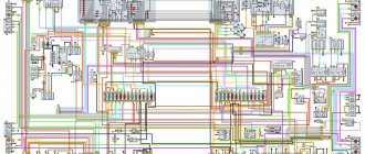
Rice. 1. Electrical diagram of direction indicators and signaling ZIL-5301 (Bull).
The scheme includes:
1. Relay 572.37777 Analogue 12V RS 950P.
Installed on the right side of the instrument panel on the rear side next to the bimetallic fuses
2. Turn on the steering column TU 37.003 1336-87.
3. Panic button 245.3710
4. On the left behind the dashboard there is a PR119-01 type 6A fuse.
If the turn signals fail, the first thing you need to look at is this fuse.
1.10, 23 and 48 - connecting panels; 2 - lighthouse; 3 - headlight; 4 — side turn signal repeater; 5 - generator; 6 — spark plug with noise-reducing resistor; 7 — sensor-distributor; 8 — sensor for emergency liquid overheating indicator; 9 - electrical signal; 11 - snack; 12 — starter relay; 13 — coolant temperature sensor; 14 — additional resistance of the ignition coil; 15 — engine compartment lamp; 16 - high voltage cables; 17 — ignition coil; 18 — identification lights of a road train; 19 - fuse; 20 - bimetallic fuse; 21 — bimetallic fuse block; 22 — direction indicator relay switch; 24 — ignition and starter switch; 25 — speedometer; 26 — high beam indicator; 27 — brake system pressure gauge; 28 - voltage regulator; 29 — heater electric motor; 30 — resistance of the heater electric motor; 31 — heater switch; 32 — switch for truck identification lights; 33 - ceiling switch; 34 - central light switch; 35 - ceiling; 36 — alarm indicator for emergency drop in oil pressure; 37 — instrument panel; 38 — turn signal indicator; 39 — contact devices for sound signal; 40 — direction indicator switch; 41 — emergency liquid overheating indicator; 42 — portable lamp socket; 43 — foot switch for headlights; 44 - transistor switch; 45 - battery; 46 — brake signal switch; 47 — fuel level indicator sensor; 49 — rear light; 50 - trailer socket
Categories
Archives
Foam generator for applying active foam to cars, price 5
An easy way to sharpen a drill
Tie the rope in a loop. We'll tear it apart to test its strength.
Lathes. Prices.
Choose a car in Russia
Choose a car in Ukraine
Gifts for real men
A practical guide to arc welding. Learn how to make beautiful, strong seams
2 tons for 8 dollars
Make a pyrolysis boiler with your own hands. Instructions, drawings, help.
This is where professionals are born. Hobbies, lathes, greenhouses. Share what we have in common
Historical excursion
It is quite logical that it was decided to unify the plant’s past developments, namely components from heavy trucks, as much as possible with the new class:
- The ZIL 5301 was equipped with a cabin of type 4331;
- The transmission used a ZIL 130 gearbox.
In 1995, a pilot batch of 200 cars was produced, which began full-scale tests, and a video about the new model immediately spread across all the country's news channels:
- At the end of the year, the result of the run-in was considered successful;
- The "Mercedes chassis" concept is approved as a platform;
- The base model of the van was the ZIL-5301 with a three-section body with a volume of 15.5 cubic meters;
- The ZIL 5301 series received its own name “Bychok”, because of the cabin with high headlights that resembled the outline of an animal;
- In 1996, the production of "Bulls" amounted to 1,350 cars.
The designers tried to unify the details of the new truck as much as possible