KAMAZ engine fuel pump, turning on the pump
_________________________________________________________________________________________
Design and details of the fuel system of the Kamaz-740 engine
The fuel supply system (fuel system) of KamAZ-740 ensures fuel purification and its uniform distribution among the engine cylinders in strictly metered portions.
Kamaz-740 engines use a split-type fuel supply system, consisting of a high-pressure fuel pump, injectors, coarse and fine filters, a low-pressure fuel booster pump, low- and high-pressure fuel lines, fuel tanks, a solenoid valve and flare spark plugs for an electric torch starting device.
A schematic diagram of the Kamaz-740 fuel system is shown in Fig. 1. Fuel from tank 1 through a coarse filter 2 is sucked in by the fuel priming pump and through a fine filter 17 through low pressure fuel lines 3, 9, 15, 21 and supplied to the high pressure fuel pump; According to the operating order of the engine cylinders, the pump distributes fuel through high-pressure pipelines 6 to injectors 5.
Rice. 1. Diagram of the fuel system of the Kamaz-740 engine
1 — fuel tank; 2 — fuel coarse filter; 3-fuel pipe supplying the low pressure pump; 4 — fuel drainage pipe of the left head injectors; 5 - nozzle; 6 — high pressure fuel pipe; 7 — low pressure fuel priming pump; 8 — manual fuel priming pump; 9 — fuel outlet pipe of the low pressure pump; 10 — high pressure fuel pump; 11 — electromagnetic valve; 12-fuel pipe to the solenoid valve; 13 — torch candle; 14 — fuel drain pipe for right-hand injectors; 15 — fuel injection pipe; 16 — fuel outlet pipe of the injection pump; 17 — fine fuel filter; 18 — fuel fine filter tube; 19 — tee for fastening fuel pipes; 20 — fuel drain pipe; 21 – fuel line to the coarse filter; 22 — receiving pipe with filter
Kamaz-740 injectors spray and inject fuel into the combustion chambers. Excess fuel, and along with it the air that has entered the Kamaz-740 fuel system, is discharged into the fuel tank through the bypass valve of the high-pressure fuel pump and the fine filter nozzle valve through fuel drain lines 16 and 18.
The fuel that has leaked through the gap between the nozzle body and the needle is drained into the tank through fuel drain lines 4, 14, 20.
The coarse filter (sump) Kamaz-740 (Fig. 2) pre-cleanses the fuel entering the low-pressure fuel priming pump.
Rice. 2. Coarse fuel filter Kamaz-740
1 – plug; 2 – glass; 3 – pacifier; 4 – filter mesh; 5 – reflector; 6 – distributor; 7 – bolt; 8 – flange; 9 – sealing ring; 10 – body
The coarse filter is installed on the suction line of the Kamaz-740 power system on the left side of the vehicle on the frame. Glass 2 is connected to body 10 with four bolts 7 and sealed with ring 9.
A drain plug 1 is screwed into the bottom of the cap boss. The fuel coming from the fuel tank through the supply fitting flows into the glasses.
Large particles and water collect at the bottom of the glass. From the upper part, through filter mesh 4, fuel is supplied to the fuel priming pump through the outlet fitting and fuel lines.
The Kamaz-740 fine filter (Fig. 3), which finally cleans the fuel before entering the high-pressure fuel pump, is installed at the highest point of the Kamaz-740 power system to collect and remove into the tank the air that has entered the power system along with part of the fuel through the valve - jet installed in housing 1.
Rice. 3. Fine fuel filter Kamaz-740
1 – body: 2 – bolt; 3 – sealing washer; 4 – plug; 5, 6 – sealing gaskets; .7 – filter element; 8 – cap; 9 – filter element spring; 10 – drain plug; 11 – rod
The beginning of the shift of valve-nozzle 4 (Fig. 4) occurs at a pressure in the cavity of 24.5... 44.1 kPa (0.25... 0.45 kgf/cm2), and the beginning of the fuel bypass from cavity A to cavity B - at a pressure in the cavity A 196.2... 235.3 kPa (2.0... 2.4 kgf/cm2). The valve is adjusted by selecting adjusting washers 1 inside the valve plug.
Rice. 4. Valve-nozzle for fine fuel filter KamAZ-740
1 — adjusting washer; 2 — valve plug; 3-spring; 4 - jet valve
Kamaz-740 fuel lines are divided into low pressure fuel lines of 392... 1961 kPa (4... 20 kgf/cm2) and high pressure of more than 19614 kPa (200 kgf/cm2).
The high-pressure fuel lines of the Kamaz-740 fuel system are made of steel tubes, the ends of which are made cone-shaped, pressed with union nuts through washers to the conical sockets of the fuel pump fittings and injectors. To avoid damage from vibration, the fuel lines are secured with brackets and brackets.
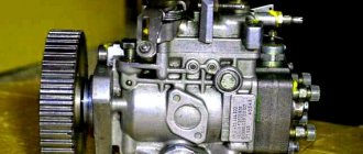
Fuel injection pump Kamaz-740
The Kamaz-740 high-pressure fuel pump (HFP) is designed to supply strictly dosed portions of fuel under high pressure to the engine cylinders at certain times.
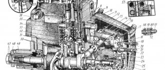
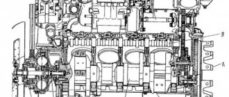
Eight sections are installed in the Kamaz-740 injection pump housing (Fig. 5), each consisting of a housing 17, a sleeve 16 of a plunger 11, a rotary sleeve 10, a discharge valve 19, pressed through a sealing gasket 18 to the plunger sleeve by a fitting 20. The plunger performs a reciprocating movement under the action of the cam shaft 44 and spring 8.
Rice. 5. Fuel pump TNVD Kamaz-740
1 - body; 2, 32 — pusher rollers; 3, 31 — roller axes; 4 - roller bushing; 5 — pusher heel; 6 - cracker; 7 — pusher spring plate; 8 — pusher spring: 9,34,43,45, 51 — washers; 10 — rotary bushing; 11 - plunger; 12, 13, 46, 55 — sealing rings; 14—locating pin; 15 - rack; 16 — plunger bushing; 17 — section body; 18 — discharge valve gasket; 19 - discharge valve; 20 - fitting; 21 — section housing flange; 22 — manual fuel priming pump; 23 — spring plug; 24, 48 — gaskets; 25 - low pressure pump housing; 26 — low pressure fuel priming pump; 27 — rod bushing; 28 — pusher spring; 29 — pusher; 30 — locking screw; 33, 52 — nuts; 35 — low pressure pump drive eccentric; 36, 50 — keys; 37 — flange of the regulator drive gear; 38 — holder of the regulator drive gear; 39 — regulator drive gear; 40 — thrust bushing; 41, 49 — bearing caps; 42 — bearing; 44 — cam shaft; 47 — cuff with spring assembly; 53 — fuel injection advance clutch; 54 — rack plug; 56 — bypass valve; 57 — rack bushing; 58 — rack lever axis; 59 — adjusting gaskets
The pusher is secured against rotation in the body of the Kamaz-740 injection pump fuel pump by a cracker 6. The cam shaft rotates in roller bearings 42 installed in the covers and attached to the pump body. The axial clearance of the cam shaft is adjusted by shims 48. The clearance should be no more than 0.1 mm.
To increase the fuel supply, the plunger 11 is rotated by a sleeve 10 connected through the axis of the driver to the pump rack 15. The rack is mixed in the guide bushings 57. Its protruding end is closed with a plug 54.
On the opposite side of the Kamaz-740 injection pump there is a screw that regulates the fuel supply by all sections of the pump. This screw is capped and sealed.
Fuel is supplied to the Kamaz-740 high-pressure fuel pump through a special fitting, to which a low-pressure pipe is bolted. Then, through the channels in the body, it flows to the inlet holes of the 16 plunger bushings.
A bypass valve 56 is installed at the front end of the Kamaz-740 fuel injection pump housing and at the fuel outlet, which opens at a pressure of 58.8... 78.5 kPa (0.6... 0.8 kgf/cm2).
The valve opening pressure is regulated by selecting shims inside the valve plug. The pump is lubricated by circulation, under pressure from the general engine lubrication system.
The turbocharged engine is equipped with a Kamaz-740 TNVD 334 fuel pump with increased injection energy, with an anti-smoke corrector and a nominal cyclic fuel supply of 96 mm3/cycle.
The rotation speed regulator of the Kamaz-740 injection pump is all-mode, direct-acting, changes the amount of fuel supplied to the cylinder depending on the load, maintaining a given frequency.
The regulator is installed in the housing casing of the Kamaz-740 high-pressure fuel pump. The drive gear 21 of the regulator is installed on the cam shaft of the Kamaz-740 injection pump fuel pump, rotation to which is transmitted through rubber nuts 22. The driven gear is integral with the weight holder 9, rotating on two ball bearings.
When the holder rotates, the weights 13, swinging on the axes 10, diverge under the action of centrifugal forces and move the clutch 12 through the thrust bearing 11. The clutch, resting against the pin 14, in turn moves the lever 32 of the weight clutch.
Lever 32 is fixed at one end to axis 33, and at the other end it is connected through a pin to rack 27 of the Kamaz-740 injection pump. A lever 31 is fixed to the axis 33, the other end of which moves all the way to the fuel supply adjusting bolt 24. Lever 32 transmits force to lever 31 through corrector 15.
Fuel supply control lever 1 (Fig. 7) is rigidly connected to the lever. A spring 26 is attached to the levers 20, 31, and a starting spring 28 is attached to the levers 25, 30. During operation of the regulator in a certain mode, the centrifugal forces of the loads are balanced by the force of the spring 26.
Rice. 7. Cover of the Kamaz-740 speed controller
1 - fuel regulator control lever; 2 — bolt for limiting the minimum rotation speed; 3 — stop lever; 4 — filler plug; 5 — starting feed adjustment bolt; 6 — bolt for limiting the travel of the stop lever; 7 — bolt for limiting maximum rotation speed; I - work; II - off
When the speed of rotation of the crankshaft of the regulator increases, overcoming the resistance of spring 26, the weights move lever 32 of the Kamaz-740 injection pump regulator - the fuel supply decreases.
As the crankshaft rotation speed decreases, the centrifugal force of the loads decreases, and the regulator lever 32 with the fuel pump rack moves in the opposite direction under the action of the spring force—the fuel supply and the crankshaft rotation speed increase.
The fuel supply is turned off by turning stop lever 3 (see Fig. 7) until it stops against bolt 6, while lever 3, overcoming the spring force, turns levers 31 and 32 through pin 29; the rack will move until the fuel supply is completely turned off.
When the force is removed from the stop lever, under the action of the spring, the lever will return to the operating position, and the starting spring 16 through the lever 30 will return the fuel pump rack to the position of the maximum fuel supply required for starting.
Low pressure fuel pump and fuel priming pump Kamaz-740
The Kamaz-740 low-pressure piston-type fuel pump is designed to supply fuel from the tank through a coarse and fine filter to the inlet cavity of the high-pressure pump. The pump is installed on the rear cover of the regulator.
A piston, a piston spring, a rod bushing 27 and a pusher rod are installed in the housing 25 (see Fig. 5), and an inlet valve and a valve spring are installed in the housing flange. The eccentric of the cam shaft, through roller 32, pusher 29 and rod, imparts reciprocating movement to the piston of the fuel priming pump.
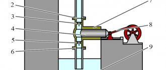
The operating diagram of the Kamaz-740 low-pressure injection pump is shown in Fig. 8. When the pusher is lowered, the piston 10 moves downward under the action of the spring 4. A vacuum is created in suction cavity A, and inlet valve 1, compressing spring 2, allows fuel into the cavity.
Rice. 8. Scheme of operation of the low pressure fuel pump and manual fuel priming pump Kamaz-740
1 — inlet valve; 2, 4, 5, 9 — springs; 3 — piston of the manual fuel priming pump; 6 — pusher; 7 - eccentric; 8 — discharge valve; 10 - piston; A - suction cavity; B - injection cavity: C - supply to the fuel injection pump Kamaz-740; E - supply from the coarse fuel filter
At the same time, the fuel located in the discharge cavity B is forced into the line, bypassing the discharge valve 8, connected by channels to both cavities. In the free position, the discharge valve closes the channel of the suction cavity.
When the piston 10 moves upward, the fuel that has filled the suction cavity enters the cavity B under the piston through the discharge valve 8, and the inlet valve 1 closes.
When the pressure in the discharge line increases, the piston does not make a full stroke following the pusher, but remains in a position that is determined by the balance of forces from the fuel pressure on one side, and from the spring force on the other side.
The Kamaz-740 fuel priming manual pump fills the system with fuel and removes air from it. The piston type pump is mounted on the low pressure fuel pump flange with a copper sealing washer.
The Kamaz-740 fuel priming pump consists of a housing, a piston, a cylinder, a handle assembly with a rod, a support plate and a seal. The Kamaz-740 power system is pumped by moving the handle with the rod and piston up and down. When the handle moves upward, a vacuum is created in the sub-piston space.
Inlet valve 1, compressing spring 2, opens, and fuel enters cavity A of the low-pressure fuel pump. When the handle moves down, the discharge valve 8 opens and fuel under pressure enters the discharge line.
After pumping, screw the handle onto the upper threaded shank of the cylinder. In this case, the piston will press against the rubber gasket, sealing the suction cavity of the low pressure fuel pump.
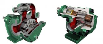
The Kamaz-740 automatic fuel injection advance clutch (Fig. 9) changes the start of fuel supply depending on the engine crankshaft speed.
Rice. 9. Automatic fuel injection advance coupling KamAZ-740
1 — driving coupling half; 2.4 - cuffs; 3 - bushing of the driving coupling half; 5 — body; 6-adjusting gaskets; 7 — spring cup; 8 - spring; 9, 15 — washers; 10 - ring; 11 — weight with a finger; 12 — spacer with axle; 13 — driven coupling half; 14 — sealing ring; 16 — weight axis
The use of a clutch ensures that the start of fuel supply is optimal for the work process over the entire range of speed modes. This ensures economy and acceptable rigidity of the process in various speed modes of engine operation.
The driven coupling half 13 is fixed on the conical surface of the front end of the cam shaft of the Kamaz-740 fuel pump with a key and a nut with a washer, the driving coupling half 1 is mounted on the hub of the driven coupling half (can be rotated on it).
A sleeve 3 is installed between the hub and the coupling half. The weights 11 swing on axes 16, pressed into the driven coupling half, in a plane perpendicular to the axis of rotation of the coupling.
Spacer 12 of the drive half of the coupling rests with one end against the load pin, and with the other against the profile protrusion. Spring 8 strives to hold the load against the stop in the sleeve 3 of the drive half-coupling.
As the crankshaft rotation speed of the KamAZ-740 increases, the loads diverge under the influence of centrifugal forces, as a result of which the driven coupling half rotates relative to the drive half in the direction of rotation of the cam shaft, which causes an increase in the advance angle of fuel injection.
When the crankshaft rotation speed decreases, the weights converge under the action of springs, the driven coupling half rotates together with the pump shaft in the direction opposite to the direction of shaft rotation, which causes a decrease in the fuel supply advance angle.
Injector Kamaz-740
The Kamaz-740 nozzle (Fig. 10) is a closed type with a multi-hole nozzle and a hydraulically controlled needle. All nozzle parts are assembled in housing 6.
Rice. 10. Kamaz-740 nozzle
1- spray body; 2-nozzle nut; 3 — nozzle spacer; 4—locating pins; 5 – nozzle rod; 6 — nozzle body; 7 - sealing ring; 8 - fitting; 9, 10 – adjusting washers; 11 – nozzle spring; 12
A spacer 3 and a spray body 1, inside of which there is a needle, are attached to the lower end of the nozzle body with a nut 2. The body and the atomizer needle form a precision pair.
The sprayer has four nozzle holes. Spacer 3 and body 1 are fixed relative to the body with pins. Spring 11 rests against rod 5 at one end, which transmits force to the spray needle, and at the other end - against the stop.
Fuel is supplied to the Kamaz-740 injector under high pressure through fitting 8. Then, through the channels of body 6, spacer 3 and body 1 of the nozzle, fuel enters the cavity between the nozzle body and the needle and, squeezing it out, is injected into the cylinder.
The fuel that has leaked through the gap between the needle and the nozzle body is discharged through the channels into the nozzle body. The Kamaz-740 injector is installed in the cylinder head and secured with a bracket. The end of the nozzle nut is sealed against gas breakthrough with a corrugated washer.
The O-ring protects the cavity between the injector and the cylinder head from dust and water. The turbocharged Kamaz-740 engine has a model 271 injector with increased fuel throughput and a nozzle hole diameter of 0.32 mm.
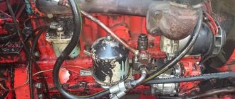
Kamaz-740 fuel supply control drive
The Kamaz-740 fuel supply control drive (Fig. 11) is mechanical, with a telescopic pusher, and consists of a pedal, rods, levers and transverse rollers.
There is also a manual drive for fuel supply and engine stop. The fuel supply pedal 13 is connected to the speed controller control lever 7.
Rice. 11. Kamaz-740 fuel supply control drive
1 — engine stop handle; 2 — handle for manual fuel supply control; 3, 10 - rear levers; 4 — rod of the regulator control lever; 5 - injection pump; 6 — engine stop lever; 7-regulator control lever; 8 - transverse roller; 9 — rear bracket; 11- telescopic rod; 12 — pedal bracket; 13 - pedal; 14 - adjusting bolt
The remote control rod handles for the Kamaz-740 engine are installed in the cab on a bracket at the bottom of the panel: left 2 - to turn on a constant fuel supply, connected by a flexible cable in a protective sheath to the speed control control lever; right 1 - to stop the engine, connected by a cable to the engine stop lever, which is located on the cover of the speed controller.
_________________________________________________________________________________________
_________________________________________________________________________________________
_________________________________________________________________________________________
_________________________________________________________________________________________
_________________________________________________________________________________________
_________________________________________________________________________________________
_________________________________________________________________________________________
_________________________________________________________________________________________
_________________________________________________________________________________________
_________________________________________________________________________________________
DIY pump repair
Manufacturers have declared the mileage of a new KamAZ vehicle (Euro 3) to be at least 800 thousand km. However, difficult operating conditions, overloads and sudden temperature changes make their own adjustments. In practice, the pump can withstand 50–60 thousand km. This assumes that regular maintenance is carried out. The main malfunctions of the water pump 740.63–1307040 are considered:
- chips and cracks in the pump body;
- bending or wear of the working shaft;
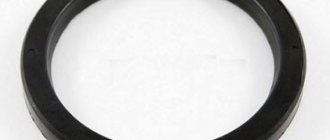
- wear of the sealing gland;
- bearing wear.
The quality of the coolant plays a huge role in the proper operation of the water pump. As you know, antifreeze is designed for 30 thousand kilometers or 2 years of continuous operation. After the stated period, the properties of the antifreeze change dramatically. This is especially reflected in the lubricating and anti-corrosion properties. The constantly wetted impeller and radiator become covered with rust, flakes of which clog the ducts and rubbing areas. This leads to premature wear of the entire cooling system.
The good news for the motorist is that pumps of this type are available for repair. They can be easily and completely disassembled and contain no irreplaceable parts.
Chips, cracks and other mechanical damage to the housing (or impeller) are eliminated using electric welding or two-component sealants (such as epoxy resin). A bent impeller rotation roller can often be leveled with a press or by applying a layer of chromium (followed by fine-tuning it to standard dimensions). Only the sealing seal cannot be repaired, which is quite easy to remove and replace.
Diagnosing problems in the cooling system
Before you begin repairing the water pump, you need to make sure that the cause of the engine malfunction lies precisely in it.
The main indicator by which one can judge a malfunction of the cooling system is an increase in engine temperature during operation. The temperature indicator shows the engine temperature above 100 o C.
Location of the temperature sensor indicator on the KamAZ dashboard
There may be several reasons:
- low coolant level, coolant leak;
- malfunction of the thermostat;
- malfunction of the radiator;
- water pump failure.
It is easy to establish the fact of a coolant leak by looking at the expansion tank - there are marks on it for the maximum and minimum amount of antifreeze in the system. If the level is below the minimum, it means there is a leak somewhere that needs to be found.
If the thermostat breaks down (and there are two of them in KamAZ 5511), as a rule, the fluid temperature drops below the average value. This is due to the fact that a large cooling circle is constantly turned on. This is also harmful to the engine, but overheating does not occur. If the thermostat is stuck in the “small circle” position, which is extremely rare, the first sign is a complete shutdown of the heating in the cabin. The coolant boils right in the expansion tank.
The radiator may either leak or become clogged. A large amount of dirt and dust adhering to the front of the radiator often leads to overheating of the engine. After washing the honeycombs, the situation usually returns to normal.
If all of the above units are working properly, but the indicator still shows an increased engine temperature, it is worth inspecting the water pump. Experienced motorists use several simple but true tests:
- A damaged pump begins to make a characteristic sound. The tone changes with increasing speed, moving from a low “howl” to a high-pitched “squeal”.
- Formation of liquid leaks in the area of the water pump. They are not always obvious; fluid oozes only at high crankshaft speeds. But an experienced eye will immediately notice specific dirty-brown marks on the surface of the cylinder block. The reason is a breakdown of the oil seal.
- The third way to determine the malfunction is to manually rock the water pump pulley. To do this, you need to remove the drive belt(s) and try to swing the pulley up and down. If even the slightest play (0.5–1 mm) is observed, then there is wear on the shaft or bearing. They need to be changed.
In winter, an indirect sign that may indicate a pump failure may be low heating of the air in the cabin. Slow circulation of coolant leads to the fact that the stove does not cope with its task - it is cold in the cabin.
One of the reasons for premature wear of the bearing or drive shaft of the water pump can be excessive tension on the drive belt. It is recommended to check the tension force using a dynamometer or steelyard. After replacing or repairing the unit, it is necessary to correctly adjust the degree of belt tension.
Sometimes it happens that the pump is working properly (no noise, no shaft play or fluid leaks), but the sensor persistently indicates overheating of the motor. In this case, you need to check the functionality of the temperature sensor itself. If a malfunction is detected, replace it.