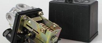
Device
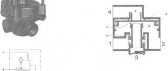
The spring accumulator is mounted on the brake chamber cover and serves to accumulate the energy of the compressed spring.
The main parts of the device are:
- cylinder;
- piston;
- power spring;
- pusher;
- thrust bearing;
- release screw with roller bearing;
- bypass tube;
- seals.
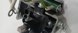
The battery is attached to the camera using bolts, which ensures a strong connection and eliminates play during operation. The seal between the cylinder and the brake chamber is ensured by installing a rubber sealing ring. A nut for the screw of the brake release system is welded in the upper part of the housing. At the bottom of the cylinder there is a threaded fitting through which the pneumatic line is connected.
A tubular pusher is welded to a metal piston with a rubber sealing ring. The steel power spring is located in the piston groove and rests on the top of the cylinder. The pusher has a thrust bearing, which transmits force to the brake chamber rod through a membrane.
The screw is used for manual release in the event of a lack of compressed air in the system due to a compressor failure or a defective receiver. At the bottom of the screw there is a roller bearing and 2 thrust rings.
The cavity located above the piston communicates with the atmosphere via a bypass tube through the brake chamber. Air is supplied to the chamber under the piston from the parking brake control valve. All energy accumulators simultaneously participate in air analysis.
Reverse-acting pneumatic hand brake valve
Such a crane is used as a parking brake on vehicles of the KamAZ, ZIL, KrAZ, MAZ and Ural brands.
If there is a malfunction, the valve may leak air or the vehicle will slowly release the brakes. In this case, it will be necessary to replace the worn rubber o-rings and cuffs. This set is included in the RTI repair kit for the hand brake valve, has a catalog number 100-3537009-30 and the name “set of spare parts for the manual reverse-action brake valve”. The catalog number of the tap itself is 100-3537010.
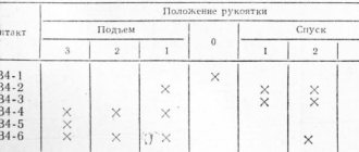
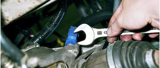
ADJUSTING THE TAP
We apply pressure to terminals 1 and 2 and try to move the lever all the way and back several times and see with what difference the air comes out at terminals 3 and 4 and with adjusting bolt 1 we adjust the air supply so that it comes out evenly to the front and rear axles. This way we will adjust the order in which the brakes are applied.
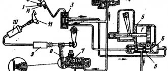
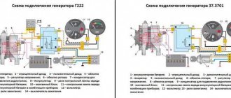
drive installation
connection diagram
Our company has its own fleet of cars. The completed goods will be delivered by transport to the address of the end consumer or to a transport company.
Delivery to the terminal of the transport company or to the buyer within the Moscow Ring Road is free.
Delivery of spare parts to the buyer within the Moscow region is free for orders over 200,000 rubles, within a radius of 500 km from the Moscow Ring Road - free for orders over 500,000 rubles.
Cash foreign currency is not accepted for payment.
The group offers to purchase MAZ spare parts wholesale and small wholesale at the best price in Rostov-on-Don and other cities of Russia.
You are in the “MAZ Brake System” section. On this page you have the opportunity to buy the part Hand brake valve (4 holes) (PAAZ) article number 11.3537310. To do this, you just need to indicate the quantity you want and fill out an application. Your order will be executed in the shortest possible time.
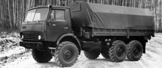
Rules for the operation and repair of energy accumulators for KamAZ vehicles
The KamAZ vehicle has a dual-circuit pneumatic braking system, which ensures vehicle safety in all driving modes. During braking (when you press the brake pedal), compressed air is immediately supplied to the brakes of all wheels. The parking brake only locks the wheels of the middle and rear axle. The main element of the drive of such a brake is the energy accumulator. KamAZ has 4 such devices - 1 for each wheel of the rear bogie.
How to assemble a KAMAZ energy accumulator
The battery is assembled in the following order:
- A sealing washer is placed on the screw.
- The screw is screwed all the way into the cylinder, and a rubber ring is put on.
- The spring is installed in the cylinder so that the small coil is on the outside.
- The guide ring and seal are placed on the piston.
- The piston is installed on the spring so that its end rests against the boss.
- The flange is put on the piston pipe, before that the guide and sealing rings are inserted into it, and the sealing ring is put on.
- The assembled assembly is installed in the fixture so that the stop covers the screw head.
- Carefully rotate the handle, compressing the spring, until the flange makes contact with the cylinder, ensuring that the guide ring fits correctly into the cylinder.
- The cylinder and flange are connected using bolts.
- The assembled energy accumulator is removed and a support washer is installed on the screw.
- The stop and needle bearing are recessed beyond the rubber ring, installing the retaining ring so that it fits inside the helical groove as securely as possible. If compressed air is available, it can be supplied inside the spring energy accumulator. In this case, the screw shank will be closer to the edge of the piston tube, making installation of the thrust bearing easier.
- The screw is carefully unscrewed, checking that the piston is securely held by the locking ring. This action is repeated several times.
- The sealing ring is put on the pusher, which is wrapped into the piston tube.
- The pneumatic chamber body is connected to the flange with a clamp.
Principle of operation
Made to control the actuators of the working brake system of a car, ZIL-130, as well as to activate the control valves of the trailer brake system.
The brake valve is mounted on a bracket attached to the frame side member. The air exits the tap downward through terminal 5.
The brake valve has two independent sections arranged in series. Terminals 1 and 2 of the valve are connected to the receivers of the separate drives of the service brake system.
two-piece brake valve
The force from the brake valve lever is transmitted through the rubber elastic element 31 to the upper piston 30. Moving down, the piston closes the outlet hole of the valve 29 and then lifts it off the seat. Through output 3, compressed air enters the brake chambers of the rear wheels until the force of pressing the lever is balanced by the pressure of compressed air on the piston 30 from below.
Simultaneously with the increase in pressure in outlet 3, compressed air through channel A in the valve body enters cavity B above the large piston 28 of the second section of the brake valve. The piston, which has a large area, moves downward with a slight pressure in the above-piston space and acts on the small piston 15. As the piston moves, the outlet of the valve 17 closes, and then it comes off the seat. Compressed air through port 4 enters the brake chambers of the front axle wheels.
When the pressure in port 4, and consequently in cavity C under pistons 15 and 28, increases, the force acting on the pistons from above is balanced. Thanks to this, a pressure corresponding to the force on the brake valve lever is also established in pin 4 (following action).
If the circuit is damaged and if there is no pressure in output 3 of the first section, the force from the brake valve lever will be transmitted through the pin 11 directly to the pusher 18 of the small piston. Thus, the second section will be controlled mechanically, not pneumatically, and will remain fully operational.
If another circuit is damaged and if there is no air in terminal 4 of the second section, the first section works in the same way.
The drive of the two-section brake valve consists of a pedal connected by a rod to the brake valve lever. The required position of the pedal on the cabin floor is established by changing the length of the rod using a threaded fork. The pedal is returned to its original position by a spring.
PRINCIPLE OF OPERATION
disassembling the brake valve
ASSEMBLY OF ENERGY ACCUMULATOR
We take the repair kit, install all the cuffs in the order of assembly, most importantly, don’t forget to put something from the cuffs and crackers, otherwise you’ll have to disassemble them again later. When assembling, lubricate the cuffs with lubricant, preferably. The assembly process proceeds in reverse order. We put everything in place and tighten the piston with the cover with 4 bolts and tighten it slowly without distortion.
Repair kit
After everything has been pulled together, you need to install a retaining ring inside the pusher into the energy accumulator. We also attach the hose to the air of the car, place it on the handbrake and install the retaining ring. Select the appropriate size tube for the stopper. Well, everything is assembled, all that remains is to install it on the car.
Energy accumulator assembly
After assembly, check it for air etching; if the cuff is etching, you will immediately hear the hiss of air, test it several times to see if it works and then install it on the car. In this simple way, we sorted out the energy accumulator ourselves at home; every driver can do this.
WATCH THE VIDEO
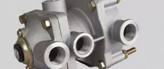
Features of the MAZ parking brake valve
The part is used for:
- Supplying compressed air to the energy accumulator in order to release the brakes of the machine;
- To release compressed air completely when putting the handbrake on;
- Bleeding air partially for the operation of auxiliary or spare brakes;
- Monitoring the operation of the parking brake in a road train.
When the handle is in a horizontal position, the MAZ parking brake is turned off. When moving to a horizontal position, the wheels are braked, and in the middle position partial braking occurs.
How to repair the MAZ parking brake valve?
The faulty element allows air to pass through, causing the car to release the brakes more slowly. To solve the problem, you need to replace worn o-rings and cuffs. Everything you need is included in the handbrake valve repair kit.
To repair or replace the unit, you need to remove the part from the bracket. To do this you need:
- Find the tap to the left of the driver's seat;
- Unscrew the 3 pneumatic tubes;
- Press the cover to the body and remove the screws;
- Knock out the notched part of the pin;
- Extend the rod and remove the pin;
- Move the washer and guide cap;
- Remove the retaining ring, valve outlet seat, spring, and guide.
Then the spring is dismantled along with the plate, the fitting is turned out and the follower piston is squeezed out.
To remove the retaining ring, press on the valve body. Next, all that remains is to replace the damaged components and reassemble in the reverse order. Rings and cuffs should be selected taking into account the size of the knot.
On our website you can buy a MAZ parking brake valve for trucks. We guarantee fast delivery to any city in Russia, as well as the best prices for the entire range of components.
Repair of the parking brake valve (replacement of rubber sealing rings and cuffs)
To repair the handbrake valve, you will need to remove it from the bracket on which it is installed. On KamAZ and ZIL vehicles the tap is located to the right of the driver's seat. On MAZ cars - on the left.
1. The faucet is attached to the bracket with two bolts and three pneumatic tubes are connected to it, which must be unscrewed first.
2. Now carefully remove the tap cover so as not to lose the spring and rollers. To do this, pressing it against the valve body, unscrew two screws, which are also the axes of the rollers.
3. If the rollers are stuck, pry them off with a screwdriver.
4. The distortion of the cover should be removed using adjusting shims. The cover should move relative to the body without jamming. If the end of the cover is worn, the number of shims should be increased.
5. Knock out the notched part of the pin.
8. Using side cutters, pull out the valve exhaust seat rod and remove the pin.
9. Slide the guide cap and washer off the rod.
10. While pressing on the rod guide, remove the retaining ring.
11. Remove the valve outlet seat, spring and stem guide.
12. Take out the balancing spring with the plate.
In some taps, there may be washers between the plate and the balancing spring that regulate its stiffness. Their reverse installation is required.
13. Using a 19mm wrench, unscrew the atmospheric outlet fitting.
14. Using a 10-11 mm rod, squeeze the follower piston out of the body.
15. Pressing the valve body, remove the retaining ring.
16. Remove the valve and spring from the follower piston.
17. When the valve sealing ring wears out, air from the pneumatic system will escape through the atmospheric outlet in any position of the handle. The same thing will happen with a torn valve cuff.
18. To replace it, remove the support washer.
19. Carefully remove the edge of the cuff from the annular groove of the valve and remove it from the seating collar.
The edges of the groove and seat collar may be sharp. They must be smoothed before installing a new cuff. If the old cuff was removed without damage, it can be used again by turning it 180 degrees.
20. Leakage of the ring sealing the stem of the exhaust valve seat causes air leakage from the side of the valve cover during the parking brake release mode.
With a properly fitted O-ring, the valve seat stem should move in the guide with little force. If this cannot be achieved, replace the rod guide with a new one.
21. Sometimes there are taps with an additional valve section. If the tightness of its valve or seals is broken, air hisses from the side of the boot or from the atmospheric outlet.
To replace the valve, use a 19 mm wrench to unscrew the valve spring support fitting. We remove the valve assembly and replace it if necessary.
How to disassemble a KAMAZ energy accumulator
Repair of a KAMAZ energy accumulator is necessarily preceded by cleaning, washing and drying it.
How to sort out a KAMAZ energy accumulator? Before disconnecting its lower part from the middle part, it is necessary for air to enter the chamber related to the parking brake; the pressure must be at least 5 atm. This will allow the operating rod to sink and prevent the spring from firing. Then the clamp is removed and the diaphragm is removed.
Then the air supply is turned off, the plug of the operating rod is unscrewed using key number 36. Air is again supplied inside the parking brake chamber. The rod contains a limit bolt that has a support bearing secured with a retaining ring.
During further resuscitation of the KAMAZ, the retaining ring is removed with an awl and the rod is released for subsequent disassembly. Then an operation is performed that requires the use of either a hydraulic press or a special clamp. Pressing the rod using a press or clamp prevents the spring associated with the parking brake from firing. Then the bolts securing the upper glass to the middle part are unscrewed.