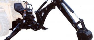
Choosing a crane installation is not an easy task. There are many models, variants and options available on the market, from which you can create a configuration that is optimal for almost any specific job. However, in order to make the right choice, you need to have a good understanding of this diversity. For example, specialists from a KAMAZ dealer, HIAB, FASSI, Palfinger, UNIC, DongYang, BAKM manipulators, which manufactures and sells vehicles with manipulator cranes: flatbed vehicles, tractors, dump trucks, cars with vans, etc., will help you make this difficult decision. The wide variety of this technology and the lack of information on its use for different technological processes confuse the consumer. The specialists of JSC Avtobau, relying on their extensive experience in the manufacture of various equipment with cranes, will help you decide on the choice of vehicles with a hydraulic drive necessary to perform specific tasks.
Of course, it is better to entrust the selection to a specialist, but the buyer must also understand the purpose of various crane equipment. We will try to introduce readers to the basic concepts in this area. First of all, let's define the terms.
In Russia, there is a division of lifting mechanisms of the type we are considering into cranes and hydraulic manipulators. Hydraulic manipulators (HM) work with hydraulic tools, usually with grabs (sometimes with drilling rigs) and are used for transshipment, i.e., reloading logs or scrap metal. This is a special regime of work with high intensity, approximately 1400 cycles per week. Hence, hydraulic manipulators are subject to increased reliability requirements. Another important requirement for them is a short cycle time. The load is almost always the same, i.e. the operations and movements of the hydraulic manipulator are monotonous. The main movement that allows you to quickly complete the cycle is the swinging movements of the first and second sections of the boom. Hence the design features: the first section is long, the second section is short with a small telescopic part (in order, if necessary, to move the load further than usual). Therefore, hydraulic manipulators cannot be folded behind the cabin, since they extend beyond the dimensions of the cabin; in the transport position they are simply placed on a special bracket either in front or turned backwards.
In recent years, foreign and domestic models of hydraulic manipulators have appeared that are capable of folding and fitting into the dimensions of a car - the so-called reverse Z-shaped folding pattern, when the last boom is located on top, and the grab is at the top and therefore can fit into the dimensions of the car. Such hydraulic manipulators have a small load moment and a limited scope of application.
Crane manipulator units (CMU) transport loads (usually construction) using a hook suspension, i.e., in the classic version, they do not have a hydraulic drive to the working element. CMUs are used less intensively (they placed the load on a car and drove it to a construction site), the main goal of the creators of the CMU was to ensure maximum load capacity and positioning accuracy with a minimum weight of the installation itself. For this purpose, the installation is equipped with high-precision, slow-operating hydraulics, which maximally compensates for the dynamic loads that arise during loading and unloading operations, and thereby increases the life of the CMU. Therefore, CMUs differ from hydraulic manipulators in having a longer operating cycle time.
The flow rates in the hydraulic system of these manipulators vary significantly: for hydraulic manipulators it is 70…90 l/min, and for CMU it is 10…45 l/min. But the pressure in the CMU hydraulic system is much higher: for hydraulic manipulators up to 20 MPa, for CMU from 25 to 33 MPa. In addition, hydraulic manipulators are even structurally less suitable for operations performed by hydraulic hydraulic manipulators. In terms of price, CMUs are usually up to 40% cheaper than hydraulic manipulators.
It can obviously be said that hydraulic manipulators and manipulator cranes have fundamental differences in both design and function. In the article we will call all installations of this type manipulators.
It should be noted that according to Russian legislation, forestry hydraulic manipulators do not require registration with Rostechnadzor. All other manipulators with a lifting capacity of more than 1 t and with a load moment of more than 4 t.m are subject to registration.
In the article we will mainly talk about the choice of CMUs as the most common manipulators.
CMU folding type
In Europe, CMUs of an articulated design with a Z-shaped folding pattern have become widespread. In the transport position, the boom is located in the transverse plane of the vehicle behind the cab. When installing a Z-shaped crane behind a truck cab, the entire weight of the crane falls on the front axle (i.e., it can be overloaded).
In Japan, South Korea and the USA, L-shaped cranes with a straight telescopic boom and a cable suspension of the load hook are more popular. They are typically used for loading and unloading the base vehicle and sometimes a trailer. For an L-type CMU, the boom is located above the body along or against the machine. Thus, it can interfere with the placement of a high load in the body and will not allow the load to be loaded “with a head”. But with this arrangement, the mass of the CMU is partially redistributed to the rear axle and does not load the front axle. The L-shaped crane has a long first boom section that cannot be folded, but short telescopic sections. Such a crane operates at long reach (6...8 m) faster than a Z-shaped one.
It is sometimes said that L-shaped CMUs, unlike Z-shaped ones, have fewer nodes and hinge joints, so their design is simpler and more reliable. This is not a completely fair statement. L-shaped CMUs have a rather complex design of the telescoping mechanism, so repairing the extension cylinders can be labor-intensive and costly.
A straight L-shaped boom cannot bypass an obstacle, such as a vertical wall, which a cranked Z-shaped “colleague” can easily overcome. However, there are booms that combine the advantages of L- and Z-shaped designs: their first two sections have a hinged connection, the subsequent sections are telescoped from the second. This type of crane has more degrees of freedom than a classic L-shaped one.
It is difficult to say for sure which of the structures is heavier - L- or Z-shaped. Due to the presence of "overlapping" sections, the telescopic boom of an L-shaped crane can be heavier than a Z-shaped one. However, in a Z-shaped boom with high lifting capacity, powerful connecting hinges can greatly weigh down the structure, so in each specific case, when choosing a crane, its weight should be considered separately.
The choice between a Z- and L-shaped crane is a rather delicate question; you need to calculate the price of both, its capabilities, the capabilities of the truck when installing one or another crane, and choose the option that is optimal in terms of price and capabilities. For example, a heavy Z-shaped crane requires a powerful (and expensive) chassis, but you can use a lighter (and cheaper) chassis by installing an L-shaped crane, but it will hang over the body, etc. L-shaped crane to increase g /p must constantly increase the angle of lift of the boom, thus, to carry a large load, a very long boom will be required. In Z-shaped CMUs, the load is lifted by folding and unfolding the sections. It is difficult for them to handle heavy loads near a column because once the boom is folded, it is difficult to unfold it. For this reason, Z-shaped cranes have a hook suspension at the base of the second section, which is used for lifting heavy loads, with only the first section working. Therefore, an L-shaped crane handles better heavy but compact loads, while Z-shaped cranes work better with large loads.
In general, L-shaped hydraulic units are more highly specialized (for example, if a truck with an L-shaped hydraulic unit with a long boom is used for installation work) than Z-shaped ones, and therefore are not in particular demand in Russia (new). Only inexpensive Japanese and South Korean used L-shaped hydraulic units are common, and many of them are purchased together with used trucks. In cities, Z-shaped construction cranes and metal hydraulic manipulators are in greatest demand.
What is PC
A PC is also called a horn or a valve, but these units are technically only locking devices, and a fire hydrant is all equipment with a riser and hose equipment.
Types of cranes
- single;
- double.
- according to the material:
- cast iron (C);
- brass (L);
- by diameter: DN40, DN50, DN65;
- thread: internal, external;
- by pipe location:
- angular: 125° (KPC, KPL, KPLM) and 90°;
- straight (15BZR);
- straight-through, straight-through coupling valve;
- installation type:
- wall;
- channel;
- scope of functions:
- constipation;
- shut-off and regulating;
- for specific purposes;
- connection type:
- coupling;
- with coupling and pin;
- by power:
- average consumption;
- low flow faucet.
| Height of the compact part of the jet | Fire nozzle consumption, l/s | Pressure, MPa, for PC with hoses length, m | Fire nozzle consumption, l/s | Pressure, MPa, for PC with hoses length, m | Fire nozzle consumption, l/s | Pressure, MPa, for PC with hoses length, m | ||||||
| 10 | 15 | 20 | 10 | 15 | 20 | 10 | 15 | 20 | ||||
| Fire nozzle tip spray diameter, mm | ||||||||||||
| 13 | 16 | 19 | ||||||||||
| Fire hydrant valve DN 50 | ||||||||||||
| 6 | – | – | – | – | 2,6 | 0,092 | 0,096 | 0,10 | 3,4 | 0,088 | 0,096 | 0,104 |
| 8 | – | – | – | – | 2,9 | 0,12 | 0,125 | 0,13 | 4,1 | 0,129 | 0,138 | 0,148 |
| 10 | – | – | – | – | 3,3 | 0,151 | 0,157 | 0,164 | 4,6 | 0,16 | 0,173 | 0,185 |
| 12 | 2,6 | 0,202 | 0,206 | 0,21 | 3,7 | 0,192 | 0,196 | 0,21 | 5,2 | 0,206 | 0,223 | 0,24 |
| 14 | 2,8 | 0,236 | 0,241 | 0,245 | 4,2 | 0,248 | 0,255 | 0,263 | – | – | – | – |
| 16 | 3,2 | 0,316 | 0,322 | 0,328 | 4,6 | 0,293 | 0,30 | 0,318 | – | – | – | – |
| 18 | 3,6 | 0,39 | 0,398 | 0,406 | 5,1 | 0,36 | 0,38 | 0,40 | – | – | – | – |
| Fire hydrant valve DN 65 | ||||||||||||
| 6 | – | – | – | – | 2,6 | 0,088 | 0,089 | 0,09 | 3,4 | 0,078 | 0,08 | 0,083 |
| 8 | – | – | – | – | 2,9 | 0,11 | 0,112 | 0,114 | 4,1 | 0,114 | 0,117 | 0,121 |
| 10 | – | – | – | – | 3,3 | 0,14 | 0,143 | 0,146 | 4,6 | 0,143 | 0,147 | 0,151 |
| 12 | 2,6 | 0,198 | 0,199 | 0,201 | 3,7 | 0,18 | 0,183 | 0,186 | 5,2 | 0,182 | 0,19 | 0,199 |
| 14 | 2,8 | 0,23 | 0,231 | 0,233 | 4,2 | 0,23 | 0,233 | 0,235 | 5,7 | 0,218 | 0,224 | 0,23 |
| 16 | 3,2 | 0,31 | 0,313 | 0,315 | 4,6 | 0,276 | 0,28 | 0,284 | 6,3 | 0,266 | 0,273 | 0,28 |
| 18 | 3,6 | 0,38 | 0,383 | 0,385 | 5,1 | 0,338 | 0,342 | 0,346 | 7 | 0,329 | 0,338 | 0,348 |
| 20 | 4 | 0,464 | 0,467 | 0,47 | 5,6 | 0,412 | 0,424 | 0,418 | 7,5 | 0,372 | 0,385 | 0,397 |
Performance characteristics
The universal parameter of the manipulator is the load moment, i.e. the product of the mass of the load and the reach of the boom. Load moment is traditionally measured in tons per meter (in the SI system - in kN.m). For example, if you need to lift a load of 2 tons at a distance of 4 m from the installation site of the CMU, you will need a crane with a load moment of at least 2.4 = 8 t.m.
However, when selecting a manipulator, you cannot focus only on the load moment. You will have to analyze the nature of the operation of your manipulator, what loads (by weight and size) and at what reach should be lifted. You should not think that by choosing a crane with a load moment of 16 tm, you will definitely be able to lift 16 tons with a boom radius of 1 m: it is unlikely that there will be such a compact 16-ton load that would be located at a distance of 1 m from the crane.
It is also necessary to take into account the capabilities of the manipulator boom: its maximum and minimum reach, maximum and minimum lifting capacity (at maximum boom reach). Of great importance is the lifting height that the manipulator can provide, and in some cases the depth of lowering below the supporting surface, if the load needs to be lowered, for example, into a pit. Sometimes the advantage of an L-shaped crane is the ability to lower the load below the level of the supporting surface. It should be noted that the Z-shaped crane is also capable of such operations, especially if the load is suspended on slings. Usually you have to lower the load no deeper than 3...5 m. A Z-shaped crane can cope with such ordinary work no worse than an L-shaped one. The longer the boom of a Z-shaped crane, the lower it can lower the load.
Sometimes the buyer is provided with a diagram of the manipulator boom, which indicates only the reach and lifting capacity. This specification can be used by someone who is well versed in manipulators and knows approximately what he needs. We recommend that you always use a load-height diagram, on which you can accurately see the capabilities of the manipulator, including the “amplitude” (height range of hook lifting). Some Western companies have an electronic program that allows you to simulate the operation of a manipulator with loads. This is very convenient: the parameters of the load and the manipulator are set and its capabilities are checked.
Here are some general rules.
• Choose a CMU according to its characteristics with some margin! If the CMU does not operate at its maximum capacity, it will be more reliable and last longer. In addition, critical emergency situations or errors in calculations of the weight and dimensions of the cargo are possible, in which a reserve of characteristics will help. (For example, the majority of manipulators sold by Palfinger during its entire operation on the Russian market are mod. PK 15500 with a maximum load moment of 14.6 t.m, popularly referred to as “6-ton trucks.”)
• It is usually recommended to choose the boom radius so that it exceeds the length of the body by at least 1...2 m. But in each specific case this must be decided individually, depending on the specific needs. For example, if a car has an elongated body, about 12 m, and long channels or pipes need to be loaded, an overhang of 6...7 m will be enough for the boom to reach the middle of the body length. In Russia, the most popular (up to 80...90% of the total number) are manipulators with a reach of 8...10 m, for truck tractors - 12 m.
• Pay attention to the possible angle of rotation of the manipulator, which is determined by the design of the rotating device. This is either a rack with a hydraulic cylinder, or a gearbox with a hydraulic motor. It can be 360° or more. However, in practice, the rotation angle is always limited, because there is usually an instability zone above the cab (according to the diagram), and if the manipulator brings a heavy load there, the machine may tip over. Almost all manufacturers supply manipulators without limited rotation angle. Only the operating instructions indicate the sector where work is prohibited or limited. Therefore, when operating manually, it is recommended to limit the rotation angle of the manipulator either mechanically - by welding metal blanks into the rotation mechanism, or electrically - by installing limit switches. Mechanical limiters do not allow you to change the angle of rotation, electrical ones usually allow you to change it slightly. The same is done with electronic control in order to insure in case the software fails (unfortunately in Russia electronic control is practically not used due to its high cost). Usually the rotation angle is 220°; this angle is enough for safe operation. If the stability zone extends to the entire circle, then the rotation of the CMU is not limited. Sometimes a 360° rotation angle is needed when the crane is mounted on the rear overhang of the chassis.
Technical characteristics of the crane
You can find out about the capabilities of the lifting device using the following parameters:
- maximum/smallest boom radius;
- maximum lift height;
- load capacity of the manipulator at the smallest and largest reach;
- load moment (load capacity multiplied by reach);
- smallest turning radius;
- type of suspension.
The lifting capacity indicated in the passport usually corresponds to the maximum weight that the device can lift with a minimum reach. An accurate assessment of the capabilities of a crane installation is made by calculating the load moment - this characteristic has a greater impact on the cost than others. The dependence of the mass of the lifted object on the boom radius can be determined from the load-height diagram.
The maximum permissible dimensions, as well as the weight of the transported cargo, are also of great importance.
Boom selection
No less important is the cross-sectional shape (profile) of the arrow: rectangle, pentagonal, hexagonal or octagonal. The more edges, the better the stress distribution along the profile and, therefore, the stronger, more reliable and lighter the arrow. However, the complication of the profile entails an increase in the cost of the boom, and therefore for a manipulator with a small lifting capacity, a rectangular profile boom will be sufficient. Rectangular booms are widely used on Korean manipulators.
Sections of the telescopic boom can be extended sequentially or randomly. During arbitrary extension, those sections where the resistance is currently less are moved first. Systems with sequential extension of boom sections are more convenient if the manipulator is intensively used for lifting loads, since the last section (with the smallest cross-section) is rarely used, and accordingly, the less it extends, the less it wears out, and thus the service life of the boom increases. However, such arrows are more complex and expensive.
What is the difference between hydraulic and cable-operated CMU?
So, crane-manipulators come in two types: cable and hydraulic.
The crane operates on a cable manipulator using a cargo winch, and lifting and lowering is carried out strictly vertically, without horizontal displacements. Hydraulic manipulators move loads by changing boom sections, which means they have more “room for maneuver.” Hydraulic CMUs are considered more modern, but by the same logic, cable CMUs can be called timeless classics...
Their main difference lies in the configuration of the main working tool - the boom.
Winch
When choosing an L-type CMU, be sure to check whether a winch is installed and what manufacturer it is from. The winch can be installed on the column, on the first (non-telescoping) boom link, or on the head of the last link. In the latter case, the crane’s lifting capacity is partially “eaten up” by the weight of the winch (usually insignificantly, by 100...300 kg). However, this design also has advantages. The winch attached to the quick connectors can be replaced with another type of replaceable work equipment. The safety systems of the winch and the manipulator are connected, therefore the permissible lifting capacity of the CMU at this boom reach cannot be exceeded, but may also be limited by the lifting capacity of the winch itself.
The length of the cable should be selected depending on the intended nature of the work: if the loads will be lowered into the pit, it is necessary to equip the winch with a cable of sufficient length, but it is better to use a cable of the minimum required length. Some winch manufacturers have only standard length cables.
Using a winch offers a number of advantages. The winch's hydraulic drive ensures a low speed of lowering the load into place (landing speed), which is convenient during installation work. The cable suspension of the hook allows you to lift and lower the load from behind an obstacle - a wall, a fence.
Sometimes the ability to manipulate the hook (by pulling the cable) is cited as an advantage, which makes it possible to more accurately position the load when lowering. It should be noted that such actions are not provided for by the rules and design of the manipulator. When pulling cables, atypical loads occur on the structure of the manipulator for which it is not designed. Some owners also use dragging the load by a cable or swinging the load on a hook. This use of the manipulator is not recommended, as it can lead to failure of the hinges, and the rods of the hydraulic cylinders may also bend. In practice, there are known cases of bending of the rod of the first boom section. With L-shaped manipulators with a long cable suspension, it is easier to pull the load, but it is not recommended to use dragging (pulling) the load with a cable, as is sometimes done in practice.
Single valve
Single-valve types of water taps have a mono-control structure. Such products are designed to supply only cold or only hot water. Most often they are installed above a sink or kitchen sink. They are very popular in catering establishments. This crane is easy to install and has many design options. The structure can be rotated.
For their manufacture, various materials and the design of the locking mechanism are used.
The cheaper the cost of the presented crane, the shorter its service life. This is due to the manufacturer’s use of cheap, but less durable materials and structures. Therefore, not wanting to change the faucet again after a few months, you should give preference to a more expensive, but high-quality device.
Choosing a car chassis
It is possible to install manipulators on trailers and tractors, but more often they are installed on onboard vehicles and truck tractors.
It is usually recommended in the literature that the mass of the manipulator should be 20...25% of the payload capacity of the chassis. This ratio ensures the effective use of the vehicle for its intended purpose - for transporting goods. However, you should still proceed from the specific tasks for which the manipulator is purchased. Firstly, you should take into account the load capacity of the front axle, which bears the mass of the manipulator. Overload is not allowed! Please note that there are unscrupulous installers who can place an overly heavy manipulator on the chassis, overloading the front axle, and not even warn the client about this, as well as that the chassis will be removed from the warranty, and the axle may soon fail.
Secondly, if a powerful manipulator is needed to lift large loads at long reach and these loads are not intended to be transported on a given vehicle (i.e., an analogue of a truck crane), then the mass of the manipulator can “eat up” almost the entire carrying capacity of the chassis. It also happens the other way around: a light manipulator is installed on a heavy, powerful chassis if it is no longer needed.
Russian chassis manufacturers often do not indicate the permissible load on the axles (unlike their Western colleagues who provide such a characteristic), but instead the permissible total weight per axle and the distribution of curb weight along the axles. Chassis installers have to calculate the permissible load on the axle; such calculations do not give an accurate result, which means that the manipulator installer does not know exactly how much he can load the front (or rear) axle.
Select the installation location of the manipulator. It is placed on the rear overhang, for example, to relieve the front axle if its carrying capacity is insufficient or when the onboard vehicle is operated with a trailer. But in this case, additional supports will be required, since with such an arrangement of the manipulator the stability of the vehicle deteriorates, and this is an additional expense.
Along the entire length of the chassis side members of European cars there are many technological holes located at a certain pitch. They allow you to conveniently position the brackets of manipulators and outriggers, as well as move other units if they interfere with the positioning of the manipulator components. There are no such holes on the chassis of Russian manufacturers; drilling the frame is prohibited. Therefore, not very convenient stepladders are used to attach manipulators to Russian chassis.
serially manufactures special equipment with crane-manipulator installations on the chassis of Ural and KamAZ vehicles, and also produces CMUs for basic models of truck tractors and on-board vehicles. At the moment, the company is an official dealer of leading manufacturers of lifting equipment (KMU). There is always a large selection of CMUs in stock, as well as vehicles with CMUs on Ural and KamAZ chassis. The company specializes in the production of exclusive models, taking into account all the wishes and needs of the customer.
PC Operation and Maintenance
internal fire-fighting water supply Rules for the contents of the PC:
- all elements are connected;
- during the operation of fire hydrants should be taken 30 minutes;
- at least 1 m from heating devices (heat negatively affects the sleeve);
- the move is smooth, the unit is treated with synthetic lubricant;
- heated places;
- regular replacement of oil seal packings, gaskets, seals;
- forbidden:
- installation with flywheel down;
- store items near the PC;
- litter the passages to the node;
- carry out redevelopment, repairs that impede access;
- All PCs at the facility are numbered. Elements on the same object must fit together. Adapters can be used;
- for the period of repairs and water shutdowns, it is necessary to provide additional safety measures and strengthen the security regime;
- fully open or closed - no intermediate position allowed.
How to use the crane
- Break the seal, open the safety valve.
- Remove the fire hose - it is already connected and in standby mode with the barrel.
- Unwind the sleeve: holding the outer turn, throw it in the direction of the fireplace so that there are no twists. If there is a fire nearby, roll it along the free line of the room from the flame.
- Open the valve by turning the handwheel to the maximum mark.
- If there is a booster blower, after opening the lock, press its button.
- Take the fire hose with both hands and approach the fireplace. Adjust the jet to optimal compactness.
What pressure should be in the tap
- on average on the sleeve – 0.21 mPa (2.141 kgf/cm²);
- SP 10.13130 (Table 3) sets several dozen parameters for various diameters;
- hydrostatic pressure:
- about 0.45 – 0.60 MPa;
- the main regulatory document on ERW is SNiP 2.04.01. According to clause 6.7, there should be up to 45 m (water column) on the main line, and up to 90 m in a separate water supply system;
- The PC should not have more than 9 atm. (with a membrane to dampen pressure - up to 4 atm.). Calculation of the MPa reduction diaphragm is done using a nomogram (a 1985 sample is used);
- if the pressure is more than 0.45 MPa, install a separate water supply network;
- at a pressure of 40 m or more, a reducing diaphragm for the tap is installed;
- the operating pressure when activating the pumps can be greater than the hydrostatic one and reach 1 - 1.3 MPa (taking into account that the barrel can be pulled out of your hands).
Minimum operating pressure that the valve must withstand according to clause 1.4.1. GOST 12.2.037-78 – 10 kgf/cm² (1 mPa). According to NPB 154-2000 (clause 2.3, 5.5), tightness is ensured at a value of 1.25 MPa, the device should not be destroyed at 2 MPa. As a standard, the unit is designed for a working value of 1 – 1.60 mPa.
How often are taps checked?
Checks:
- control of work, water return - spring and autumn (once every 6 months);
- rolling - once a year;
- inspection of the storage facility - once every six months;
- technical condition control (damage, equipment, markings) - every month.
Outriggers
Outriggers are an important part of a crane installation; the load capacity and safety of manipulators directly depend on them. Usually outriggers come complete with a manipulator.
According to the method of folding in the transport position, outriggers can be fixed (pointed down in the transport position) and rotary (thrown up). When the truck moves, downward-pointing outriggers can hit uneven ground and be damaged, so rotary outriggers are recommended for Russia, especially if the chassis height is low. Almost all the supports we use are rotated manually. But with heavy cranes it is quite difficult to throw the support (weight is about 100 kg), so for heavy cranes outriggers are used, which rotate 50° from below, along the machine. There are “self-rotating” supports: when the outrigger beam extends and retracts, the gear rotates and the support rotates 180°. All manufacturers offer reversible outriggers with hydraulic drive, but this option is unpopular among Russian buyers due to the high price (+2.5 thousand euros).
Supports can be short, medium and long. The choice depends on the height of the chassis. If the height of the support is not enough, sometimes additional plates are welded onto the nickels. Usually in Russia medium or long supports are ordered. It is advisable to have supports of such length that you can hang the suspension and landing gear wheels.
Outriggers allow you to change the angle of the truck. When lifting a heavy load, the side of the chassis facing the load is slightly raised with the help of outriggers, this avoids tipping over. If it is necessary to insert the boom into a low window, then the corresponding side of the chassis is lowered, lowering the outriggers of this side and raising the outriggers of the opposite side. Thanks to this, the arrow takes an inclined position.
The extension length of the beam can be selected from two or three options. Extension of the beams can be manual (with fixation in certain positions or arbitrarily), hydraulic (with fixation in any position). Beams can consist of several sections.
Outrigger supports can be round or square in cross-section. Square ones are usually more massive and powerful (made in South Korea). However, round racks (usually made in Europe), if they are included with a given CMU, are guaranteed to withstand all workloads. In terms of weight, round racks are lighter than square ones, therefore, if you have a choice, we can recommend racks with a circular cross-section.
Be sure to use pads for supports. You can order standard supports for foreign-made CMUs, but due to their high cost, everyone uses domestic or home-made supports. There are many known cases of overturning of vehicles with CMU due to subsidence of supports on soft ground.
Mobile cranes
Such mechanisms, due to their good maneuverability, are used on construction sites for loading and unloading construction materials and other types of cargo. Such a machine consists of a chassis on which a rotating platform with an attached boom is installed.
Mobile cranes
Lifting mechanisms based on trucks consist of a main rotating platform where the load boom is installed, various working mechanisms, as well as an operator's cabin. The lifting boom can be powered by an electric power source, a hydraulic pump or a mechanical transmission. Such machines can be used for storing construction products, installing foundation blocks, floor slabs, wall panels and other purposes.
The technique described can be long-wheelbase (with a base length greater than 4.1 meters) or short-wheelbase. In the first subtype, the lifting mechanism is mounted on a vehicle chassis with 2-5 axles, the first two of which are considered leading. Such cranes are equipped with lattice booms and have a mechanical or diesel-electric drive. Long wheelbase machines can most often be seen at construction sites and warehouses.
Short-base lifting mechanisms are installed on a special pneumatic-wheel assembly chassis, which ensures high maneuverability of the machines and high cross-country ability. The crane has two main axles with different combination methods: front axle and rear drive axle; both axles are driven, and one of them must be steerable.
Typically, such machines are powered by a hydraulic pump and are equipped with a telescopic boom with or without a jib. Due to its high cross-country ability and maneuverability, the vehicle in question can be operated in a wide variety of conditions.
Crawler cranes
These types of cranes are usually used for installation work; their lifting capacity can exceed 25 tons. The drive of the described machines can be diesel, diesel-electric or combined. In the latter case, the lifting mechanism is powered from an external electrical network. In the absence of other equipment, crawler cranes can be used for loading and storing construction materials.
Onboard manipulators
This is the latest type of construction crane. The equipment in question is an attachment mounted on trucks. The manipulator itself consists of a rotating column with a rotating boom. Devices for gripping loads are attached to this equipment. The lifting mechanism is driven through a hydraulic pump, which creates a pressure of up to 25 MPa. Manipulators are used for loading construction products onto the platform and unloading operations.
Additional equipment, options
Carefully study the additional equipment that is offered for the CMU, consult with the specialists of the supplier company. It may be useful to retrofit your CMU, for example, with an oil cooler, if intensive work with powerful attachments (drill) is expected and oil overheating is possible.
For the smallest CMU, an autonomous hydraulic station (which is connected to the vehicle’s electrical network) may be offered as an option, i.e. the CMU will not operate from the PTO. However, it should be taken into account that such a hydraulic station cannot have large dimensions, the volume of oil in it is small and problems with oil overheating are possible.
If the owner wants to increase the reach of the crane, then as the cheapest option they can offer him an extension - a section with manual extension. For example, with HIAB and Palfinger hydraulic units, up to three mechanical sections can be installed. An additional hydraulic section can also be installed, but it will be quite expensive.
Geese are also offered. Sometimes these are quite complex mechanisms, with hinges, telescopic sections, requiring additional hydraulic lines to be laid along the boom. Jib jib is used, for example, for working under a bridge - the boom is lowered from the bridge, the jib is brought under the bridge and work is carried out from the working platform. Such jibs are very expensive and are offered only on the latest versions of the CMU with a complex and advanced security system. In Russia, such jibs are almost never sold - they are too expensive, they can increase the cost of the CMU by up to 50%.
Another interesting option: a negative folding angle between the first and second sections of the boom, which is achieved by introducing a traverse between the sections into the design. All leading manufacturers have such designs. The lifting hydraulic cylinder is not connected to the boom directly, but to traverses that change the angle of force application and the kinematics of the boom movement. Due to this, the load capacity diagram changes, the amplitude (upward movement of the hook) is closer to the vertical, because usually when lifting the load gradually approaches the manipulator column. When using a traverse, the load goes almost vertically up to a certain height and only then begins to approach the column (this can all be seen in the diagram). Thus, when using a traverse, the reach at which the manipulator is able to lift a certain load changes, i.e., it is not the load capacity that changes, but the diagram, but the effect is achieved - as if the load capacity has increased! In Russia, unfortunately, the use of traverses has not gained popularity: a manipulator with traverses is about 10% more expensive than a conventional one.
HIAB offers options for some models - traverses, reinforcing booms, improving the kinematics and load-height characteristics of the CMU.
Also distinguishing the new model range of Palfinger cranes is a new “lever” design (traverses), which increases the crane’s lifting capacity at different boom radii. This system is called HPLS (High Power Lifting System).
The use of replaceable working equipment can significantly expand the technological capabilities of the CMU: a variety of buckets, buckets for concrete, as well as forks are offered.
Types and types of overhead cranes
Cranes are divided according to the type of bridge structure into: supporting bridge crane, overhead bridge crane, gantry bridge crane.
Overhead cranes are available for general purpose as well as special purpose. General purpose cranes include cranes that have a hook to lift a load. Special-purpose cranes include cranes that have a special gripping device.
Cranes are divided according to the type of bridge structure into:
- Support overhead crane;
- Overhead overhead crane;
- Gantry overhead crane.
External view of a gantry crane
The bridge of the gantry crane rests on rails. The support crane can be: electric single-beam and double-beam, manual single-beam and double-beam, and there is also a special electric one (magnetic, grab).
The gantry overhead crane is located on two beams, which are mounted on overhead rails. The overhead overhead crane is attached to rail supports.
Suspended cranes are:
- Manual single beam;
- Electric single beam.
Each of the three types of cranes comes with a manual drive and an electric drive. Cranes are also differentiated by the amount of cargo they can lift. The first group includes cranes that can lift a load of up to five tons (link to an article about a crane with a lifting capacity of 5 tons). The second group includes cranes with a total lifting capacity of five to fifty tons. And the last, third group is a carrying capacity of over fifty tons.
Controls, remote control
Manual control of the manipulator by levers on both sides (the cheapest type of control) can be cross or parallel (the second is less convenient, since in this case the levers on opposite sides are located in the reverse order). There is the same manual control from the platform (a little more expensive) - the operator can clearly see the body from above, this is convenient. Control from a chair located on the manipulator column is even more expensive. With remote control (the most expensive), there is always one-way manual control as a backup.
In Russia, manipulators are used mainly for simple unloading and loading operations, so they have a simple and cheap design, control and safety systems. Consumers prefer electrohydraulic safety systems - they are less sensitive to changes in temperature and voltage in the vehicle's on-board network, as well as to the qualifications of operating personnel. Electronic control is usually equipped with complex manipulators with a long boom, hydraulic jib, winch, etc.
Radio control of the manipulator from a remote control can be offered as an option. In some cases, using the remote control is very convenient, for example, if the load being lifted is behind a fence.
Converting a finished manipulator to radio control is theoretically possible. However, when controlled from a radio remote control, the movements of the manipulator are worse felt, and an inexperienced operator will experience too sharp movements of the boom (if the manipulator has a conventional hydraulic system). The hydraulic system must be specially optimized for radio control. For full-function radio control, it is necessary to install proportional hydraulic valves (the greater the deflection of the lever, the faster the movement of the manipulator) of the compensating type, that is, with flow compensation, allowing the hydraulic system to operate smoothly. The oil consumption in such a hydraulic system is greater than in a conventional one: 70...90 l/min. Hydraulic pumps with adjustable flow are used (on conventional ones - with a fixed flow). Oil coolers are used because the flows are huge and the oil heats up intensely. Therefore, the price increases, by about 30%, since many components have to be replaced and they will cost as spare parts, i.e. 50...70% more than the factory price.
Some manufacturers offer a “cheap radio control” as an option, similar to a hoist remote control. When controlling such a remote control, it is impossible to perform two operations simultaneously. “Cheap radio” operates on conventional hydraulic valves, without an oil cooler, and the increase in cost is only about 10%. Therefore, it is much more profitable and cheaper to decide right away and buy the remote-controlled version. The radio remote control turns into a cable control panel by simply connecting the cable.
CMU Operation Manual
Operating manual for crane manipulator
KranTrakService LLC recommends that before operating the CMU, you carefully study the operating instructions for the manipulator crane.
When studying and operating the CMU, it is necessary to additionally use PB 10-257-98 “Rules for the design and safe operation of load-lifting cranes. Correct operation ensures uninterrupted and trouble-free operation of crane installations. Inattention during setting (checking) operations can lead to malfunctions of the manipulator crane and emergency situations. Do not install or re-equip the CMU yourself. If you decide to buy a crane manipulator from us, you will receive a full range of services, starting from competent advice from experienced managers and ending with checking the crane manipulator at a stand or installed on a vehicle
The crane is designed for loading and unloading, construction and installation work. An example of the general view of the CMU is shown in Fig. 1.
When operating the manipulator crane, the following is prohibited:
- Use of oils that do not comply with those specified in the CMU operating manual.
- The use of oils whose quality is not confirmed by a certificate.
- Work in the presence of oil leakage from the hydraulic system.
- Working with loads and speeds exceeding those specified in the operating manual of the manipulator crane.
- Working with unregulated safety equipment.
- Work without outriggers.
- Permitting an uncertified operator to work on the CMU.
Safety rules when working with a crane manipulator.
1.1. When extending the boom, it is necessary to increase the length of the cable with the hook. 1.2. When lifting a load whose weight is close to the maximum for a given reach, the operator must check the stability of the crane and the correct slinging of the load by lifting it to a height of 0.1-0.2 m. When the load is torn off the ground, stop lifting for a while, to ensure that the load is held horizontally, the vehicle remains stable and the load suspended from the cable is properly positioned. Only then begin lifting the load. When lowering a load, before contacting the ground, it is necessary to reduce the speed of lowering the load. 1.3. When turning the CMU column, do not use high speeds to avoid dynamic loads and increase the working radius. 1.4. Do not stand between the boom and the vehicle platform and do not place your hands or lean on the moving parts of the manipulator crane. 1.5. When lowering the hook below ground level, the speed is slower, and it is necessary to ensure that more than 3 turns (turns) of the cable remain on the drum. 1.6. The cable should not be etched unnecessarily to avoid uneven winding of the cable around the drum. Winding the first layer of cable around the drum should be secure and tight. 1.7. Do not touch the hydraulic system oil tank when the CMU is operating, because the tank heats up. 1.8. When the hydraulic system oil temperature reaches 80 degrees C, stop the CMU operation. Increased hydraulic oil temperature can damage the high pressure line and seals.
It is prohibited to operate the CMU: - With a faulty sound signal and safety devices. - With loads when the boom equipment is positioned above the cabin of the base vehicle. - On a site with a slope of more than 3 degrees C, with the maximum load for a given flight. - In closed, unventilated rooms (due to air pollution). - When the wind speed is over 10 m/s, during thunderstorms and heavy winds. — At night and in the evening without electric lighting. - If the air temperature is below -25 and above +40 degrees.
While working on a hydraulic manipulator, it is prohibited to: — Lift a load whose weight exceeds the nominal weight for a given boom reach. - Lift a load whose mass is unknown. — Sharply brake the load when performing work operations. — Using the CMU, remove cargo covered with soil or other objects, as well as frozen cargo. - Pulling up the load is strictly prohibited. - Is located on a lifted load or clings to a hook. — Stand under the load being lifted. — Carry out repairs and adjustments to the manipulator crane yourself. - Retract the outriggers when the load is lifted or the boom is extended. — Leave the work area when the load is lifted. - Allow unauthorized persons to sling the load.
Operating modes of the crane manipulator
2.1. Installation of CMU behind the vehicle cabin. The operating instructions contain a description of the installation procedure behind the cabin. When mounted in the middle position, in which the crane is mounted in the middle of the vehicle body, and when mounted in a rear position, when the crane unit is mounted in the rear of the vehicle, the capabilities of each crane differ from those described in this manual. 2.2. Lifting the load with the boom directed forward. The operation of the CMU in the area near the cabin is schematically shown by lines leading from the center of rotation of the crane installation to the center of both supports (outriggers), as shown in the diagram.
2.3. Lifting a load with a crane using a manipulator when the boom is directed to the side - the operation of the CMU with the boom directed to the side is schematically shown by lines leading from the center of the crane installation to the center of both rear wheels of the vehicle, as shown in the diagram. 2.4. Lifting a load with a manipulator when the boom is directed backwards - the work of the CMU, directed towards the body, is limited by lines drawn from the center of rotation of the CMU to the centers of the rear wheels of the vehicle, as shown in the diagram. 2.5. The nominal weight of the load crane installation is the weight that can be lifted by the traction force of the CMU winch. 2.6. The lifting capacity of a hydraulic manipulator is the maximum weight of the load being lifted, including the weight of the hook and slings, which can be lifted (in accordance with the boom angle and boom length) by the force of the crane installation. 2.7. The working radius of the crane machine is the distance in the horizontal plane from the center of rotation of the crane machine to the point of projection of the hook onto the horizontal plane. 2.8. The length of the boom of the manipulator crane is the distance from the axis of the boom lift to the axis of the pulley at the head of the boom. 2.9. The lifting angle of the boom of the manipulator crane is the angle of inclination of the boom of the manipulator crane to the horizon. 2.10. The height of the load being lifted by the manipulator is the vertical distance between the bottom of the hook and the ground.
2.11. Installation of outriggers (outriggers) of the manipulator crane - outriggers allow you to hold the manipulator crane in a stable position while the CMU is operating. They can be extended to three positions: minimum, medium, maximum. Outriggers consist of two parts, horizontal and vertical. 2.12. KMU boom sections - a description of each boom section is shown in the figure. For simultaneous telescoping of the boom, intermediate sections of the boom are marked with marks, showing the capabilities of the crane installation with each section extended to its full length.
Point A refers to the angle of the arrow. Point B refers to the lifting of the boom above the ground. The work area does not include shear, the movement that occurs as a result of boom deflection. The actual working radius when lifting a load will increase as a result of boom deflection.
Crane manipulator control devices
3.1.Purpose of CMU control levers. A typical placement of the manipulator crane control levers is shown in the figure, using the UNIC crane as an example:
3.2. Scale of load capacity of the manipulator crane (with tilt angle indicator). The scale shows the relationship between the boom reach, its tilt angle and the permissible load capacity. The lifting capacity scale shows the load, which is designed more for the capabilities of the crane installation than for its stability. The gradation on the load indicator scale changes according to the number of boom sections and vehicle loading. To ensure safety, when the boom is half extended, use the scale reading at full boom extension. — When the second section is extended from the first section, use the readings for 1+2 sections. — When the 3rd section is extended from the second, use the readings for 1+2+3 sections. — When the mark on the side of the 3rd section appears extended from the second section, use the readings for 1+2+3+4 sections. The working radius increases as a result of deflection, deflection of the boom, when the load begins to rise, set the angle of the boom so that the hook is as close as possible to the inside of the boom.
3.3. Indicator of the load capacity of the manipulator crane. The indicator shows the weight of the lifted load only during lift-off. Since the indicator dial rotates around its axis, by turning it, it is possible to read the readings from the set position.
The indicator dial has a scale for the correspondence of positions A and B of the load capacity indicator for the cable suspension system of the hydraulic manipulator hook: - “B” scale for the suspension system on one cable; — “A” scale for a suspension system with four cables. Follow the guidelines below to measure the weight of the load being lifted. Compare the reading on the indicator with the reading on the lifting capacity scale located on the boom. The scales have two arrows. Read the weight of the load on each arrow: scale “A” for the red arrow and scale “B” for the white arrow.
Recommendations for safe work. — If the crane unit is loaded so much that the indicator readings reach the rated load, the crane unit may be damaged or overturned. In this case, move the vehicle towards the load being lifted to reduce the work address. — When the indicator shows a value less than that indicated in the rated load diagram, the load can be lifted safely.
3.4. Automatic accelerator. The CMU is equipped with an automatic accelerator to regulate the speed of boom lifting, reeling/rewinding of the hook cable, boom telescoping and column rotation. The operating speed can be freely varied from slow to high and can be adjusted using separate levers. Accelerator lever:
Before starting and after completing work operations, switch the accelerator lever to the low (low) speed position, this will avoid jerking when operating the CMU.
Operation of the manipulator crane.
4.1. Preparing the crane before starting work. Before starting work on the manipulator crane, check: - the oil level in the hydraulic system (according to the level indicator on the oil tank). The amount of oil is checked in the transport position of the CMU. The oil level should be between the lower and upper edges of the oil indicator window; — carefully check the condition of the hook, rope, lifting devices and their fastening. Before starting work, perform the following preparatory operations: a). Carry out shift maintenance of the CMU (EO) before leaving the park. b). Make sure that the work platform is level, the slope does not exceed 3 degrees, and the surface of the site will withstand the pressure of the outriggers and vehicle wheels during work. Otherwise, prepare the necessary pads. V). Perform operations related to securing the vehicle (if the CMU is installed on a vehicle chassis: make sure that the pressure in the tires of the wheels is normal, set the parking brake on the vehicle). G). Start the engine, adjust the speed, disengage the clutch, engage the power take-off (PTO), engage the clutch. ATTENTION! It is not allowed to engage the power take-off without depressing the clutch. d). Extend the outriggers and, by moving the corresponding handles of the hydraulic distributor, install the outriggers until the thrust bearings come into contact with the supporting surface. If necessary (loose, weak soil), be sure to use pads. Note: Before starting work, you should perform several manipulations of the CMU without load at low speeds of working movements (raising and lowering the boom, turning, telescoping), in order to check the functionality and warm up the working fluid to the optimal temperature. The oil temperature should be + 45°C - +55°C. When the oil temperature drops, the speed of the CMU operating movements decreases due to an increase in oil viscosity. In the winter season, warming up the oil is especially important for the normal operation of the hydraulic system: - at temperatures below - 10 ° C, after turning on the hydraulic pump, warm up the working fluid in the system at idle for 5 - 10 minutes; — alternately turn on the crane mechanisms in both directions without load for 3-5 minutes; — warming up can be accelerated by turning on any function. For example, move the boom section telescoping control handle to retract and hold it for 2-3 minutes so that the liquid flows into the tank through the safety valve. Note: The viscosity of the oil in the CMU hydraulic system increases in winter or at low ambient temperatures. Under such operating conditions, the hook reeling or boom retracting functions may not ensure normal stopping of the moving parts. When the oil is cold, there is a slight movement after the limit switch is triggered. This is not a problem. The automation begins to operate normally when the oil temperature in the hydraulic system reaches the required value. 4.2. Operating procedure and basic operations when working on a hydraulic manipulator. Installation procedure for CMU outriggers: 1). Release the locking lever (stopper). 2). Keep the extending lever depressed while extending the outriggers. 3). The position of the first stop will be indicated by the first mark. When the legs are fully extended, a second mark appears on each side of the horizontal portion of the outrigger.
4). Check the support extension locking. 5). Move the outrigger control levers to the “Extend” position to extend the vertical sections of the supports. 6). Move the outrigger control levers to the “Retract” position to retract the vertical sections of the supports. 7). Return the lever to the neutral "Stop" position to stop the legs from extending or retracting.
Note: The installation of outriggers should be carried out in accordance with the following rules: - Stability during operation is determined by the degree of extension of the horizontal bars of the outriggers: if they are not fully extended, stability decreases due to a decrease in the support contour. — Carefully adjust the horizontal position according to the roll indicator. — Make sure that the wheels of the car chassis do not come off the ground, taking up part of the load - when fully suspended on supports, an uneven dynamic load on the hydraulic cylinders of the supports is possible, which can lead to their failure. Attention! Extend the outriggers to their maximum length when operating the manipulator crane.
The procedure for working with the crane boom of the manipulator. The operating cycle of the CMU includes the following operating operations: — raising and lowering the boom; — extension and retraction of the telescoping section(s); — lifting and lowering the load using a winch; - rotation of the column. Each of these operations is carried out by moving the corresponding hydraulic distributor control handle in one direction or another from the neutral position. The control levers are self-returning: when the influence stops, they return to their original position, the movement of the actuator stops. The angle of deflection of the lever determines the speed of movement of the actuator. The movement of the mechanism stops when the control handle returns to the neutral position. Work areas with certain loads for boom equipment are limited by the load-height characteristics curves of the CMU , shown on the CMU. In these areas it is permitted to move any element of the boom equipment. The speed of working operations is regulated by the movement of the distributor control handles. Work with the maximum load for a given flight must be carried out at minimum speed. Raising and lowering the crane boom of the manipulator. Note: A sharp jerk during a load lifting operation causes an increased dynamic load on the crane, which can lead to damage to the manipulator crane. Move the control levers slowly and smoothly. The boom, extended a long distance, raises and lowers the load during operation at a higher speed than when folded. Therefore, move the control levers slowly. When lowering the boom with a load, the working radius increases and the lifting capacity decreases according to the lifting capacity chart. Read the load cell to confirm safe operation before lowering the boom. CMU Boom Raise : Move the lever toward “RISE” to raise the boom. Lowering the CMU boom : Move the lever towards “LOWER” to lower the boom. Stopping the CMU boom : Return the lever to the neutral position to stop the boom.
Raising and lowering the crane hook of the manipulator. Check that the hook is not overloaded. Make sure the hook limit alarm is on. The impact of the hook on the top boom pulley can cause damage to the cable and pulley at the boom head and may cause the load to fall. Hydraulic Hook Raise: Move the lever toward “UP” to raise the hook. Lowering the hydraulic crane hook: Move the lever toward “DOWN” to lower the crane hook. Stopping the crane hook: Return the lever to the neutral position to stop the crane hook. Note: Lowering the hook unloaded or loaded to the ground will weaken the cable spool, which may result in uneven winding and may shorten the life of the cable. Do not unwind the cable completely, for example, when lowering below ground level, make sure that at least 3 turns of cable always remain on the drum. If the first layer of cable is wound unevenly, the cable wound on top of this layer may get caught between the turns of the first layer, which will lead to uneven winding and jerking of the cable during operation. When the cable is unwound to the first layer or wound onto the first layer, slowly wind / unwind the cable so that the first layer lies evenly and tightly - turn to turn.
Extension/retraction (retraction, telescoping) of the CMU boom. When extending a boom with a hook close to the boom tip, the hook may hit the boom tip, which could damage the cable and reel in the boom tip and cause the load to fall.
CMU boom extension : Move the lever to the right to extend the CMU boom. Retracting (retracting) the boom crane : Move the lever to the left to retract (retract) the boom crane. Stopping boom movement : Return the lever to the neutral position to stop the CMU boom telescoping process. Note: The hook rises to the boom head when the boom extends and lowers when the boom retracts (retracts). When operating the boom to extend/retract, you must carefully monitor the position of the hook. The order of extension/retraction of boom sections depending on their number. The sequence of extension of the boom sections. Extension from the boom begins with the section with the largest cross section. Sequence of retraction (retraction) of the CMU boom sections. The retraction (retraction) of the boom begins with the last section, the smallest cross section. The diagrams below indicate the order of extension/retraction of the CMU boom sections, depending on their number.
Note: If the boom telescoping speed decreases due to high oil viscosity at low ambient temperatures, preheat the hydraulic oil. Rotations of the crane boom of the manipulator. Perform boom rotation work at low vehicle engine speeds. When starting and ending boom swing operations, reduce the column swing speed. Sudden movement of the lever with a raised load can lead to swinging and collision of the load with nearby objects. Swinging of the raised load increases the working radius of the crane, which can lead to overload. With a large boom reach and a small lifting angle of the manipulator boom, the working radius of the crane unit increases and the lifted load moves faster. Make turns slowly. Swinging the boom with a raised load over the vehicle from the front or rear of the machine, from behind to the side, or from side to front or back makes the vehicle unstable. In such cases, keep the load as close to the ground as possible when swinging the boom.
Rotating the CMU Boom Clockwise : Move the lever to the “clockwise” position to rotate the boom clockwise. Rotating the CMU boom counterclockwise : Move the lever to the counterclockwise position to rotate the boom counterclockwise. Stopping the manipulator boom : Return the lever to its normal position to stop the CMU boom from rotating. For clockwise rotation, the position is defined as “right” and counterclockwise, respectively, as “left”. Installing the outriggers of the manipulator crane in the transport position. Note: The outriggers can only be retracted after the manipulator crane boom has been retracted. If you handle the outriggers carelessly, there is a risk that your fingers may get pinched, so hold the lever with one hand and push the outrigger with the other hand. Be sure to press the support extension lever and slowly retract the outrigger. Lock the fully retracted outrigger with the locking lever. - Move the outrigger control lever to the “right” position to retract the vertical parts of the outrigger. - Keep the extension lever pressed to retract the horizontal outrigger sections on each side after the vertical outrigger sections are fully retracted. - After all outriggers are completely retracted, check that the horizontal parts of the outriggers (outrigger beams) are firmly secured so that they do not extend to the sides of the vehicle. — turn the locking lever — to lock the outrigger beams.
Bringing the manipulator crane into transport position. Note: Make sure the boom, outriggers and hook are secured and secured. Make sure that the outrigger parts are completely retracted and secured. Make sure the outrigger parts are secured with the locking lever. The movement of a crane with an insufficiently securely fastened boom, outriggers, or hook can lead to an accident, damage to parts of the manipulator, or a blow to a vehicle moving towards it. Instructions for bringing the manipulator crane into transport position. To bring the manipulator into the transport position, you must: 1). Retract (retract) the hydraulic boom. 2). Move the boom forward or backward. Stop swinging the boom until both yellow marks line up.
3). Lower the boom all the way down. Make sure that the hook does not hit the driver's cab when it is located in front or the body of the crane when located at the rear. 4). Secure the hook to the appropriate attachment point. 5). Pull the hook until the jig is tensioned. Attention! Do not overtighten the jib when the hook is attached to the front of the crane. This may cause the car frame to sag or damage the bumper. 6). Remove the vertical and horizontal parts of the outrigger from both sides of the transport vehicle and secure them. 7). Make sure the accelerator control lever is in the lowest speed position.
8). Turn off the audible alarm of the manipulator crane hook lift limiter.
Used or new CMU?
There is no full-fledged “trade-in” market (acceptance of old CMUs against the cost of new ones) in Russia yet. Official representatives of the main Western manufacturers of manipulators are not yet engaged in the sale of used cranes and trade-ins. In Russia there is a very great need for inexpensive used manipulators. However, in Europe, prices for used manipulators are quite high: a manipulator loses half its value only after 10...12 years of operation, since little wears out in manipulators during operation. It is usually difficult to establish the true operating time and condition of such a manipulator; identification plates can be replaced, and the entire risk of further use falls on the owner. The only thing that makes the situation easier is that servicing the CMU is not difficult and the owner can do it himself: just change the oil and filter regularly. Therefore, the import of used CMUs to Russia has not gained popularity. In Russia, everyone usually uses manipulators to the end and does not sell used ones. If a used manipulator is still sold with a Russian chassis, then the problem, as a rule, is in the chassis, which wears out more than a foreign manipulator. Therefore, the market for used manipulators has not yet formed.
The author thanks S. Litvinenko , sales manager of Cargotek Rus LLC , and S. Malinin , specialist at PM Group SpA , for their assistance in preparing the article