Over time, any brake pads wear out, as a result, KAMAZ pads need to be replaced. This process cannot be called complicated, but still replacing KAMAZ Euro pads requires some effort.
Wear of friction materials can be monitored by checking the stroke of the brake chamber rod. When it reaches 4 cm or exceeds this figure, the KAMAZ brake pads are adjusted, but if this is not possible, the KAMAZ brake pads are replaced.
Why brake pads can fail
The manufacturer in each case indicates the service life of this spare part, but it may increase or decrease with different driving styles (for example, regular hard braking can lead to wear of the pads after 5,000 kilometers). Natural wear and tear of brake pads also occurs. The main reasons that may cause this part to malfunction are:
- Natural wear due to friction.
- Low quality material for brake pads.
- Ineffective driving and braking (for example, sudden braking at high speed).
- Errors in the operation of the brakes (when the receiver in the pneumatic system fills at low speed or does not fill at all).
Checking the king pins
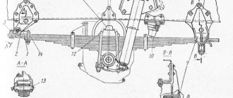
The pin bushings wear out quickly when operating the vehicle; do not forget to lubricate them. To check the kingpins, you need to lift the wheel with a jack using a mounting tool, rock the wheel and you will immediately see the result.
installation of shims
If the pin bushings are worn out on bumps when moving, a hammer effect is obtained and the seat of the pin in the beam begins to break and the beam will become unusable. It is also necessary to monitor the axial clearance.
checking the kingpin
We use a feeler gauge to check the gap between the beam and the steering knuckle; if the gap is 1.5 mm, then it is necessary to replace the thrust bearing or install shims.
Removing pads on KAMAZ
Any of the above reasons can lead to uneven wear on your brake pads. Replacing brake pads on KAMAZ requires their preliminary removal. Before removing it, you need to wait until the car cools down, place the car on a level surface, install a stop under its bottom, and special blockers under the wheels.
How to remove pads with a disc system
- The wheel nuts are unscrewed, the car is raised using a jack, and the wheel is removed.
- The brake fluid reservoir cap is unscrewed to simplify the process of pressing in the brake piston.
- The guides on the caliper are unscrewed. The brackets are removed for fixation with a screwdriver. If there is a pad wear indicator, it is necessary to disconnect the connector.
- Using a flat screwdriver, remove the pads to press in the brake piston (for this purpose, insert a flat, strong screwdriver into the gap separating the pads) and remove the brake pads.
How to remove pads for a drum system
- Removing KAMAZ from the handbrake.
- Unscrewing the bolts for fixation and removing the brake drum.
- Release the handbrake cable, remove all springs and rods on the rear brakes with a screwdriver, remove the pads.
Repair of the KAMAZ brake system
Content:
Common malfunctions of the KAMAZ brake system
The design features of the brake system of KamAZ vehicles have caused the appearance of malfunctions that are not typical for vehicles of other brands with a single-circuit brake drive.
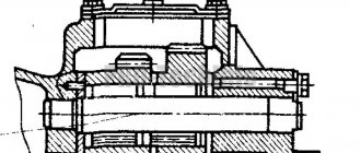
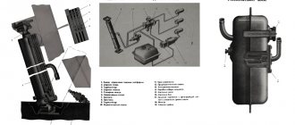
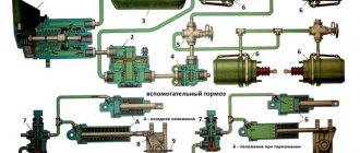
Rice. 1 a – brake chamber of front axle brakes type 24; 1 – boss; 3 – diaphragm; 4 – disk; 5 – spring; 6 – clamp; 7 – rod; 8 – body; 9 – flange; 10 – nut; 11 – protective cover; 12 – fork; 13 – bolt; 14 – compressed air supply; b – brake chamber of rear bogie brakes type 20; 1 – brake system housing; 2 – thrust bearing; 3 – sealing ring; 4 – pusher; 5 – piston; 6 – piston seal; 7 – energy accumulator cylinder; 8 – power spring; 9 – screw of the emergency brake release mechanism; 10 – thrust nut; 11 – cylinder pipe; 12 – drainage tube; 13 – thrust bearing; 14 – flange; 15 – brake chamber pipe; 16 – brake chamber diaphragm; 17 – support disk; 18 – rod; 19 – return spring.
The following malfunctions may occur in the brake system of a KamAZ vehicle:
- The pneumatic line air cylinders do not fill or fill slowly, and the pressure regulator often trips. The cause of the malfunction is leakage of compressed air due to damage to the housings of parts, the presence of dents and nicks on the end surfaces of the compressed air supply (discharge) bosses;
- Air cylinders of circuits III and IV are not filled. The cause of the malfunction is clogging of the supply pipes, deformation of the double safety valve body and malfunction of the double safety valve;
- The air cylinders of circuits I and II are not filled. The causes of the malfunction may be installation of the triple safety valve without clearance during installation, clogging of the triple safety valve, clogging of the supply pipelines;
- The air cylinders of the trailer (semi-trailer) are not filled due to a malfunction of the trailer brake control units located on the tractor or on the trailer (semi-trailer) itself;
- The pressure in the air cylinders of circuits I and II is higher or lower than normal when the pressure regulator is operating. The cause of the malfunction may be an incorrectly adjusted pressure regulator or a faulty two-pointer pressure gauge;
- Lack of vehicle braking using the service brake. The reasons for this may be an unadjusted brake valve drive, a faulty brake valve, incorrect installation of the brake force regulator drive, a faulty pressure limiting valve, an increased stroke of the brake chamber rods, exceeding the established value (40 mm);
- The parking and emergency brakes do not work. The reasons may be a faulty accelerator valve, a manually operated reverse brake valve, an emergency brake release valve, faulty spring energy accumulators, an increased stroke of the brake chambers rod, exceeding the established value of 40 mm;
- The vehicle does not release the brakes when the manually operated reverse valve handle is set to the “drive” position. The reason may be an air leak from the pipelines of the third circuit or from the atmospheric outlet of the accelerator valve, as well as a breakdown of the thrust bearing of the spring energy accumulator;
- When the vehicle moves, the rear bogie is braked. The reasons may be a malfunction of the two-section brake valve, incorrect regulation of the brake valve drive, or a failure of the seal in the energy accumulator;
- Lack of braking or ineffective braking of the trailer when the brake pedal is pressed or the manually operated reverse valve is turned on due to a malfunction of the single safety valve, trailer brake control valve, disconnect valves, connecting heads;
- There is no braking of the road train when the auxiliary brake is activated. This may occur due to malfunctions of the following devices: pneumatic auxiliary brake valve, damper mechanisms, auxiliary brake activation sensor, solenoid valve;
- The brake light bulb does not light up due to a burnt-out bulb, a malfunction of the brake light sensor or the pneumatic drive unit;
- Oil getting into the pneumatic system. The reason is wear of the piston rings and compressor cylinders;
- Slow filling of all brake system cylinders with air due to wear of piston rings and compressor cylinders and defects in pneumatic drive parts;
Repair of KAMAZ brake mechanism
During a major overhaul of the brake mechanism, the following are replaced with new ones:
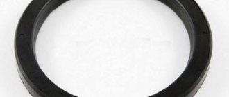
- rubber sealing rings of the expansion knuckle in the bracket; after replacing them, the sealing edges of the ring should not have any damage;
- metal-plastic bushings for the expanding fist, the pressing force of the bushings must be at least 6000 N; after replacement, the bushings are bored to a diameter of 38.0–38.027 mm;
- friction brake linings of brake pads.
New friction linings are riveted to the brake pads using a special press designed for riveting brake linings. The riveting of the linings to the block must be done in such a way that there is no gap between the linings and the block in the area of the rivets. Brake pads with linings assemblies are processed (ground) to the diameter of the bored brake drum on a machine. The radius of the pads with friction linings should be 199.6-200 mm.
After washing and cleaning, brake drums are subject to defects. When the working surface is worked out, more than 1 mm is bored on a machine for boring brake drums.
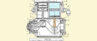
In the upper part of the machine bed 1 there is a spindle 7, the spindle is driven through a belt drive from an electric motor. A mandrel 6 is fixed in the spindle of the machine. Two cones 5 are installed on the mandrel, which are the base surfaces for the outer races of the wheel hub bearings. For boring, the drum is screwed with nuts to the hub. Together with the hub, the drum is installed on the conical mandrels of the machine. On the side of the frame there are guides for installing and moving the support 3. A tool holder 4 is fixed in the support for attaching the cutter.
The transverse movement of the caliper with the tool holder along the caliper guides is carried out by flywheel 2. The longitudinal movement of the caliper with the tool holder along the frame guides is carried out by handle 10. For boring the brake drums, cutters with carbide plates VK-3, VK-b are used. The drum rotates on the machine spindle. Cutting speed within 80-100 m/min.
!When boring brake drums, their internal diameter should not exceed 406 mm. For wheels of the same vehicle axle, the diameters of the brake drums must be the same.
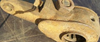
The expanding fist is subject to restoration if there are developments, corrosion, potholes, or dents up to 0.5 mm deep on its working profile. The difference in profile radii on the beam of the same name should not exceed 0.6 mm. Restoration of the working surface of the expanding fist is carried out by surfacing or plasma spraying followed by mechanical processing. The expansion knuckle splines should not show signs of wear.
Brake assembly
When assembling the brake mechanism, all rubbing surfaces of the parts (supporting surfaces of the expansion knuckle, roller, roller axes and pad support axes) are lubricated with a thin layer of Litol-24 lubricant. In addition, the expansion fist is additionally lubricated through a grease nipple located in the bracket. Contact of lubricant on the friction surface of the pads is not allowed. After assembling the brake mechanism, a brake drum is installed on the hub and the tightening of the wheel hub bearings is adjusted.
The final operation of repairing the brake mechanism is its complete adjustment. Full adjustment of the brake mechanisms of all wheels is carried out in the following sequence. After loosening the nut 4 securing the axles 1 of the brake pads (Fig. 2, a), the eccentrics are brought closer together, their axes are rotated so that the marks placed on the outer ends of the axles protruding under the nuts are one opposite the other. After this, the bolts securing the bracket of the expansion plate 3 are released.
Compressed air is supplied to the brake chamber at a pressure of 0.1-0.15 MPa and the output of the brake chamber rods is measured.
The size of the rod output is determined by the difference in measurements of its full output after air is supplied to the brake chamber and its position in the initial state. The difference in the results obtained should be 20-30 mm. If the stroke of the rod differs from the specified value, then it should be adjusted by rotating axis 1 (18) [Fig. 2, a (b)] of the worm of the adjusting lever 3 (14). a - location of the adjusting lever of the brake mechanism and the window in the brake disc for checking the gaps between the brake pads and the drum: 1 - worm axis with a tetrahedral head for rotating the worm when adjusting the stroke of the brake chamber rod; 2 - window for checking the gaps between the brake pads and the drum; 3 — lever of the expansion fist shaft; 4 - connecting axis; 5 — brake chamber rod fork; b - cross section of the brake mechanism: 1 - axis of the brake pad eccentric; 2 — brake disc, rigidly fixed to the bridge flange; 3 — shield; 4 - axle nut; 5 — pad axle lining; 6 — block axis pin; 7 — brake pad; 8 - spring; 9 — friction lining; 10, 21 — expansion knuckle bracket; 11 — roller axis; 12, 16 — expansion fist; 13 - roller; 14 — adjustment lever; 15 — expansion fist axis; 17 — brake pad (internal view); 18 — adjusting head of the worm shaft; 19 — worm shaft position lock; 20 — clamp spring; 22 - worm; 23 - plug; 24 — expansion knuckle shaft gear; 25 — splined tip of the expansion fist shaft
Replacing pads on KAMAZ Euro
Replacing brake pads on a KAMAZ all-terrain vehicle is possible using pads purchased in a store, or by independently restoring old ones. Most drivers do just that. Replacing KAMAZ rear pads involves removing the outdated friction substance from the spare parts, then cleaning the seating surface.
Before installation, the linings are ground using a lathe. The friction substance is installed on the brake pad, the holes are aligned. To ensure correct placement of the trim, all rivets are installed at the same time. Riveting starts from the central part to the edges. This increases the tightness of contact of the friction material to the surface.
How the kingpin works and how it works
The kingpin is a rod made of alloy steel. There is a flat on this rod into which the wedge is subsequently installed. The latter prevents a shift in the direction of the axis from occurring. The technical parameters of this part, required as part of replacing KamAZ kingpins, consist of diameter (45 mm) and length (232 mm). Installation of this element is carried out using a hydraulic press.
The functions of sliding bearings in the part we are describing are perfectly performed by bronze bushings. They are mounted in lugs located in the steering knuckle. Lubrication is carried out using a grease nipple and a hole in the bushing using grease.
The lugs at the bottom and top are covered with covers. They also prevent dirt from entering the unit. The lid located at the top has a safety valve. It helps remove excess lubricant. To relieve the assembly from axial forces, the lower eye includes a support roller bearing.
Why does the king pin turn sour?
So, you have already removed the wheel and hub and got to the king pin. Now the main thing is not to damage the steering knuckle itself. Why does this rod turn sour in the beam seat? There can be many reasons, but the main one is lack of lubrication.
The rotating mechanism has a cover with a plug, with which it must be periodically lubricated. The plug is unscrewed, a high-pressure syringe is connected and the pin is doused with nigrol. So, many people forget to do this procedure and the rod sticks to the beam. Another reason may be worn-out sealing elements (rubber rings) installed in special grooves on the rotating mechanism. In their absence, dirt gets under the axle and water gets in, causing it to rust and, accordingly, sour.
How to change
The pins are replaced when play appears in the steering knuckle. At the same time, the car’s wheels behave unstably, and while driving, knocking noises are heard in the front beam. This work can be done at a car service center, but most drivers replace the part themselves.
To dismantle it is necessary to raise the cabin to its extreme position, remove the wheel and caliper. After this, the steering knuckle covers are removed. You can replace the kingpins using a special tool and a 50-ton hydraulic jack, but most often a sledgehammer and attachments are used.
How to knock out
Before removing the kingpin, you need to knock out the locking wedge. It is located in the body of the fist eye. After unscrewing the retaining nut and using the attachment, they try to move it from its place with sharp blows of a sledgehammer. If this is successful, then the part continues to be knocked out. Otherwise, a hole with a diameter of 8 mm is drilled in the wedge approximately 2/3 of the way. After this, it is removed by hitting it with a sledgehammer.
It will be easier to knock out the kingpin if you heat the beam with a cutter. This operation must be carried out quickly so that the kingpin itself does not heat up. Some specialists use liquid nitrogen to cool the part - the effect is the same, but the likelihood of damaging the beam is reduced.