Adjusting the KAMAZ clutch: instructions
Reliability, excellent performance, efficiency - all this can be said about KAMAZ trucks.
The machines are in demand for household, commercial and military purposes. The key to long-term and trouble-free operation is constant checking of the technical condition. Adjusting the KAMAZ clutch is always relevant. This brand is usually equipped with a dry double-disc or single-disc clutch (friction type). During its entire service life, the unit experiences enormous loads. Competent selection of spare parts and timely maintenance will guarantee long-term operation. Adjusting the KAMAZ clutch basket requires experience and certain knowledge. Setting is necessary when:
- A crackling sound occurs when changing gears.
- Slipping at high speeds.
- Changing the free play of the clutch pedal (it has certain digital values).
If you ignore these signs, expect a serious accident!
Device
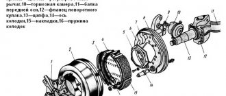
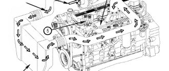
The KamAZ crankshaft design includes the following parts:
- Connecting rod and main journals, which are interconnected. Connecting rod type journals have a smaller diameter. They are used as support.
- Counterweight. Helps balance the weight of the piston and connecting rods.
- Knee. Equipped with one crankpin, which is located between two brushes.
- Sliding bearings. They allow the connecting rods in the journals and in the crankshaft mechanism to rotate.
- The shank on which the flywheel is mounted to take power from the crankshaft.
- Flange and brushes.
The difference between KamAZ crankshafts of different models lies in the material used (cast iron or steel), as well as in the number of connecting rod journals.
KAMAZ clutch adjustment technology
Removing and adjusting the KAMAZ clutch is carried out in several steps.
Adjusting the free travel of the KAMAZ clutch pedal
The pedal must have a play of 6 to 12 mm. Measurements are taken from the central part of the plate. The pedal must be lowered until the main cylinder starts working. If there is a deviation from the norm, adjust the distance between the PSU pusher and the stop at the top.
To do this, you will need an eccentric pin connecting the pedal to the top eye of the pushrod. The pedal for traction must press the clutch pedal against the stop from above. The finger is turned so that the gap between the piston and the PSU pusher is in the range from 6 to 12 millimeters. When finished, tighten the castle nut securely. The full pedal travel should be approximately 19 centimeters.
Adjusting the KAMAZ clutch
The manufacturer recommends maintaining a free play value in the range from 3.2 to 4 millimeters. To measure, you will need to move the fork shaft lever by hand. It must move in the direction from the spherical nut of the pusher. It is located on the pneumatic or hydraulic clutch drive amplifier. Adjusting the KAMAZ clutch clearance will require removing the spring: the lever should move no more than five millimeters. If the free play is less than three millimeters, then it is adjusted using a spherical nut. The idle speed of the clutch must be from 3.2 to 4 millimeters.
Adjusting the KAMAZ clutch drive
To measure the function indicator, it is worth pressing the pedal all the way. If the value is less than 24 mm, then complete shutdown will not occur. It is necessary to measure the free play of the pedal and the volume of fluid in the master cylinder. 380 cubic centimeters is the total volume in the hydraulic drive. If the data does not satisfy the requests, it is important to get rid of air in the system. This will return all indicators to normal.
Adjusting the KAMAZ clutch pressure plate
During this operation, you must strictly follow the sequence:
- Initially, the gearbox is dismantled. You can't do it without helpers.
- Remove the clutch basket.
- The clutch discs are dismantled: first the driven one, then the middle one, and finally the driving one.
- New parts are being installed. The order is already reversed.
- It is important to adjust the nickel of the KAMAZ clutch basket.
- The correct installation of all mechanisms is checked in detail.
- The gearbox returns to its place.
If there is only one disc in the clutch design, the job is much easier!
But even a KAMAZ single-plate clutch, adjusting its parts will require serious skills, strength and knowledge. Don't take risks - entrust the matter to professionals. Or do a one-time replacement with a real mechanic. For some mechanics, adjusting the KAMAZ double-disc clutch without removing the gearbox is a reality.
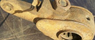
Adjusting the legs of the KAMAZ clutch basket
The case is carried out in several steps:
- The checkpoint is dismantled. Use wrenches to unscrew the fastening bolts.
- Raise the box: it is better to do this with a cargo winch.
- Check the condition of the coupling, tension spring element, and release bearing.
- Unscrew the screws connecting the pressure plate and flywheel. To dismantle the pressure element, the driven disk must be supported.
- Carry out troubleshooting of all parts of the system (preferably).
- Check the condition of the release bearing. A working mechanism rotates easily, without unnecessary sounds.
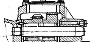
- Conduct a visual inspection of the working surface of the pressure plate feet. After installing the new parts, the KS feet are adjusted. In this case, you will need a flat slab.
The location of the paws is oriented towards the working position of the pressure plate surface. Important : the operation does not require removing the joint from the additional flywheel. In this work you will need wrenches for the adjusting screws. The KS feet must be positioned so that the distance from the working plane of the pressure plate to the upper edges of the spherical protrusions on the inner surface of the feet is no more than 41 millimeters. But 40 mm is better.
To check the installation of the paws, you will need a special plate. The spherical protrusions must touch the control plate (it is installed on the hub). After completing the adjustment, all screws securing the support plates are tightened until they stop. Assembly proceeds in reverse order.
Tightening diagram
First of all, it is important to remember that you need to pre-tighten the bolts in this order:
- the first two are installed above and below in the central holes;
- the third and fourth below, respectively, to the right and left of the middle one;
- the fifth and sixth at the top are also on both sides of the central one;
- the seventh and eighth go into the leftmost holes;
- the ninth and tenth to the right.
Next, you will need to tighten all the bolts in this order:
- the first stage - twisting is carried out to 2 kgf*m;
- on the second round, tightening is carried out according to the above algorithm, with the only difference being that the force is brought to 8 kgf*m;
- on the third pass, all bolts are turned exactly 90 degrees;
- The fourth stage fully corresponds to the previous one and is the final one.
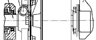
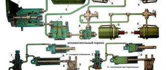
Design features of the clutch
The bulk of KamAZ trucks use a double-disc clutch with a radial arrangement of power springs. To operate the mechanism, a hydraulic drive with a pneumatic amplifier is used. Thanks to this design, the force required to press the clutch pedal is significantly reduced. During the operation of KamAZ, wear occurs on the clutch discs, which must be compensated for by adjustment. Correct adjustment of the mechanism ensures the fuel consumption declared by the factory and confident acceleration of an empty or loaded vehicle.
Installation of fuel equipment
Torque and procedure for tightening the head bolts in a VAZ-2109 car: video
Parts and assemblies of the high-pressure fuel pump, speed regulator, low-pressure fuel pump, hand pump and injector are thoroughly washed in summer diesel fuel, and the plunger pairs, injection valves and spray nozzles are thoroughly washed. in B-70 aviation gasoline. After washing, the parts are blown with dry compressed air. Wiping parts with cleaning materials is not allowed.
Damage to the metal braid of rubber hoses and dents more than 2 mm deep on steel pipelines are not allowed. Before assembly, low-pressure fuel lines are checked for leaks with air at a pressure of 0.3 MPa. Reducing the air pressure is not allowed. Before installation on the engine, the pipelines are washed with diesel fuel and blown with compressed air.
How is the adjustment carried out?
If problems occur with the clutch, you should try to make adjustments. When disc slippage occurs (sluggish acceleration, slight burning smell), it is necessary to set the correct clutch stroke.
If the disks are not fully spaced (difficult switching), you will have to perform more operations:
- Set the pedal stroke.
- Remove air from the drive lines.
- Check the liquid level in the PSU.
When using the Euro unit, only the pedal free play needs to be adjusted. Lubrication and adjustment of other clutch parts during operation of the machine is not provided, except for monitoring the height of the fluid level in the drive reservoir.
By adjusting the clutch on KamAZ 5320 and other models we mean setting the correct gap between the release plate plane and the lever heads, as well as adjusting the free play of the pedal and drive clutch. The permissible free play for the clutch pedal must be in the range from 6 to 12 mm.
The gap is understood as the distance between the points of the central part of the pedal platform when the pedal is released and at the moment the master cylinder begins to turn on. The free play is regulated by rotating the eccentric pin located in the connection of the pedal lever with the upper eye of the amplifier rod. The adjustment is made with the pedal tension spring fully depressed, i.e. the pedal should rest against the upper rubber buffer, which serves as a travel limiter.
For example, on KamAZ 65115 the do-it-yourself adjustment process is as follows:
- Unlock the pin castle nut pin.
- By rotating the finger you need to achieve acceptable free play.
- Tighten the nut and secure it with a cotter pin.
- Check the pedal's full travel. If everything is adjusted correctly, it should be between 185 and 195 mm.
On single-disc MFZ units, the adjustment is similar, but the pedal travel should be from 140 to 150 mm.
Below, the process of adjusting the free wheel is demonstrated using the example of KamAZ 4310, the author of the video is Vladimir Krasikov.
Clutch debugging
The next stage of adjustment will be to adjust the free play parameters of the clutch, the value of which should be from 3.2 to 4 mm. The measurement is carried out by rotating the adjusting nut.
The sequence of actions in this case:
- Loosen the fork mounting nut.
- Unscrew the fastening pin, allow it to move freely and remove it.
- Rotate the traction fork until the required clearance is obtained.
- Tighten the nut and install the pin in place.
- Install the locking pin.
- Check the setting. When the pedal is fully depressed, the clutch stroke should be at least 25 mm.
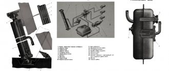
Debugging the full stroke of the amplifier pusher
Before starting to debug the mechanism, it is necessary to find out the stroke length of the pusher. To do this, you need to completely disengage the clutch and measure the stroke. If its value is 25 mm or less, then the clutch will not disengage completely. The driver will notice this problem immediately by the difficulty of shifting gears. To find the cause of the problem, you need to check the level of working fluid in the pusher cylinder. The standard volume is 380 cubic meters. see. If the level of the substance is insufficient, it should be topped up.
Hydraulic system diagram
Using the KamAZ 5511 model as an example, adding fluid is done as follows:
- You need to open the reservoir cap located on the drive housing.
- Add liquid to a level 15-20 mm below the edge of the neck.
The second reason for unsatisfactory operation of the amplifier may be air in the system. In this case, the drive system must be bled. This procedure is somewhat more complicated.
On KamAZ 55102 for this you need:
- Add fluid to normal level.
- Remove the protective cap from the bypass valve (installed on the CCGT housing), put on a rubber hose and lower it into a container with liquid.
- Sharply press the clutch pedal all the way.
- Open the valve one turn and press the pedal until the substance stops bubbling at the outlet of the hose. In this case, it is necessary to constantly add new fluid to the supply tank, not allowing it to fall below the 40 mm mark from the top of the tank.
- Close the valve, remove the hose and replace the cap.
- Add fluid to the operating level.
- To control the quality of work, you must press the pedal all the way - the pusher stroke should not be less than 25 mm.
Types and sizes of liners
In general, crankshaft liners are divided into two groups:
- The first type is called radical liners. They are located between the crankshaft and the places where it passes through the engine housing. They bear the greatest load, since it is on them that the crankshaft is attached and rotates.
- The second group includes connecting rod bearings. They are located between the connecting rods and the crankshaft and its journals. They also carry enormous loads.
Main and connecting rod bearings are manufactured individually for each engine type with their own dimensions. Moreover, for most automobile engines, in addition to the nominal, factory sizes, there are also repair inserts. The outer size of the repair liners remains unchanged, and the inner diameter is adjusted by increasing the thickness of the liner. There are four such sizes in total, with increments of 0.25 mm.
It is no secret that with high mileage of a car, not only the main and connecting rod bearings wear out, but also the crankshaft journals. These circumstances lead to the need to replace liners of nominal sizes with repair ones. To install one or another repair liner, the neck is bored to a certain diameter. Moreover, the diameter is selected individually for each size of the liner.
If, for example, a repair size of 0.25 mm has already been applied, then when getting rid of imperfections on the crankshaft journals, a size of 0.5 mm should be used, and in case of serious scuffing, 0.75 mm. If the bearings are replaced correctly, the engine should last for more than one thousand kilometers, unless, of course, the other systems of the car are in good working order.
There are also options when boring is not required and the liners are simply replaced with new ones. But people who do this professionally do not advise simply replacing the earbuds with new ones. This is explained by the fact that during the operation and operation of the liners, microdefects still appear on the shaft that are not visible at first glance. In general, without grinding there is a possibility of rapid wear and a short service life of the crankshaft.
Adjusting the KamAZ clutch basket
By adjusting the clutch basket we mean adjusting the tabs placed on the basket. This debugging can be done with the box removed or adjusted directly on the car.
When performing the task without removing the box, you will need a homemade tool, which is a 3.5 mm thick wire with a 20 mm long end bent at a right angle. Using such an improvised feeler gauge, check the gap between the release bearing and the support ring of the clutch feet. The gap is adjusted using a nut on the PSU rod. You can bring the paws to the ring through the hatch in the upper part of the clutch housing. At the same time, it is important to ensure that the paws fit as uniformly as possible to the surface. But it is more correct and reliable to adjust the clutch removed from the engine.
- Place the assembled pressure plate on the template, which will provide a gap of 29 mm.
- Loosen the mounting bolts.
- Set the position of the stop ring for the feet. All four paws should touch the ring at the same time.
- Check the runout of the working surface of the disk.
- Lubricate the front bearing located in the crankshaft.
- Install the clutch using a mandrel, which will ensure alignment of the mechanism discs and the engine shaft.
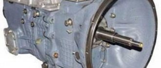
Technological process of engine assembly after major overhaul
Engine assembly at auto repair plants is carried out similarly to engine assembly at the Kama Association for the production of heavy-duty vehicles.
Parts for assembly are received as follows: basic parts (cylinder blocks, cylinder heads, crankshafts, camshafts) - from their restoration and testing stations; the remaining parts are from the assembly department. Parts arriving for assembly must be cleaned of dirt, varnish deposits, carbon deposits and scale, degreased, washed and dried. After cleaning, oil channels and holes in parts are washed under pressure and blown out with compressed air. They must comply with the drawings and requirements of the manufacturer's specifications.
Fasteners (bolts, studs, nuts) with worn or dented edges are not allowed for assembly. Thread damage of more than 2 threads is corrected with a thread-cutting tool.
Engines are assembled on a conveyor using the in-line method in the following sequence: after installing the cylinder block on the conveyor stand, plugs and seals are installed on its machines; the crankshaft is placed in the bed of the main bearings; bearings are covered with caps; the camshaft is inserted into the camshaft bushings; cylinder liners are placed in the sockets, and pistons assembled with rings, pins and connecting rods are placed in the sleeves; the lower heads of the connecting rods are put on the connecting rod journals of the crankshaft and closed with covers; rods and guides with pushers are mounted; The heads are placed on the upper part of the block, and its lower part, after installing the oil pump, is covered with a pan. Parts in the engine interfaces are assembled in accordance with the assembly drawings. Tolerances and fits of parts in mates must correspond to the data given in table. 31. After all connections, attachments are installed on the engine.
The cylinder block is installed on the conveyor stand using an overhead crane. At the stand, plugs, plugs, lower sealing rings of cylinder liners and upper sealing rings of cylinder liners are inserted onto the cylinder block without twisting or excessive stretching.
31. Tolerances and fits (clearances and interference) in mating parts of KamAZ-740 engines, mm
| Number and name of the associated part | Size | Gap (preference) in mating | ||
| according to working drawing | acceptable without repair | according to working drawing | after major renovation | |
| 740.1002011. Cylinder block - cylinder liner flange hole diameter | 145 | — | —0,74…—0,39 | —0,74…—0,39 |
| 740.1002021. Cylinder liner - outer diameter | 146 | — | — | — |
| 740.1002011. Cylinder block - diameter of the upper bore for the liner | 137,5 | 137 | — | — |
| 740.1002021. Cylinder liner - upper seat diameter | 137,5 | — | —0,01…—0,05 | —0,05…—0,07 |
| 740.1002011. Cylinder block - diameter of the lower bore for the liner | 134 | 134 | — | — |
| 740.1002021. Cylinder liner - bottom seat diameter | 134 | — | —0,01…—0,05 | —0,03…—0,07 |
| 740.1002011. Cylinder block - main bearing shell diameter | 100 | 100,03 | — | — |
| 740.1005170. Main bearing shells - shell thickness | 2,5 | — | +0,156…+0,096 | +0,165…+0,096 |
| 740.1005020. Crankshaft: | ||||
| journal diameter | 96-0,015 | 94,98 | +0,096…+0,156 | +0,096…+0,156 |
| crankpin diameter | 80-0,013 | — | +0,07…+0,117 | +0,07…+0,117 |
| 740.1002011. Cylinder block - crankshaft bearing cover seat width | 170 | 170,03 | — | — |
| 740.1005140. Crankshaft Bearing Cap - Cap Width | 170 | — | +0,001…+0,024 | +0,001…+0,024 |
Maintenance
In addition to settings, the clutch of KamAZ vehicles requires regular maintenance, since this significantly increases the service life and reliability of the mechanism on all KamAZ brands.
Using model 53215 as an example, maintenance consists of the following main points:
- Checking the tightness of the amplifier mounting bolts in the clutch drive circuit.
- Monitoring the tightness of hydraulic lines. There should be no oil stains on them.
- General check of serviceability of pedal assembly parts. All elements must be in good condition and not have large gaps in the connections.
- Checking the presence of lubricant in the clutch bearing and fork connection bushing. To supply oil in the clutch housing there are three points equipped with grease nipples. Oil is injected into them using a syringe.
- Draining condensate from the CCGT housing.
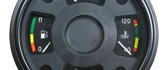
- Checking the fluid level in the amplifier reservoir.
When is clutch replacement required?
If all the work performed does not lead to the restoration of the clutch mechanism, then this becomes one of the signals to replace it.
Other signs of critical wear of structural elements are:
- sudden turning on of the disks, resulting in a hard jerk of the car;
- difficulty engaging all gears, accompanied by a characteristic crash;
- sluggish acceleration of the car, while the engine speed clearly does not correspond to the selected gear and speed;
- smell of burning pads when driving.
If such problems occur, it is necessary to stop moving as soon as possible and repair the mechanism. Continued operation of the vehicle with faulty or burnt-out clutch discs will lead to failure of the gearbox.
What are plain bearings
Tightening torque for cylinder head priora 16 valves: diagram and instructions for tightening bolts
To better understand why engine bearings need to be tightened to a certain torque, let's take a look at the functions and purpose of these elements. Let's start with the fact that these sliding bearings interact with one of the most important parts of any internal combustion engine - the crankshaft. In short, the reciprocating motion of the piston in the cylinder is converted into rotational motion precisely thanks to the connecting rods and crankshaft. As a result, torque appears, which is ultimately transmitted to the wheels of the car.
The crankshaft rotates constantly, has a complex shape, experiences significant loads and is an expensive part. To maximize the service life of the element, connecting rod and main bearings are used in the crankshaft design. Taking into account the fact that the crankshaft rotates, as well as a number of other features, conditions are created for this part that minimize wear.
In other words, the engineers abandoned the decision to install conventional ball or roller bearings in this case, replacing them with main and connecting rod bearings. Main bearings are used for the crankshaft journals. The connecting rod bearings are installed at the junction of the connecting rod with the crankshaft journal. Often, main and connecting rod bearings are made according to the same principle and differ only in the inner diameter.
For the manufacture of liners, softer materials are used compared to those from which the crankshaft itself is made. The liners are also additionally coated with an anti-friction layer. Lubricant (motor oil) is supplied under pressure to the place where the liner is connected to the crankshaft journal. The specified pressure is provided by the oil pump of the engine lubrication system
In this case, it is especially important that there is the required clearance between the crankshaft journal and the plain bearing. The quality of lubrication of the rubbing pair, as well as the engine oil pressure in the engine lubrication system, will depend on the size of the gap.
If the gap is increased, then the lubricant pressure decreases. As a result, rapid wear of the crankshaft journals occurs, and other loaded components in the internal combustion engine also suffer. In parallel with this, a knock appears in the engine.
We add that a low oil pressure indicator (in the absence of other reasons) is a sign that the crankshaft needs to be ground, and the engine liners themselves need to be changed taking into account the repair size. For repair liners, an increase in thickness of 0.25 mm is provided. As a rule, there are 4 repair sizes. This means that the diameter of the repair liner in the last size will be 1 mm higher. less compared to standard.
The plain bearings themselves consist of two halves, in which special locks are made for proper installation. The main task is to create a gap between the shaft journal and the liner, which is recommended by the engine manufacturer.
As a rule, a micrometer is used to measure the journal; the inner diameter of the connecting rod bearings is measured with a bore gauge after assembly on the connecting rod. You can also use control strips of paper for measurements, use copper foil or control plastic wire. The gap at the minimum mark for rubbing pairs should be 0.025 mm. An increase in the gap to 0.08 mm is a reason to bore the crankshaft to the next repair size
Note that in some cases the liners are simply replaced with new ones without boring the crankshaft journals. In other words, it is possible to get by only by replacing the liners and obtaining the desired gap without grinding
Please note that experienced specialists do not recommend this type of repair. The fact is that the service life of the parts at the mating point is greatly reduced, even taking into account that the gap in the rubbing pair corresponds to the norm
The reason is considered to be microdefects that still remain on the surface of the shaft journal if grinding is not performed.
How to adjust the clutch on a KamAZ
KamAZ is a very reliable vehicle that is used in many areas, mainly for cargo transportation. But, like any other equipment, even it can break down from time to time. The clutch system is subjected to especially heavy loads here. If you do not monitor its condition, it may fail. How to adjust the clutch on a KamAZ to improve the performance of the mechanism?
When to do repair work
Most KamAZ models are characterized by the installation of a double-disc clutch system. In rare cases, only one disk is used, but in modern modifications this option is no longer found. Type – friction, dry. This means that the system provides reliable adhesion to the motor, but at the same time, it is subject to enormous mechanical loads.
That is why the clutch on a KamAZ truck can fail at the most inopportune moment. The fact that certain problems arose with him can be understood by a number of factors. For example, the car will begin to noticeably slip, especially if the engine is running at high speeds. We may also be talking about the appearance of third-party sounds during gear shifting - noise, crackling, etc.
The fact that the clutch basket and drive on the domestic KamAZ need to be adjusted is also indicated by a violation of the pedal stroke. If the amplitude of its pressing does not correspond to the established standards, this will lead to the fact that the clutch disc will not be completely disconnected from the engine.
It is necessary to make adjustments if:
- at the beginning of the car’s movement, characteristic jerks occur;
- the pedal is either too loose or, on the contrary, too tight;
- the fluid level in the expansion tank has dropped;
- A fluid leak has been detected from the drive.
Stages of work
It is advisable to adjust the clutch basket in compliance with existing recommendations, strictly adhering to the order of work.
The first stage is adjusting the pedal
According to technical standards, the clutch pedal should move freely, without encountering resistance, by 6-12 millimeters. If this indicator has changed, then it needs to be restored. This work is performed by adjusting the gap between the pusher of the pneumatic hydraulic booster. To do this, you need to rotate the eccentric pin.
The second stage is debugging the coupling
Its stroke should be within 3.2-4 mm. The check is carried out as follows: the fork is moved to the side manually and the spring is removed. Next, using a spherical nut, the required range of motion of the coupling is set. You can also read about Ruchnik on KamAZ.
The third stage is adjusting the pusher stroke
If it is not enough, it means that the mechanism will not completely shut down, that is, the disk will not be disconnected from the motor. The normal stroke is approximately 25 mm. You can check it by first depressing the clutch pedal until it hits the bottom.
There are two ways to fix the existing problem:
- adding fluid - the corresponding marks on the cylinder tank indicate that it is not enough;
- bleeding - the method is to remove excess air from the system. You can pump it using a regular pump, hose, glass or plastic bottle.
If, after carrying out all the work described above, the problem with the clutch basket has not gone away, you will have to resort to a more complex measure - replacing this mechanism.
Choosing the right size
Sliding bearings consist of two halves, which have locks for fixing in place. There must be a gap between the shaft journals and the liners, which is recommended by the motor manufacturer.
When an engine repair is carried out without machining the crankshaft journals, you need to check the gap in the rubbing pair. The crankshaft journals are measured with a micrometer, and the inner diameter of the connecting rods is measured with a bore gauge.
More accurate measurements are taken with control strips made of copper foil or paper. In addition, sets of control plastic rods are available for sale.
The initially set gap for rubbing parts is from 0.025 millimeters, if the gap exceeds 0.08 millimeters, the shaft requires grinding to the next size, the liners are then taken accordingly to the size being machined too. If the gap is acceptable, a groove is not needed and liners are needed of the nominal size.
Work related to clutch replacement
It is recommended to replace the basket if the following shortcomings are found:
- even after adjustment, the car jerks and starts abruptly;
- extraneous sounds in the basket were and are still present;
- the car “thinks” for a long time and does not immediately start moving, despite the fact that the clutch was depressed according to all the rules;
- There is a characteristic burning smell in the cabin - this indicates that the clutch mechanism has simply burned out.
How to extend clutch life
Timely maintenance extends the life of the basket, an expensive and complex mechanism. First of all, you need to know how to properly adjust the clutch on a KamAZ. Check the pedal travel from time to time, because you don’t need to disassemble anything to do this. All accessible mechanisms and components must be lubricated.
Holding the pedal down for a long time to stop, for example, to slip, is categorically not recommended - this increases the load on the mechanisms and, accordingly, accelerates their wear.
Ignoring detected clutch problems is guaranteed to lead to deterioration in the functionality of the entire machine. The logical conclusion of such neglect will be the failure of the gearbox, the repair or replacement of which will cost a tidy sum. Failures of other KamAZ transmission mechanisms and components are also possible.
Problems when paying with bank cards
Sometimes difficulties may arise when paying with Visa/MasterCard bank cards. The most common of them:
- There is a restriction on the card for paying for online purchases
- A plastic card is not intended for making payments online.
- The plastic card is not activated for making payments online.
- There are not enough funds on the plastic card.
In order to solve these problems, you need to call or write to the technical support of the bank where you are served. Bank specialists will help you resolve them and make payments.
That's basically it. The entire process of paying for a book in PDF format on car repair on our website takes 1-2 minutes.
If you still have any questions, you can ask them using the feedback form, or write us an email at [email protected]