| ZIL-431510 | ||
| Load capacity, kg | 6000 | 6000 |
| Curb weight, kg | 4175 | 4550 |
| Including: | ||
| to the front axle | 2005 | 2140 |
| to the rear axle | 2170 | 2410 |
| Total weight, kg | 10400 | 10775 |
| Including: | ||
| to the front axle | 2510 | 2845 |
| to the rear axle | 7890 | 7930 |
| Gross trailer weight, kg | 80001 | 80001 |
| Max. vehicle speed, km/h | 90 | 90 |
| The same, road trains | 80 | 80 |
| Vehicle acceleration time to 60 km/h, s | 37 | 37 |
| Max. climbability by car, % | 31 | 31 |
| The same, by road train | 16 | 16 |
| Vehicle run-out from 50 km/h, m | 750 | 750 |
| Car braking distance from 50 km/h, m | 25 | 25 |
| The same, road trains | 26,5 | 26,5 |
| Control fuel consumption, l/100 km, vehicle: | ||
| at 60 km/h | 25,8 | 25,8 |
| at 80 km/h | 32,2 | 32,2 |
| The same, road trains: | ||
| at 60 km/h | 33 | 33 |
| at 80 km/h | 43 | 43 |
| Turning radius, m: | ||
| on the outer wheel | 8,3 | 9,5 |
| overall | 8,9 | 10,1 |
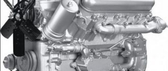
Engine.
Maud. ZIL-508.10, petrol, V-shape. (900), 8-cyl., 100×95 mm, 6.0 l, compression ratio 7.1, operating order 1-5-4-2-6-3-7-8, power 110 kW (150 hp) s.) at 3200 rpm, torque 402 N-m (41 kgf-m), fuel pump B10 - diaphragm, K-90 carburetor with forced idle economizer or K-96, K-88AT, K-88AM, air filter – inertial oil filter VM-16 or VM-21.
Transmission.
The clutch is single-disk, with peripheral pressure springs, the release drive is mechanical. Gearbox – 5-speed. with synchronizers in II, III, IV and V gears, gear. numbers: I-7.44; II-4.10; III-2.29; IV-1.47; V-1.00; ZX-7.09. Cardan transmission consists of two consecutive shafts with an intermediate support. Main gear – single hypoid, gear. number 6.33. A drive axle with a double bevel-cylindrical main gear can be installed. number 6.32.
Wheels and tires.
Wheels - disc, rim 7.0-20, fastening with 8 studs. Tires 9.00R20 (260R508) mod. I-N142B-1 or 0-40BM-1, Installation of tires mod. I-252B or VI-244. Air pressure, kgf/cm. sq.: ZIL-431410 – tires I-N142B-1 and O-40BM-1 – front – 4.0, rear – 6.3; tires I-252B and VI-244 – front – 3.0, rear – 5.8; ZIL-431510 – tires I-N142B-1 and O-40BM-1 – front – 4.5, rear – 5.3; tires I-252B and VI-244 – front – 3.5, rear – 5.8. The number of ears is 6+1.
Suspension.
The front is on two semi-elliptic springs with rear sliding ends and shock absorbers; the rear one is on two main and two additional semi-elliptic springs, the ends of the additional springs and the rear ends of the main ones are sliding.
Brakes.
The service brake system is with drum mechanisms (diameter 420 mm, width of the front linings 70, rear linings 140 mm, cam release) with a dual-circuit pneumatic drive, with a brake force regulator. Brake chambers: front – type 16, rear – type 24/24 with spring energy accumulators. Parking brake - on the brakes of the rear wheels from spring energy accumulators, drive - pneumatic. The spare brake system is combined with the parking one. The trailer brake drive is combined (two- and single-wire). Upon request, vehicles can be equipped with a brake drive without separation along the axles and with a single-line drive for trailer brakes (ZIL-130-80 car brakes). There is an alcohol fuse against condensate freezing.
Steering.
The steering mechanism is a screw with a ball nut on circulating balls and a piston-rack that engages with the toothed sector of the bipod shaft, the hydraulic booster is built-in, gear number 20, oil pressure in the booster is 65-75 kgf/cm. sq.
Electrical equipment.
Voltage 12 V, ac. battery 6ST-90EM, generator 32.3701 with voltage regulator 201.3702, starter ST230-K1, ignition distributor 46.3706 with centrifugal and vacuum regulators, ignition coil B114-B, transistor switch TK102-A, spark plugs A11. Some vehicles may be equipped with a contactless ignition system.
Filling volumes and recommended operating materials.
Fuel tank – 170 l, gasoline A-76; cooling system – 26l, water or antifreeze – A40, A65; engine lubrication system - 8.5 l, all-season up to minus 30°C oil M-6/10V (DV-ASZp-10V) and M-8V, at temperatures below minus 30°C - oil ASZp-6 (M-4/ 6B); power steering – 2.75 l, all-season oil grade P; gearbox - 5.1 l, all-season oil TSp-15K, substitute - oil TAP-15V, at temperatures below minus 30°C oil TSp-10; hypoid final drive housing – 10.5 l, all-season hypoid gear oil TSp-14 gi, at temperatures below minus 30°C oil TSz-9gip; two-stage final drive housing - 4.5 l, gearbox oil; shock absorbers – 2×0.41 l, liquid АЖ-12Т; windshield washer reservoir – 2.7 l, NIISS-4 liquid mixed with water; fuse against condensate freezing - 0.2 l, ethyl alcohol.
Weights of ZIL-431410 vehicle units
(in kg). Complete power unit – 640; engine – 500; gearbox (without parking brake) – 98; cooling system radiator – 20; cardan shaft – 36; rear axle assembly with brake mechanisms – 477; front axle assembly with brake mechanisms – 243; springs: front – 37; rear – 70; additional – 25; wheel with tire – 93; frame with buffer and towing device – 430; cabin – 280; tail (facing with wings and mudguards, hood) – 70; platform – 580.
Box ZIL-130 diagram
Moving the driven shaft gear forward engages first gear. 2nd gear is engaged by moving the synchronizer clutch back. If you move the synchronizer clutch forward, 3rd gear will engage. By moving synchronizer clutch 2 back, 4th gear is engaged. If you move the same synchronous clutch forward, 5th gear will engage. The intermediate shaft does not participate in the transmission of torque. Reverse gear is engaged by moving the 1st gear gear until it engages with the reverse gear unit.
A gearbox in which a change in torque is produced by changing the gear ratio. The most widespread are the stepped ones:
Gear shift diagram
gearboxes, where the gear ratio is changed by increasing or decreasing the gear ratio. Mechanisms that change the gear ratio continuously within certain limits are called continuously variable transmissions.
» The following types of continuously variable transmissions are used in cars: hydraulic (hydrodynamic and hydrostatic, otherwise called hydrostatic), mechanical (friction and pulse) and electric.
The most widely used continuously variable transmissions are hydrodynamic torque converters, which are usually installed in combination with stepped or planetary gearboxes. Such transmissions are called hydromechanical.
Step boxes are relatively simple in design and cheaper than continuously variable transmissions, but they have a limited number of gear ratios from three to five.
On off-road and heavy-duty vehicles, the number of gears increases due to the use of an additional gearbox. The higher the gear ratio of the gears in mesh, the greater the torque.
ZIL-130 gearbox diagram
Step-by-step transmissions have forced manual control, while planetary and continuously variable transmissions are mostly semi-automatic and automatic. The five-speed gearbox is shown in Fig. 131. Primary (drive) shaft 1 is connected to the engine crankshaft through the clutch. The secondary (driven) shaft is, as it were, a continuation of the primary shaft and is located on the same axis with it.
One end of the secondary shaft is mounted on a roller bearing 10 mounted at the end of the primary shaft, so the secondary shaft can rotate independently of the primary; the second end of the shaft is installed in a ball bearing 8.
Gears are mounted on the intermediate shaft 9. All of them, except for the first gear gear, are made separately and secured to it with keys. To reduce noise during operation and increase durability, the gears that are in constant mesh are helical.
A design feature of the ZIL-130 car gearbox is the presence of constant mesh gears on the secondary shaft. These gears, thanks to special treatment (phosphating) of the mating surfaces of the shaft and the gears of their lubrication grooves, are installed on the shaft without special bushings and bearings.
Checkpoint diagram
In a MAZ-500 type gearbox, the needle bearings of the secondary shaft gears, which are in constant mesh, are lubricated with oil ... under pressure. To do this, a gear oil pump is installed against the front end of the intermediate shaft on the outside of the gearbox housing, driven into rotation from the front end of the intermediate shaft.
shaft The gears are engaged by moving the gear along the splines of the shaft. But in this case, the impact of the teeth is inevitable, since the peripheral speeds of the gears are different. For easy and shock-free gear shifting, it is necessary that the peripheral speeds of the gears being engaged are the same.
The peripheral speed of a gear depends on the number of revolutions of the shaft on which it is mounted and on its diameter: the larger the diameter of the gear and the number of revolutions of the shaft, the greater its peripheral speed. To equalize the peripheral speeds of the gears before engaging them, a special synchronizer mechanism is used, which ensures their silent and shock-free engagement.
Cylinder block
The ZIL 130 cylinder block is cast from cast iron, with a load-bearing water jacket and insertable wet liners. To increase rigidity, the water jacket is divided by partitions into closed power circuits. The cylinder liners are cast from SCh18-36 cast iron with a ferrite content limited to 5%. An insert made of corrosion-resistant austenitic cast iron is pressed 50 mm into the upper part of the liner (this ensures a liner life of up to 200 thousand km). The thickness of the sleeve is 7.5 mm, the height of the sleeve is 188.5 mm. The camshaft is installed in the cylinder block.
SYNCHRONIZER
Synchronizers ensure silent operation when turned on. The difference in the rotation speed of the synchronizer clutch and the engagement of the gear is smoothly equalized due to the friction force that arises between them. The gearbox shift mechanism has a locking device that holds the shift rods in the required position.
Synchronizer ZIL-130
The synchronizer for LAZ-695, LAZ-697 buses and the ZIL-130 car (Fig. 132) works as follows.
When clutch 11 is moved to the left using the shift fork, the conical bronze ring will move with it and press against the conical surface of gear 1. The conical rings 7 and the clutch ]] are not connected rigidly to each other, but through three locking pins 5 with balls and a spring. Gear 1 and rings 7 rotate at different peripheral speeds. Until these speeds become equal due to the friction force, coupling 11 will shift (Fig. 132, b).
Synchronizer ZIL-130
Both bronze rings 7 are rigidly connected to each other using pins 12. The coupling 11 will move until the conical surface 10 of the coupling rests against the conical surface 9 of the pin (Fig. 132, a and d). When the speeds of the synchronizer rings 7 and the gear cone 1 are equalized, the pin 12 will be located in the center of the hole of the coupling 11, the blocking conical surfaces will separate (Fig. 132, c and d), and the coupling will continue its displacement. Its outer teeth 13 will engage with the inner teeth of the gear shaft 1, which will thus be connected via a synchronizer to the driven shaft 14.
Engine thermal conditions | Auto Club ZIL 130
When starting the engine in winter, it is necessary to carefully monitor the thermal operating conditions of the ZIL-130 engine. If the engine is cold, the thermostat valve will prevent coolant from entering the radiator until it warms up in the cylinder block jacket; During this period, there is a danger of freezing of the liquid in the radiator. However, it is not recommended to remove the thermostat from the engine cooling system under any vehicle operating conditions. It is impossible to pour cold liquid into a hot engine, as this can lead to the formation of cracks in the block jacket. You should periodically check the condition of the radiator plug valves, monitor the condition of all seals, preventing fluid leakage. It is prohibited to start or operate the engine for a short time after draining the coolant to remove its remainder from the system, as this can lead to destruction of the rubber sealing rings of the cylinder liners, loss of valve seats, burnout of the head gasket and warping of the head. In the summer, it is necessary to monitor the condition of the air channels of the radiator core of the cooling system and be sure to clean them if they are significantly clogged. The cooling system must be flushed for the first time after running the car (1000 km), and then twice a year - in spring and autumn. The engine and radiator must be flushed with water separately. First, flush the engine and then the radiator in the opposite direction to the water circulation in the engine. You need to remove the pipe together with the thermostat from the cylinder block, unscrew the drain valves from the block (one on each side of the block), and open the drain valve of the radiator pipe. Then water under strong pressure must be directed from the hose into the hole in the thermostat pipe. The system should be flushed until clean water flows from the drain valve openings. The drain taps must be cleaned and rinsed each separately, checked for serviceability and reinstalled. To flush the radiator (after running in the car, the radiator does not need to be flushed), water is directed under pressure into its lower pipe so that it pours out through the upper pipe (you must first put a hose on the pipe to drain the water), while the radiator cap must be closed. When the drained water becomes clear, you need to install hoses connecting the engine cylinder block to the radiator. The quality of the water used to cool the engine affects its performance and durability. If clean, soft water is used to cool the engine, the cooling system operates without failure until the engine is overhauled, and there is no need to remove scale. Scale has very poor thermal conductivity, so if there is even a slight layer of scale on the internal surfaces of the cooling system, heat removal sharply deteriorates. Scale is also dangerous because, when peeled off, it can clog the passages of the drain valves, interfering with drainage; in winter, this leads to freezing of the coolant in the block jacket and destruction of the cylinder block. If the water supply source is hard, then the water must be softened (remove calcium and magnesium salts) before filling it into the engine cooling system using one of the following methods. The first method is to boil water for 30-40 minutes. Boilers for boiling water can be of various designs. Some of the salts settle on the walls of the boiler, and some are collected in a sludge settler installed along the path of hot water. The second method is to add technical trilon to the water. Trilon is a white powder, non-toxic, easily soluble in water, and does not cause foaming when heated and boiled. Excessive amounts of Trilon do not have a harmful effect on the parts of the cooling system. The third method is chemical. This method of water softening requires special treatment plants. Soften water using sodium cation exchange filters. Such filters of various sizes and capacities are produced by industry. In case of scale deposits, as well as if a significant amount of corrosion products is detected in the water, the cooling system must be flushed as follows. Pour water, in 1 liter of which 20 g of technical trilon are previously dissolved. After one day of car operation (at least 6-7 hours), drain this solution and fill it with fresh one, change the solution within 4-5 days. After flushing is completed, fill the cooling system with water containing 2 g of Trilon in 1 liter.
The entry was published in the Engine, Maintenance section. Bookmark the permalink.
PTO power take-off.
Its name hints at the fact that it takes part of the engine torque and transfers it to special mechanisms. This could be a hydraulic pump or a utility equipment attachment. The PTO works in close conjunction with the gearbox, and is activated from the vehicle cabin. A huge amount of load and work falls on this small device.
Power take-off
Therefore, they always strive to make it strong and durable. There are 2 types of PTO, clutch dependent and clutch independent. The first one works when the engine is idling. Dependent PTO is lightweight, easy to install and requires almost no maintenance. They are mounted on a manual transmission and activated by the driver from the cab. An independent PTO can work with both manual and automatic transmissions.
It is installed on concrete mixers, road cleaning equipment, and agricultural machines. The place where the PTO is registered can be a gearbox, transfer case, engine, or the space between the engine and gearbox. KOM is a highly durable unit, but even it can break.
Box ZIL-130 diagram
Moving the driven shaft gear forward engages first gear. 2nd gear is engaged by moving the synchronizer clutch back. If you move the synchronizer clutch forward, 3rd gear will engage. By moving synchronizer clutch 2 back, 4th gear is engaged. If you move the same synchronous clutch forward, 5th gear will engage. The intermediate shaft does not participate in the transmission of torque. Reverse gear is engaged by moving the 1st gear gear until it engages with the reverse gear unit.
A gearbox in which a change in torque is produced by changing the gear ratio. The most widespread are the stepped ones:
Gear shift diagram
gearboxes, where the gear ratio is changed by increasing or decreasing the gear ratio. Mechanisms that change the gear ratio continuously within certain limits are called continuously variable transmissions.
» The following types of continuously variable transmissions are used in cars: hydraulic (hydrodynamic and hydrostatic, otherwise called hydrostatic), mechanical (friction and pulse) and electric.
The most widely used continuously variable transmissions are hydrodynamic torque converters, which are usually installed in combination with stepped or planetary gearboxes. Such transmissions are called hydromechanical.
Step boxes are relatively simple in design and cheaper than continuously variable transmissions, but they have a limited number of gear ratios from three to five.
On off-road and heavy-duty vehicles, the number of gears increases due to the use of an additional gearbox. The higher the gear ratio of the gears in mesh, the greater the torque.
ZIL-130 gearbox diagram
Step-by-step transmissions have forced manual control, while planetary and continuously variable transmissions are mostly semi-automatic and automatic. The five-speed gearbox is shown in Fig. 131. Primary (drive) shaft 1 is connected to the engine crankshaft through the clutch. The secondary (driven) shaft is, as it were, a continuation of the primary shaft and is located on the same axis with it.
One end of the secondary shaft is mounted on a roller bearing 10 mounted at the end of the primary shaft, so the secondary shaft can rotate independently of the primary; the second end of the shaft is installed in a ball bearing 8.
Gears are mounted on the intermediate shaft 9. All of them, except for the first gear gear, are made separately and secured to it with keys. To reduce noise during operation and increase durability, the gears that are in constant mesh are helical.
A design feature of the ZIL-130 car gearbox is the presence of constant mesh gears on the secondary shaft. These gears, thanks to special treatment (phosphating) of the mating surfaces of the shaft and the gears of their lubrication grooves, are installed on the shaft without special bushings and bearings.
Checkpoint diagram
In a MAZ-500 type gearbox, the needle bearings of the secondary shaft gears, which are in constant mesh, are lubricated with oil ... under pressure. To do this, a gear oil pump is installed against the front end of the intermediate shaft on the outside of the gearbox housing, driven into rotation from the front end of the intermediate shaft.
shaft The gears are engaged by moving the gear along the splines of the shaft. But in this case, the impact of the teeth is inevitable, since the peripheral speeds of the gears are different. For easy and shock-free gear shifting, it is necessary that the peripheral speeds of the gears being engaged are the same.
The peripheral speed of a gear depends on the number of revolutions of the shaft on which it is mounted and on its diameter: the larger the diameter of the gear and the number of revolutions of the shaft, the greater its peripheral speed. To equalize the peripheral speeds of the gears before engaging them, a special synchronizer mechanism is used, which ensures their silent and shock-free engagement.
Compressor ZIL 130. (Object 130) — DRIVE2
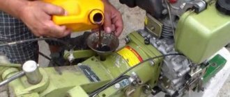
The recording of the toolkit talked about a compressor based on the ZIL 130, but there were no details. I got a little lucky and managed to buy a complete compressor, plus a spare pump and rings, as well as a KRP-6 spray gun for 4,500 rubles. Initially, the compressor had a gravity-fed lubrication system from a barrel, but for some reason the seller dismantled it. He argued that there were no gaskets leaking somewhere, plugged it, forgot! As I understand it, the compressor was not used after that. At home, having launched this miracle and blowing 6 kg/cm, bam and the front seal decided to escape! I took it apart, figured out what was what, and did a small upgrade by stirring up the lubricant barrel, but here’s the most interesting part! CAUTION: THE BARREL IS NOT FOR LUBRICATION! Details under the photo!
The compressor itself. If anyone wants to do everything, just look for a ZIL 130 pump, an electric motor, a belt, a VAZ brake barrel, hoses, fittings, a cylinder, I would recommend a propane one, but only a new one that has never seen GAS! Otherwise you will have GAGARIN! For reference, a propane cylinder has a working pressure of 16 kg/cm and a test pressure of 25 kg/cm.
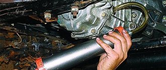
We take the brake cap and remove the rubber valve from it. We need a hole in the lid itself to allow gases to escape from the compressor.
Barrels from front-wheel drive. This one is better because it has two chambers and when gases escape, nothing splashes anywhere.
I turned the thread so I had to drill more and seal a new fitting.
General view of the assembly! And so this barrel is needed to collect gases and oil from the pump. Because excess pressure is generated in it during operation! I poured just a little oil into it, just up to the mounting plate. In the hope that it will sometimes flow to the bottom). Oil must be poured directly into the pump itself; I poured it up to the bottom of the bearing. The excess will rise into the barrel.
ATTENTION WHO WILL REPEAT THE DESIGN! If you have a pump without a crankcase, be sure to make a spacer plate on the bottom with a cutout in the center along the perimeter! Since the connecting rods will pass closely in the plane of the crankcase and the compressor will fail! If it’s not clear, ask in a private message!
I set up the unloading valve (from MAZ) and blew it out at almost 9 kg/cm.
SYNCHRONIZER
Synchronizers ensure silent operation when turned on. The difference in the rotation speed of the synchronizer clutch and the engagement of the gear is smoothly equalized due to the friction force that arises between them. The gearbox shift mechanism has a locking device that holds the shift rods in the required position.
Synchronizer ZIL-130
The synchronizer for LAZ-695, LAZ-697 buses and the ZIL-130 car (Fig. 132) works as follows.
When clutch 11 is moved to the left using the shift fork, the conical bronze ring will move with it and press against the conical surface of gear 1. The conical rings 7 and the clutch ]] are not connected rigidly to each other, but through three locking pins 5 with balls and a spring. Gear 1 and rings 7 rotate at different peripheral speeds. Until these speeds become equal due to the friction force, coupling 11 will shift (Fig. 132, b).
Synchronizer ZIL-130
Both bronze rings 7 are rigidly connected to each other using pins 12. The coupling 11 will move until the conical surface 10 of the coupling rests against the conical surface 9 of the pin (Fig. 132, a and d). When the speeds of the synchronizer rings 7 and the gear cone 1 are equalized, the pin 12 will be located in the center of the hole of the coupling 11, the blocking conical surfaces will separate (Fig. 132, c and d), and the coupling will continue its displacement. Its outer teeth 13 will engage with the inner teeth of the gear shaft 1, which will thus be connected via a synchronizer to the driven shaft 14.
PTO power take-off.
Its name hints at the fact that it takes part of the engine torque and transfers it to special mechanisms. This could be a hydraulic pump or a utility equipment attachment. The PTO works in close conjunction with the gearbox, and is activated from the vehicle cabin. A huge amount of load and work falls on this small device.
Power take-off
Therefore, they always strive to make it strong and durable. There are 2 types of PTO, clutch dependent and clutch independent. The first one works when the engine is idling. Dependent PTO is lightweight, easy to install and requires almost no maintenance. They are mounted on a manual transmission and activated by the driver from the cab. An independent PTO can work with both manual and automatic transmissions.
It is installed on concrete mixers, road cleaning equipment, and agricultural machines. The place where the PTO is registered can be a gearbox, transfer case, engine, or the space between the engine and gearbox. KOM is a highly durable unit, but even it can break.
Often, breakdowns are immediately visible; the PTO either stops turning on normally or begins to make loud noise. Problems are solved in different ways, starting with simply tightening the nuts and ending with complete disassembly of the PTO. In any case, without the appropriate knowledge and skills, independent repair of the PTO is not recommended by the manufacturer.
WATCH THE VIDEO
Gear diagram
Primary shaft
The input shaft is made of steel 25 KhGM, the depth of the nitrocarburized layer is 0.6...0.8 mm, the hardness of the surface layer is HRCe 61...66, the hardness of the core is HRCe 37...46.
Basic data on shaft seats, permissible wear of splines, journals and shaft seats for bearings, as well as data on gears.
Thickness of straight spline teeth - 5, 805…5, 855
The diameter of the roller bearing seat is 43.980…44.007
The diameter of the shaft journal for the ball bearing is 60.003…60.023
Shaft end journal diameter - 24.975...24.995
Secondary shaft
The secondary shaft is made of steel 25 KhGM, nitrocarburization depth 0.8...1.1 mm, surface layer hardness HRCe 61...66, core hardness HRCe 37...46.
The runout of the secondary shaft journals relative to the axis is allowed no more than 0.05 mm. The use of necks on crumbled cemented layers of a fatigue nature is not permitted.
Parameters of the secondary shaft journal splines
The diameter of the journal of the front end of the shaft for the roller bearing is 29.939..29.960
The diameter of the journal for the ball bearing is 50.003…50.020
The diameter of the journal for the bushing of the constant mesh gear of the fourth gear is 47.003...47.020
The diameter of the journal for the second gear constant mesh helical gear is 60.920…60.940
Thickness of the tooth of the splined part of the shaft for the synchronizer:
second and third gears - 8.88...8.94
fourth and fifth gears - 10.90...10.95
The tooth thickness of the splined part of the shaft for the first gear gear is 10.88…10.94
Tooth thickness of the splined part of the shaft for the flange - 5.99...5.94
Intermediate shaft
The intermediate shaft is made of steel 25KhGM, nitrocarburization depth is 0.8...1.1 mm, surface layer hardness HRCe 58...61, core hardness HRCe 35...45.
The runout of the intermediate shaft journals relative to the axis is allowed no more than 0.04 mm. Faulty shaft journals can be repaired by chrome plating and then machined to their nominal dimensions.
The weight of the ZIL-130 box is -98 kg
Dimensions of oil seals: 1 Primary shaft oil seal 42x62x10 2 Secondary shaft oil seal 58x8x16
Box oil ZIL-130 Tad-17 5.1 liters
WATCH THE VIDEO
What kind of oil to pour into the ZIL 130 engine. How many liters of oil in the ZIL bull engine?
Nowadays you can find a huge amount of goods. It can be divided not only by quality, but also by cost. It is worth noting that this also applies to the automotive market. And this is quite natural. After all, every manufacturer wants to make a huge profit from sales and invest less money. During the Soviet era, the ZIL 130 engine, which was distinguished by its good strength and durability, gained enormous popularity.
Many drivers said that this is simply an indestructible unit that does not require much attention. The first vehicle with the ZIL 130 engine was released at the beginning of 1962. This was the first truck to roll off the Moscow assembly line.
Description
The ZIL 130 engine was installed on all trucks, both ZIL 130 and ZIL 131. And this is not surprising. After all, if you look at the design, the ZIL 131 engine is very similar to the standard ZIL 130 engine.
These units had a small degree of unification. To put it simply, the power unit from the Zil 130 was slightly reduced in volume, to 6 liters, which made it possible to obtain lower fuel consumption. The power unit also received a two-chamber carburetor system and a special speed limiter.
The more powerful engine is the ZIL 375, which has a volume of about seven liters. This type of machine is mainly used at the Ural Automobile Plant. Thanks to this, it was possible to obtain an increased cylinder radius and piston stroke.
Specifications
The technical characteristics of the ZIL 130 engine deserve special attention.
| PARAMETER | MEANING |
| Model | ZIL 130 |
| Power unit type | Gasoline, four-stroke, carburetor |
| Power | 148 hp at 3000 rpm (with limiter) |
| Number of cylinders | 8 |
| How the cylinders are arranged | At an angle of 90 degrees |
| Minimum cylinder diameter and piston stroke | 100 mm diameter and 95 mm stroke |
| Total engine capacity | 6 liters |
| Compression ratio | About 6.5 |
| Minimum power at 3200 rpm | 150 horsepower or 110 kW |
| Torque at 2000 rpm | 401 Newtons per meter |
| Fuel consumption of the ZIL 130 engine | 313 grams |
| How cylinders work | 1 – 5 – 4 – 2 – 6 – 3 – 7 — 8 |
| Cylinder numbering: | Right 1 – 2 – 3 – 4 |
| Left 5 – 6 – 7 – 8 | |
| Total engine weight | 640 kilograms |
| Engine pusher ZIL 130 | Made of quality steel, has a slight overlay of cast iron, fully mechanical |
| Gas pipelines of the ZIL 130 engine | The intake is made of aluminum alloy, has a special cavity for heating the fuel mixture, and is located between the cylinder heads |
| The outlet is made of high-quality cast iron, located one on each side of the block | |
| Oil pump for ZIL 130 engine | Has several sections; gear, located on the right side of the cylinder block, the pressure reducing valve has a pressure of 320 kPa. In the lower section, oil is supplied to the oil cooler, the bypass valve has a pressure of 120 kPa. |
| Cleaning filters for the ZIL 130 engine | |
| Fine cleaning | Ceramic filter elements, equipped with economizer and pump |
| settling tank | Located on a bracket, has a slot type |
| Radiator | Has three rows, snake type |
The motor is installed on the following car models: ZIL 130, 131, 375 and 508.
I would also like to note that the ZIL 508 engine has three compression rings and one oil scraper ring. The thermostat of the ZIL 508 engine deserves special attention. It has a solid filling and is installed in the exhaust pipe. To the core
Answers (2)
I recommend filling the ZIL 130 manual transmission with universal mineral gear oil TAD-17 (TM-5-18), and TSp-15K and TSp-10 are also suitable.
The oil volume in the box is 5.1 liters; you need to fill it to the level until oil flows from the filler hole.
Interval - every 30,000 km or depending on operating conditions.
LUKOIL TM-5 85W-90 is a modern gear oil of medium viscosity. Semi-synthetic with an effective package of the latest additives. Specially created for use in manual transmissions of any type. It is highly resistant to wear, corrosion and oxidation processes. Has an extended working life. With the constant use of LUKOIL TM-5 85W-90 transmission oil, the degree of energy losses is reduced due to a decrease in the degree of friction between parts, and the smoothness of gear shifting improves. The oil guarantees reliable operation of a mechanical transmission under any operating conditions over a wide range of operating temperatures. With uv. Igor
1. FILLING CAPACITIES OF ZIL-130 CARS
Engine lubrication system with oil cooler. 8.5
Engine cooling system without heater and preheater. 26
Engine cooling system with heater and preheater. 29
2. BASIC DATA FOR ADJUSTMENT AND CONTROL OF ZIL-130 CARS
Clearance between valve stem and rocker arm for intake and exhaust valves on a cold engine, mm. 0.25—0.3
Gap between breaker contacts, mm. 0.3—0.4
Gap between spark plug electrodes, mm, . . 0.85—1
Oil pressure in the lubrication system of a warmed-up new
engine, kPa (kgf/cm2). 196—392 (2—4)
Minimum permissible oil pressure in the lubrication system, kPa (kgf/cm2):
at idle speed. 49 (0.5)
at a vehicle speed of 40 km/h in fifth gear. 98 (1)
Air pressure in the brake system, kGb (kgf/cm2) 588–755 (6–7.7)
Normal fluid temperature in the engine cooling system, °C. 80—95
Deflection of fan drive belts, power steering pump and generator under the influence of
force 40 N (kgf), mm. 8-14
Deflection of the compressor drive belt under the influence of
force 40 N (4 kgf), mm. 5-8
Free play of the brake pedal when installing a combination valve, mm. 40—60
Distance from brake pedal to floor at full
AutoNews / Reviews / Tests
How much oil is in a box of ZIL 130
How much oil is in a ZIL 130 box?
Keywords: ZIL-130 gearbox, ZIL-130 chassis
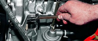
gearbox is attached to the clutch housing with 4 studs screwed into the clutch housing. Centering of the box is carried out along the flange of the cover 4 of the rear bearing of the drive shaft.
In the right wall of the crankcase there is a screw plug 57 for the control and filling hole, through which the box is filled with oil in the absence of a power take-off box.
In the left wall of the crankcase, at the bottom, there is a drain hole, closed by a screw plug 60, which is equipped with a magnet that attracts small particles of metal from the oil. On both sides of the crankcase there are two hatches with flanges for attaching the power take-off. It is allowed to take from the box a power of less than 22 kW (30 hp).
Rice. 40. Gearbox ZIL-130:
1 - drive shaft; 2, 21, 30, 45 and 53 - bearings: 3, 28, 31 and 47 - retaining rings; 4 — cover of the rear bearing of the drive shaft; 5 — synchronizer for fourth and fifth gears; 6 — fourth gear bushing; 7 and 40 - gear pair of fourth gear; 8 and 58 - gear pair of third gear; 9 — fork for shifting fourth and fifth gears; 10 — fork for shifting second and third gears; 11 — ZIL-130 gearbox cover; 12 — installation sleeve; 13 — retainer ball; 14 — clamp spring; 15 — gear shift rod lock pin; 16 — lock ball; 17 — synchronizer for second and third gears; 18 and 34 - second gear gear; 19 — fork for shifting first gear and reverse gear; 20 — first gear and reverse wheel; 22 — parking brake bracket; 23 — speedometer drive worm; 24 — parking brake drum; 25 — flange with reflector; 26 - nut; 27 and 51 — oil seals; 29 — intermediate shaft nut; 32 — gearbox housing; 33 - driven shaft; 35, 39 and 41 - support washers; 36 and 42 — locking rings; 37 — reverse gear of the intermediate shaft; 43 — intermediate shaft; 44 — intermediate shaft gear; 46 - plug; 48 — rubber ring; 49 — locking finger; 50 - roller bearing; 52 — locking plate; 54 — spacer sleeve; 55 - axis of the reverse gear block ; 56 — block of reverse gears; 57— threaded plug for the control and filler hole of the ZIL-130 gearbox; 58 — power take-off hatch cover; 59 — speedometer drive gear; 60 — drain plug with magnet; 61 — breather; 62 — fuse for engaging first gear and reverse gear; 63 — axis of the intermediate lever; 64 — spherical support body; 65 — gear shift lever clamp; 66 — lever support; 67 - spring; 68 — gear shift lever; 69 — intermediate lever; 70 — intermediate lever block; 71 — rod for shifting first gear and reverse gear; 72 — shift rod for fourth and fifth gears; 73 — shift rod for second and third gears; 74 - fitting for the speedometer flexible shaft.
Technical characteristics of gasoline engines of the ZIL-4331 dump truck
Quite often you can find the truck in question equipped with a gasoline engine. There are two modifications of gasoline engines for ZIL-4331:
- ZIL-508.10,
- ZIL-508.300.
The ZIL-508.10 power plant began to be produced much later than the 645th engine.
The new gasoline unit had more flexible operating characteristics. First of all, this was expressed by large angular rolls, which the installation was able to tolerate without consequences.
The performance parameters of the ZIL-508.10 were also more impressive:
- engine type
– V-shaped, overhead valve. The cylinders are located at an angle of 90 degrees to each other; - total number of cylinders
– 8, number of valves – 16; - total working volume of the combustion chamber
– 6 l; - maximum power at 3,200 rpm
– 150 hp. With.; - the total weight of the engine
with all additional equipment is 640 kg.
To date, production of this model has been discontinued.
The ZIL-508.300 engine is the lowest-power engine of all those installed on a truck of this type. It has the following performance characteristics:
- working volume of the combustion chamber
– 6 l; - maximum possible power at 3,200 rpm
– 135 hp. With.; - maximum torque
at 2,000 rpm – 377 N×m; - total number of cylinders
– 8 pcs.; - The cylinders are arranged in a V-shape
at an angle of 90 degrees relative to each other.
Fuel consumption when operating a car with gasoline engines is approximately 30-36 liters per 100 km at a speed of 90-95 km/h and may vary depending on the load.
If there is no cargo:
- at a speed of 60 km/h – 18 l;
- at a speed of 80 km/h – 23 liters.
If the ZIL-4331 moves as part of a road train, then the fuel consumption is slightly different:
- at a speed of 60 km/h – 25 l;
- at a speed of 80 km/h – 32 liters.
The maximum possible speed developed by a truck with a full load is 90-95 km/h.
ZIL-4331 can be equipped with engines of other modifications, but they are much less common.