| Transmission device modern car
|
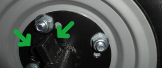
The differential is designed to distribute torque between the drive wheels and allows the wheels to rotate at different angular speeds. Differentials by design are divided into gear, cam and worm.
Gear differentials , based on the type of gears used, can be bevel and cylindrical. Based on the torque on the output shafts, differentials are divided into symmetrical (torque is equally distributed between the output shafts) and asymmetrical.
According to the torque distribution, the differential design can be:
• with constant distribution - conical and cylindrical; • with variable distribution - with forced locking and self-locking, as well as pulsating, freewheeling (overrunning) and increased friction.
When a car moves around a corner, its outer and inner wheels travel different paths. A wheel rolling along an inner curve travels a shorter distance than a wheel rolling along an outer curve. Therefore, the outer wheel of the car should rotate slightly faster than the inner one. This also happens when driving in a straight line if the rear wheels of the car have unequal diameters, which is observed when the load is unevenly distributed in the body, uneven tire wear, different internal air pressure in the tires, or when driving on an uneven road. So that the driving wheels of a car can rotate at different frequencies, they are mounted not on one common shaft, but on two so-called axle shafts, which are connected to each other by a special mechanism - a differential, supplying torque from the main gear to the axle shafts. If there are several drive axles, it becomes necessary to use a center differential .
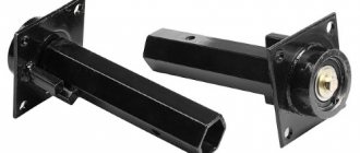
Center differential KAMAZ
|
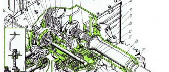
Gear and cam differentials are mainly used The gear differential is a planetary mechanism with two degrees of freedom.
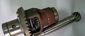
Cam limited slip differential.
Cam differential
A cam differential, unlike a bevel differential, has increased internal friction. This makes it possible to more rationally distribute traction forces between the drive wheels, which have different traction forces, and practically eliminate their separate slipping. In this case, the distribution of traction forces on the drive wheels is differentiated automatically, without driver participation, and is characterized by the blocking coefficient:
Kb = Mot/Mobg,
where Mot is the moment on the lagging shaft; Mobg – moment on the overtaking shaft.
Cam differentials can be made with horizontal or radial cams. The runners can be placed in one or two rows, performing the functions of satellites of conventional bevel differentials. When placing the crackers in a single row, the number of cams on the axle sprockets must be different so that at least one cracker transmits force.
When the crackers are placed in two rows, the number of cams on the sprockets is the same, but one row of crackers is offset relative to the other by half the pitch of the cams in order to eliminate pulsation of the transmitted torque.
A double-row cam differential is used on the GAZ-66-11 car (Fig. 1, a). It is mounted on two tapered bearings in the crankcase with the head of the gear and consists of a cup 4, a separator 2, an internal sprocket 1, an external sprocket 3, twenty-four cotters 5.
Separator 2 has two rows of holes in which crackers 5 are placed. The crackers are held by rings from falling out of the separator and turning around their axes. Separator 2, together with cup 4, is attached to the driven gear of the main gear and forms the differential housing. The outer sprocket 3 has six evenly spaced cams on the inner surface. It is installed freely inside the cup and is connected by splines to the axle shaft.
The inner sprocket 1 has two rows of six cams on the outer surface, arranged in a checkerboard pattern. This sprocket is located in the hole of the separator and is connected by splines to the second axle shaft.
In the working position, the differential parts are installed in such a way that the cracks come into contact with the cams of the outer and inner sprockets.
The differential works as follows (Fig. 1, b). When the car moves on a flat road, all the differential parts rotate around a common axis as one unit, while the angular speeds of the wheel shafts and the differential housing are equal to each other. The crackers do not move relative to the separator.
The torque is transmitted from the driven gear of the main gear to the separator 2, from it to the crackers 5, which press on the cams of the sprockets 1 and 3, causing them to rotate. The force of normal pressure of the crackers on the cams of the outer and inner sprockets is the same, but the circumferential forces P rotating the sprockets, due to different angles of inclination of the profiles of the cams on the sprockets, are different.
On the inner sprocket, which has a larger cam angle, the circumferential force is greater than on the outer one. A larger circumferential force applied at a smaller radius of the outer sprocket produces the same torque as a smaller circumferential force applied at a larger radius of the outer sprocket. Thus, the torque when driving straight on a hard road is distributed equally between the wheels.
When driving around a corner or on an uneven road, one of the wheels begins to rotate faster than the other. The sprocket connected to the lagging wheel rotates more slowly. With her cams, she pushes the crackers towards the second sprocket, accelerating its rotation, thereby the differential allows the wheels to rotate at different angular speeds.
When the crackers slide over the cams, friction forces Ptr arise on their surface. On a sprocket with a higher speed, the friction force is directed against rotation, slowing it down, and on a lagging sprocket - in the direction of rotation, thereby increasing the circumferential force, as a result of which the torque transmitted to the wheel increases three to four times.
The disadvantages of a cam differential compared to a bevel differential include:
- complexity of manufacturing;
- lower efficiency values due to increased friction between parts;
- increased wear due to high friction forces and contact stresses in parts.
***
Self-locking or automatic differentials
kat.ru
Design and malfunctions of the rear axle GAZ-53, GAZ-66
The structure of the rear axle of the GAZ-53A and GAZ-66 cars is shown in Fig. 1 and 2.
To increase durability, axles are equipped with a hypoid type main gear. The drive gear relative to the driven gear is shifted downwards by 32 mm
To prevent large deformations of the driven gear, the main gear is equipped with an adjustable stop.
The transmission and differential are mounted in a separate gearbox housing, which is loosely inserted into the hole in the axle housing and secured with bolts.
The rear axle gearboxes of the GAZ-53A and GAZ-66 vehicles differ only in the design of the differential.
On the GAZ-53A car, a conventional bevel differential with four satellites is used, and on the GAZ-66 car, to increase cross-country ability, a self-locking cam differential is installed, the design of which is shown in Fig. 63.
The separator 28 has 24 radial holes arranged in two rows in a checkerboard pattern, into which crackers 25 are installed.
Between the rows of holes for the crackers on the outer and inner surfaces of the separator, there are locking rings that prevent the crackers from turning around their axes, and also keep them from falling out of the cage when assembling the differential.
The outer sprocket 27 is freely installed in the hole of the cup 22, and the inner sprocket 30 is installed in the holes of the separator a and the outer sprocket.
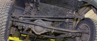
The rear axle housing of the GAZ-53A and GAZ-66 cars consists of two stamped halves, welded along the horizontal axis of the bridge.
This design ensures ease of installation and dismantling of the unit. The wheel axles at the ends of the crankcase of the GAZ-53 car are butt welded, and on the crankcase of the GAZ-66 car they are attached to the crankcase using studs.
Rear axle maintenance
Caring for the rear axle during operation consists of ensuring timely changes of lubricant, monitoring the lubricant level, checking the degree of tightening of the bolts securing the gearbox to the rear axle housing and the bolts securing the clutch of the drive shaft bearings, checking the tightening condition of the drive gear shaft bearings.
Cam differentials
Cam limited slip differential (axle differential in drive axles of the GAZ-66 car)
In the separator 6 (Fig. 6.18, a), made together with the differential housing cover, twenty-four crackers 4 are freely placed in two rows in the radial holes. The driven gear 5 of the main gear is attached to the cover. The ends of the crackers are in constant contact with the working surfaces of the cams of sprockets 1 and 2. To prevent the crackers from turning in the nests, they have flats on one side, and the separator has special rings. The working surfaces of the cams are built along circular arcs. The cams of the outer sprocket are made across the entire width of its inner surface, and the cams of the inner sprocket are arranged in two rows, offset in the rows by half a step.
A shift of half the pitch of the cams in the rows of the internal sprocket and the same shift in the rows of the crackers ensure the transfer of force from the crackers to the sprockets in any direction of rotation. If the crackers of one row are in a position in which the transmission of forces from the crackers to the sprockets is not possible, then the crackers of the other row will be in the working position and transmit force.
When the angular velocities of both driven sprockets are the same, i.e. ω1 = ω2, then the crackers do not move relative to the surfaces of the sprockets, i.e. ωв = ω1 = ω2. The separator, acting on each cracker in the working position, presses it against the surfaces of the cams of the outer and inner sprockets, from which torque is supplied to the drive wheels.
When the angular velocities of sprockets 1 and 2 are different, then the crackers, rotating together with the separator, move in its nests in the radial direction from the sprocket having a lower angular velocity (lagging) to the sprocket rotating at a higher speed (running). In this case, the working surfaces of the crackers slide relative to the surfaces of the cams. On the cams of a lagging sprocket, the sliding speed of the block is directed in the direction of rotation of the driving element, and on the cams of a leading sprocket, in the opposite direction. As a result, the angular speed of the lagging wheel decreases by the same amount as the angular speed of the ahead wheel increases.
The friction forces Ptr arising when the crackers slide on the surfaces of the cams (Fig. 6.18, b) increase the tangential component of the reaction on the lagging sprocket (Rot = P′ + Ptr cos α) and decrease on the leading one (Pzab = P′ – Ptr cos α). As a result, the moments are redistributed between the sprockets and shafts 3 and 7. The differential locking coefficient Kb = 3 – 5.
Rice. 6.18. Main gear of the GAZ-66 car:
a – design; b – diagram of the forces acting in the differential
Rice. 6.19. Double row cam differential:
1, 3 – differential housing cups; 2 – driven wheel of the main gear;
4, 5 – outer and inner sprockets; 6 – crackers
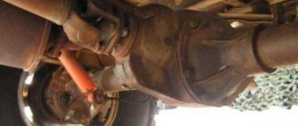
Half shafts
Axle shafts are used to transmit torque from the cross-axle differential to the driving wheels of the vehicle. In addition to torque, the following reactions act on the driving wheel of the car: vertical Z2 equal to the load on the wheel Gк; tangent X2 from the traction force or braking force and transverse Y2 equal to the lateral force that occurs when moving along a curved path and slope. All these reactions can create bending moments that are transmitted to the axle shaft.
Similar articles:
poznayka.org
Symmetric bevel differential design
• bodies (two cups - left and right); • satellite gears (two or four); • axis of satellite gears (crosspiece with axle spikes); • two semi-axial gears .
The torque from the body, which is the carrier of the planetary mechanism, is transmitted through the satellite gears freely rotating on their axes to the semi-axial gears, then through the axle shafts to the hubs of the drive wheels. The rotation speed of the axle shafts is disproportionately dependent on the angular speed of the differential housing. If such a differential is used as an inter-wheel differential, then when the car is moving, the angular speeds of the wheels will be determined by the ratio of the path traveled by the wheel and their rolling radius (in the absence of wheel slip). The only kinematic limitation: by how much one axle shaft overtakes the body, by how much the other lags behind it. Passenger car differentials typically have two satellite gears mounted on a common axle. In heavy-duty vehicle differentials, four satellite gears are installed, and their axles are combined.
Limited slip differential | Car device
How does a limited slip differential work?
The limited slip differential is installed on a GAZ-66 car (Fig. 133) and consists of two cups 1 and 7, supported by tapered roller bearings mounted in the drive axle housing. A separator 2 is rigidly attached to the left cup, in which two rows of radial holes are drilled, arranged in a checkerboard pattern of 12 in each row. Rusks 3 are installed in the holes, made of alloy steel, heat-treated and having high hardness. The crackers can move and come into contact with the inner (small) 5 and outer (large) 6 sprockets installed between cups 1 and 7. The crackers are kept from falling out and turning by retaining rings 4. The separator, together with the differential cup, is rigidly attached to the driven gear of the main gear, and the sprockets are connected with internal splines to the axle shafts 8. On the inner surface of the sprocket 6, six protrusions (cams) are evenly spaced, and on the outer surface of the inner sprocket 5 there are two rows of cams, staggered with six cams in each row. In the working position, the crackers come into contact with the cams of the outer and inner sprockets.
Fig. 133. Cam limited slip differential.
This is how a differential works. When the car is moving on a straight, level road, the wheel speed is the same, all parts of the differential rotate as one unit together with the driven gear of the main gear. The torque from the driven gear of the main transmission is transmitted to the separator, and from it through the cracks wedged between the cams to the sprockets and axle shafts. In this case, it is distributed equally between the wheels. On a turn or uneven road, when one of the wheels rotates faster than the other, the differential sprockets also rotate at different frequencies. The sprocket connected to the lagging wheel rotates more slowly and, as a result, with its cams it pushes the crackers towards the second sprocket, accelerating its rotation. At the same time, the crackers slide over the cams. Consequently, friction forces arise on the surfaces of the cams, the directions of which are different on the cams of the lagging and leading sprockets: on the lagging sprocket, the resultant of the friction forces is directed in the direction of rotation, and on the leading sprocket, in the direction opposite to the direction of rotation. Since friction forces create a moment relative to the axis of rotation of the sprockets, it is added up on the lagging sprocket, and subtracted from the torque on the advancing sprocket. Consequently, the moment transmitted to the lagging wheel turns out to be greater than the moment transmitted to the leading wheel. This has a positive effect on the vehicle's cross-country ability. For example, when one of the wheels slips, more torque is transmitted to the second, rotating at a lower speed, and the cross-country ability improves.
In a limited-slip differential, the locking coefficient, i.e., the ratio of the traction force of the non-slip wheel to the total force on the slip and non-slip wheels, is 0.8, while for a gear differential it is only 0.55. Consequently, limited-slip cam differentials create better conditions for the vehicle to pass through slippery road sections. At the same time, they are much more expensive than gear differentials, which hinders their production for mass implementation in cars.
***Test your knowledge and answer test questions on the topic “Drivetrain. Main bridge"
differential, sprocket, wheel, increased, cracker, friction
See also:
avtomobil-1.ru
All-wheel drive device
Cars designed for off-road driving and cross-country travel are equipped with a transfer case. The transfer case ensures equal distribution of forces between the truck's drive axles. It was thanks to the transfer case that the Shishiga gained almost legendary cross-country ability. The box consists of a housing with a crankcase. The crankcase is made of cast iron by welding. This is where the gear oil is located. On the cover there is a mechanism for turning on and off the front drive axle. The drive shaft in the GAZ-66 gearbox is connected to the secondary shaft of the gearbox. It received splines on which a gear-carriage is also installed, providing connection to the rear axle and downshift. There is also a rear axle shaft that meshes with the carriage gear. Torque is transmitted to the front shaft via an intermediate shaft. The transfer case operates in several modes: only the rear axle is connected, both axles are connected with interaxle locking.
Both GAZ-66 axles are driven, the front one can be switched off. Hypoid axles with a gearbox on the axle. The gearbox is protected by a metal casing along with the cardan shaft cross. In order to improve off-road performance, the manufacturer introduced self-locking cam differentials into the car. The differentials are engaged if there is a large difference in wheel speed. One of the possible conditions is wheel hanging or slipping. Self-locking differentials were installed based on the purpose of the vehicle: in the army, driving culture is not always at a high level. The GAZ-66 suspension is the same for both axles: on longitudinal semi-elliptical springs, reinforced with telescopic hydraulic shock absorbers with a long stroke.
Limited slip differential - Encyclopedia of Mechanical Engineering XXL
Rns, 170. Cam-type limited slip differential for the GAZ-66 car [p.237]
Fig. 171. Limited slip differential for cars [p.238]
The limited slip differential (cam) is installed between the wheels of the drive axles of the GAZ-66 car. In separator 6 (Fig. 117, a), made together with the differential housing cover, in [p.179]
The limited slip differential (cam) is installed between the wheels of the drive axles of the GAZ-66 car. In the separator 6 (Fig. 126, a), made together with the differential housing cover, twenty-four crackers 4 are freely placed in two rows in the radial holes. The main gear wheel 5 is attached to the cover. The ends of the crackers are in constant contact with the working surfaces of the cams of sprockets 1 and 2. To prevent the crackers from turning in the nests, they have flats on one side, and the separator has special rings. The working surfaces of the cams are built along circular arcs. The cams of the outer sprocket are made along the entire width of its inner surface. The cams of the internal sprocket are arranged in two rows with a half step offset in the rows. [p.162]
| Rice. 146. Limited slip differential for MAZ vehicles |
The self-locking limited slip differential (cam) used on the GAZ-66 car is shown in Fig.
16.21, a, b. It consists of an inner 5 and outer 6 sprockets, between the cams of which the cracks 3 of the separator 4 are placed. The separator is made integral with the left differential cup and is connected to the driven gear of the main gear. The right cup (not shown in the drawing) freely covers the outer sprocket and, together with the left cup, forms the differential housing. The differential sprockets with their internal splines are connected to axle shafts 1. [p.203] The diagram of the limited slip differential used on MAZ vehicles is shown in Fig. H.Z. [p.259]
Fig, x.4. Cam type limited slip differential [p.261] In Fig. 104 shows the details of the cam limited slip differential installed on GAZ-66 vehicles. [p.195]
The cam limited slip differential installed on GAZ-66 vehicles is shown in Fig. And 1.6, A cracker is loosely inserted into the radial slots of the drive cage 10 connected to the driven gear 13 of the main gear. Clips 11 and 12 have cams (protrusions) and are connected to the axle shafts. The rotation from the cage /O is transmitted through the cracks 9 and the cams of the cages // and 12 on the axle shaft. The axle shafts can rotate at different frequencies due to the radial movement of the nuts 9 along the cams of the races 11 and 12. However, due to the increased friction between the nuts and the races, turning the axle shafts requires a significant difference in the value of the resistance on the wheels. As a result, a torque sufficient to move the car is transmitted to both axle shafts, and when one of the wheels slips, a complete stop of the other wheel, which experiences greater road resistance, occurs less frequently. [p.181]
The limited slip differential of the K-700 and K-701 tractors is made of spur gears. The main parts of the differential are the housing, two driven coupling halves 2 (Fig. 5.36, a) and 4, ring 9 of the drive coupling 10, two split gear rings 8, 11 and two hubs [p.287]
The cam limited slip differential of the GAZ-66 car consists of a separator 1 (Fig. 5.36, b) with two rows of holes arranged in a checkerboard pattern. 24 crackers are inserted into the holes 2. [p.287]
The front axle consists of a main single-stage bevel gear, including drive 13 (Fig. 5.47) and driven 14 gears, a self-locking limited slip differential and wheel gearboxes. [p.302]
The self-locking limited slip differential consists of two housings 15 and 19, which house four satellites 25 on two axles 16, [p.302]
Front drive axle (Fig. 16.1). It consists of the following main mechanisms: center gear, limited slip differential and two-stage final drives. [p.197]
Types of differentials. There are mainly three types of differentials used: gear, cam and worm. The differential can be simple or self-locking (limited slip differential or freewheel). Gear differentials are classified as simple, while cam and worm differentials are classified as limited slip differentials. [p.231]
Limited slip differential. The GAZ-66 car is equipped with a cam limited slip differential. Separator 1 (Fig. 148) has two rows of holes into which 24 crackers are freely inserted in a checkerboard pattern. On the outer and inner surfaces of the separator, between the rows of holes for the crackers, there are locking rings that prevent the crackers from turning and keep them from falling out of the separator during assembly. The inner tops of the crackers rest against the inner sprocket 4, seated on the splines of the left axle shaft, and the outer ends of the crackers rest against the outer sprocket 5, seated on the splines of the right axle shaft. Outer sprocket 3 has [p.235]
Cam limited slip differential for GAZ 66 [p.235]
Cam limited slip differential. On GAZ-66 cars a cam limited slip differential is installed. The separator of the driving axle shaft 1 (Fig. 176) has two rows of holes into which 24 crackers 2 are loosely inserted in a checkerboard pattern. The inner tops of the crackers abut against the cage 4, seated on the splines of the left axle shaft, and the outer ends of the crackers - into the cage 3, sitting on splines of the right axle shaft. The outer race 3 has six cams evenly spaced along the inner circumference, and the inner race 4 has two rows of cams arranged in a checkerboard pattern. Thus, the leading separator is connected by breadcrumbs 2 to the cages 5 and 4 and rotates with them. If the angular velocity of both axle shafts is the same, then the crackers 2 are stationary and the separator 1 with cages 3 to 4 rotates as one. The axle shafts can rotate at different angular velocities due to the movement of the dry [p.225]
| Rice. 175. Cam limited slip differential of the GAZ-66 car |
The limited slip differential of MAZ vehicles is shown on the RNS. 176. It differs from a conventional bevel differential in that its satellites are pressed against the liners 3 through the support washers 6 by the force created by the springs 1. Since the liners 3 are relatively motionless [p.227]
| Rice. 3.2.37. Limited slip differential designed by CF, serially installed by Opel ia mod. Admiral and Diplomat |
| Rice. 3.2.38. Section AA (see Fig. 3.2.27) of a limited-slip differential designed by CF. The mutually perpendicular bevels made at their ends, crossing in the middle part of the satellite axis, and the satellites in section are clearly visible |
If there is a simple differential in the drive axle, approximately the same torque is supplied to the wheels.
Therefore, this statement is true when installing a limited slip differential and when applying a torque to the wheels that exceeds the torque determined by the adhesion of the wheels to the road. — Approx. ed. [p.334] One of the limited slip differentials that has received practical application on cars is the cam differential (Fig. 94). The rotation of disk 3, connected to the driven gear of the main transmission, is transmitted through the cracks 4 and cams at the ends of the flanges 2 and 5 on the axle shafts 1 and 6. If, due to road resistance, one of the flanges 2 or 5) lags behind, and the other rotates faster, then the friction forces on the side of the crackers on the lagging flange they are directed along the rotation, and on the leading flange they are directed against the rotation. As a result, on-164 [p.164]
A cam universal joint of equal angular velocities is used in the front wheel drive of the Ural-375 car (Fig. 16.16, c). The design of the hinge includes an outer axle shaft 8 of the wheel, which enters with the splined end into the fork 9 of the hinge. The inner axle shaft is made as one piece with the fork 9 of the hinge, and its outer end is connected to the differential gear with a splined joint. In the forks 9, fists 10 are installed, in the grooves of which a steel disk I is placed. When the hinge operates, the axle shafts rotate together with the forks around the fists in the horizontal plane, and together with the fists around the disk in the vertical plane. This ensures the transmission of torque to the driven and steered front wheels. The disadvantage of the joint considered is the increased friction in the places where the disc and cams meet the forks, as a result of which the efficiency decreases and the heating and wear of the joint increases during operation. [p.198]
The value of the blocking coefficient is for a differential with low internal friction = 0.1-g-0.2 with increased friction = 0.2-0.6 for a locked one to 0.6 (for more details, see Chapter X, 46). [p.69]
Rotation from a differential box consisting of cups Fig. 72, Diagram of forces and moments, actions 1 and 5, are transmitted through the dryers to the drive wheel of the car pi 2 and the cams of the races 3 and 4 to 3, the axle shafts. The axle shafts can rotate at different speeds due to the radial movement of the nuts 2 along the cams of the races 3 and 4. However, due to the increased friction between the nuts and the races, a significant difference in the resistance value on the wheels is required to rotate the axle shafts. As a result, a torque sufficient to move the vehicle is transmitted to both axle shafts, and when one of the wheels slips, the other wheel stops completely, Fig. 73, Axle shafts experiencing greater co- a - completely unloaded b - semi-resistance of the road, occurs less frequently. [p.129]
The gear differential can be made with bevel, spur or worm gears. The last case corresponds to a limited slip differential with the indicated disadvantages. [p.47]
The differential design is conical, high friction, self-locking. [p.197]
Application of EMO. In connection with the increase in performance properties, it is advisable to use electromechanical processing for a wide range of parts operating under various conditions of friction and wear. Thus, the use of EMP is effective for parts of transport, agricultural, road, and construction machinery, which during operation are subject to heavy loads under conditions of boundary friction and abrasive wear. An example is the strengthening of the journals of locomotive spring suspensions, journals of large-sized shafts, king pins, ball joints, camshaft cams, differential cups of the rear axle of a car, fillets of gearbox shafts, engine cylinders, pump cylinders, hydraulic and pneumatic mechanisms, end surfaces of piston rings, discs braking devices. [p.562]
Note that the increased friction moment in the differential, which helps improve the vehicle's cross-country ability, increases the load on the transmission, since this moment always acts when the vehicle turns, regardless of the need to increase torque in these conditions. Therefore, the choice of friction moment is approached based not only on the off-road conditions, but also on the vehicle’s handling and the reliability of the transmission. Typically, the differential locking (friction torque) is selected so that the torque ratio on the car wheels is 2.5...3.5. [p.103]
The limited slip differential (Fig. 171) works like a regular bevel differential. But since the average diameter of the support washers 6 is significantly increased and springs 1 are installed, which constantly press the satellites 5 to the liners 3, stationary relative to the differential housing, then on the support surface [p.238]
It is advisable to dwell at least briefly on assessing the effectiveness of blocking cross-axle differentials from the point of view of vehicle cross-country ability. If a conventional cross-axle differential is blocked or a limited-slip differential is used, the vehicle's traction force on a non-uniform supporting surface increases. However, the increase in traction force is not the same for different types of vehicles. [p.204]
The GAZ-51 car has a single main gear consisting of a pair of bevel gears with spiral teeth. The drive gear rotates on two bevel and one cylindrical bearings. A spacer and shims are installed between the tapered bearings to adjust the bearing preload. The driven gear is rigidly connected to the differential box cup. The differential structure is similar to that described above. The GAZ-66 car is equipped with single main gears with a pair of bevel gears and a cam limited-slip differential. [p.183]
The limited slip differential (Fig. 146) works like a regular bevel differential. But since the average diameter of the support washers 6 is significantly increased and springs / are installed, which constantly press the satellites 5 against the liners 3, which are stationary relative to the differential housing, then increased friction occurs on the surface of the support washer 6, making it difficult to freely rotate one axle shaft relative to [p. 228]
Differentials in design are very diverse. Bevel and cylindrical differentials are the most common in transmissions of all-wheel drive vehicles. The disadvantage of differentials is that they allow the implementation of a torque approximately equal to twice the minimum (at any wheel) torque. To eliminate this drawback, they provide either forced blocking of the differential or an increase in friction in it. For center differentials, forced locking is mandatory, for cross-axle differentials - depending on the purpose of the vehicle. Limited slip differentials are used only as cross-axle differentials. [p.103]
The friction in a simple differential is small, as a result of which the total traction force increases by only 4-6%. In worm and cam differentials, which are installed on off-road and off-road vehicles, the friction is much greater, and therefore the total traction force increases by 10-15%. Limited slip differentials are also often used. The design of one of these differentials is shown in Fig. 107. It is equipped with two friction clutches, disks 9 of which are connected to the side gears of the differential, and disks 10 are connected to its housing 1. [p.240]
The main gears are one- or two-stage (see Fig. 43) with symmetrical bevel differentials, usually consisting of four satellites. To prevent slipping of the wheel(s) on one side of the car and loss of traction, the differentials are blocked by the simplest blocking - a rigid connection of one of the axle shafts to the differential cup. The locking drive can be mechanical, pneumatic, hydraulic or electromagnetic. Limited slip differentials are known that transfer up to 20% of the power to a non-slip wheel. Some machines, such as motor graders, do not have a differential, which is due to the large chassis of the machine. [p.99]
mash-xxl.info
How does the differential work on gas 66
What if you put differentials from Gas 66 in Zil 131 axles, is this possible??? | Topic author: Wataru
who thinks about this???
Denis (Simrin) Most likely not. Otherwise, someone would have installed it a long time ago. On the 157th, if you get confused, you can probably stick it in. It comes with gearboxes from the 51st lawn. And on the 131m, if you constantly drive through shit without going onto the asphalt, then it’s probably easier to weld the differential. Rear and middle. Well, or a more difficult option, find a cart from 4334, there is a forced one.
Konstantin (Akrura) Well then it’s definitely easier to find bridges from 4334.
By the way, I didn’t know that 4334 had bridges with locks, I thought the same as the 131st. Where is the information about blocking 4334??
Denis (Simrin) I’m not sure about the simpler one. This is a rather rare car. We have one in the forestry enterprise, but it already has bridges from the 131st. The driver did not know how to use the locks and broke it. And we have a hard time with spare parts for such bridges. Therefore, from They installed the 131st. I don’t know where to get the information, it’s best to find the Operating Instructions for such a ZIL, and I’ve only seen on the Internet that they indicate in the specifications that there is a blocking of the rear and middle axles. But I haven’t seen any drawings or even photographs of these bridges. So I think it won’t be easy to smarten up the blocking on 131st, my brother has 3 of them, and we were also thinking about how to do it. But without bridges 4334, nothing will work out.
Konstantin (Akrura) Yes, the car is really rare, even on the Internet there is very little information about it! But the 131st needs blockages like air, otherwise it gets up out of the blue in winter! What if we also look at the differentials of Kamaz and Ural? Listen, maybe someone just hasn’t thought about installing locking differentials from other cars in their original axles.
I just haven’t come across such topics, all that was close to this was the installation of bridges from the 66th to the 131st.
Denis (Simrin) Blocking is a good thing, of course, but I think installing an ICD on the 131st will be commensurate with the cost of the car itself. So it’s probably better to forget about it, for example, I have no problems with this on the 131st in winter. Knowing that there are no blockages, you have to try the ability to prevent a strong redistribution of the load between the wheels of different sides, and everything will be fine. Although I would also like to install a blocker. There is one office in Chelyabinsk they make self-blocks for the Urals and Kamaz, if you order them, I think they will make them for the 131st, but it will be expensive. .To. single order. Here is a little about 4334 https://www.os1.ru/article/firm/1998_04_A_2005_10_20-1..
Boris (Marissa) Moreover, 4334 bridges with forced locking are much better!
Denis (Simrin) If only I could find where they are. A rare thing.
Vyacheslav (Michayahu) Why wasn’t the ICD initially included in 131? Doesn't any serial modification have an ICD?
Danil (Diethild) Denis, Please tell me the name of the office we have (in Chelyabinsk) that deals with blocking URAL 4320 bridges. I would be grateful!
Denis (Simrin) Danil, https://www.dak4x4.com/
Danil (Diethild) Denis, thank you very much!
Tags: How does the differential work on gas 66