An overhead crane is a crane with a load-handling mechanism, suspended from a hoist or trolley, which moves along a movable steel structure or bridge.
There are taps:
- with grab and grips for containers (special);
- with hook (general value);
- metallurgical;
- with magnet.
The design of electric grab cranes is similar to that of hooks. The only difference is the trolley: it has two lifting mechanisms: the first is for grab ropes, the second is for lifting ropes.
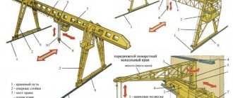
A grab crane consists of a bridge [2], a cabin [1] and has a special trolley [3], to which a grab [4] is suspended on steel ropes. The lifting capacity of cranes varies from 5 to 10 tons. Accordingly, the capacity of the grabs is from 1.6 to 10 cubic meters. The spans of overhead cranes are measured in meters: from 10 to 34.5 meters. The lifting height is 24 meters.
In cases where it is necessary to move or reload bulk, lump or bulk cargo, overhead grab cranes or loader cranes are used. They differ from other cranes in that they are equipped with a special grab.
Main design elements
- Supports or crane tracks
along which the main mechanism moves. - The main beam
rests on supports and moves along them on special wheels in one direction. - A trolley mounted on a beam
moves in a direction perpendicular to the movement of the main beam. - Electric hoist or electric winch
, providing vertical movement of the load. - The operator's cabin
, from where the crane's movements are controlled, is fixed, as a rule, at the same height as the main beam, which provides the best possible visibility. There are models of small cranes with remote control.
The crane bridge thus consists of main or span beams connected to end beams.
A sub-carriage rail is fixed in their upper part, at the opposite ends of which there are stops to limit the extreme positions of the undercarriage. On the sides of the span beams there are platforms with railings necessary for servicing the crane mechanisms. The number of crane wheels on the end beams, thanks to which the crane itself moves, can be more than eight, which helps reduce the load on each of them and contributes to its even distribution on the crane runway as a whole.
Overhead cranes provide lifting and transportation of goods from a platform located between the main supports. Thanks to the ability to move in two mutually perpendicular directions, the cargo is accessible to them from any point. Devices such as a hook, traverse, spreader, magnet, and grab can be used as a load-handling device.
Cranes are usually designed for medium and moderate loading conditions. There are 3 groups based on load capacity:
- The first
, including cranes up to 5 tons; - The second
, which includes cranes from 5 to 50 tons; - Third
- from 50 to 320 tons.
Overhead crane with flexible or rigid traverse suspension
Equipped with a hook or hanger for moving large loads. Traverses of various lengths and configurations are used:
- large magnets;
- pliers of different sizes;
- a paw that is controlled remotely.
When additional awnings are not attached, a hook can be installed in the middle or edges of the traverse. In this case, the device becomes a hook crane. You can choose a transverse or longitudinal type of fastening of the traverse to the axis of the equipment. If the overhead crane has a flexible suspension, then electronic systems are installed to smooth out vibrations of the transported load. When the traverse is rigid, an additional rod is used, which compensates for vibrations and accelerates the speed of movement of the load and improves grip accuracy.
Cranes of this type are used to transport cargo at metallurgical plants, construction sites, ships and ports.
Grab crane – Great Encyclopedia of Oil and Gas, article, page 2
Grab crane
Special overhead grab cranes (Table IV.2.14) are used for transporting bulk and lumpy cargo.
Floating reloading grab cranes in river and sea ports are used very intensively.
Overhead grab cranes are produced by a number of domestic enterprises and are widely used for a variety of operations for lifting and moving bulk and lump cargo (sand, coal, ore, etc.) indoors or outdoors. The cranes are manufactured in two versions according to the location of the grab (along or across the bridge), controlled from a cabin mounted on the bridge, and are designed for heavy-duty operation.
Using a grab crane, kaolin is fed into the receiving hopper of the feeder, and then by a bucket conveyor into the wet grinding runners, where water and alumina are also supplied. About 10% of pre-ground fines from chlorinated briquettes is usually added to kaolin.
The lime paste is fed into the hopper using a grab tap, and water is supplied here under a pressure of 0 2 - 0 3 MPa. The concentrated milk prepared in the bunker is fed to a screen to remove particles larger than 25 mm, and then fed to a ball mill. Further operations are similar to those carried out for the dry method of storing lime.
For grab cranes, the compliance of the weight and capacity of the grab (taking into account the bulk weight of the material being handled) with the lifting capacity of the crane is checked. Grabs with a manual device for closing the jaws are not allowed to work.
For grab cranes, the compliance of the weight and capacity of the grab (taking into account the bulk weight of the material being handled) with the lifting capacity of the crane is checked.
The use of grab cranes for reloading bulk cargo also has disadvantages.
For grab cranes, the compliance of the weight and capacity of the grab (taking into account the bulk weight of the material being handled) with the lifting capacity of the crane is checked.
The difference between grab cranes and magnetic ones lies in the design of the lifting mechanism, which is carried out in relation to the specific features of the grabs.
For grab cranes, the compliance of the weight and capacity of the grab (taking into account the bulk weight of the material being handled) with the lifting capacity of the crane is checked.
Grab cranes require that all load ropes go through a stopper.
Pages: 1 2 3 4
Motor grabs
In motorized ones, the closing and opening of the jaws is carried out by a traction element (chain or rope), driven by an electric motor mounted on the frame.
The advantages of motors are as follows:
- independence in the process of closing from the crane winch, meaning that the motor one can be suspended from the hook of any crane;
- the motor one may not open to its full opening value, which is important where complete unloading is not required (foundries, etc.);
- When closing the motor jaws, there is no vertically directed force of the traction rope inherent in two-rope ones, as a result of which the closure of the grab occurs better.
Disadvantages of a motor grab
- high dead weight;
- complexity of the design and therefore relatively high cost;
- due to the current supply conditions, the motor cannot be used over long distances (warehouses);
- the impossibility of quickly lowering, hence not always sufficient immersion in the material.
Due to these shortcomings, the motor one has not become particularly widespread. The capacity of motor engines does not exceed 3 m3.
Advantages
All products have a lot of advantages:
- long period of operation with a 20-year warranty;
- high level of security;
- possibility of installing manual or radio control;
- excellent productivity at work;
- quick access to all components, interchangeability of parts;
- high quality materials and workmanship.
Overhead cranes are certified in accordance with TR CU 010/2011 “On the safety of machinery and equipment”. When designing a crane, we take into account the operating temperature, work intensity and other factors that affect the crane’s performance. We will advise you on the details and install it on site.
Application
Operating a gantry crane involves risk, so only persons over 18 years of age who have undergone a medical examination, training and instruction are allowed to operate the machine. The crane operator must have a special permit to carry out work. Unauthorized persons are prohibited from being present at the work site.
The work area must be arranged in accordance with the work project. The production site is equipped with warning signs, access roads, and a separate unloading and loading area and installation area.
Before work, the gantry crane must be inspected and a technical inspection of the electrical equipment must be carried out. During operation, it is also necessary to monitor the condition of mechanisms and equipment. If a malfunction occurs or is detected, stop work immediately. Upon completion of the lifting operations, the gantry crane must be brought into working position at the zero position and de-energized.
A gantry crane is an efficient, high-performance transportation equipment. Thanks to reliable mechanisms, the movement and lifting of raw materials, materials and structures occurs at high speed, making it possible to automate many technological operations at production sites. The presence of various modifications allows you to use the appropriate type of equipment, depending on the scale and complexity of the work.
Mostovoy
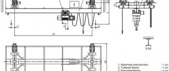
The overhead grab crane is equipped with a special beam along which the unit with the grab winch mechanisms installed on it moves. The box beam can be single; there are installations with a double guide. At the ends of the beam there are running trolleys that move along guide rails. The overhead crane is equipped with lifting winches equipped with electromagnetic hydraulic brakes, ensuring quick stopping.
The magnetic grab crane is distinguished by the installation of 2 load-handling devices - with electromagnets and a standard bucket. The units are mounted on a common or separate trolley. Excitation coils are installed on the magnetic section, which create a field when electrical voltage is applied. The technique is used when moving ferromagnetic materials and standard bulk cargo, as well as scrap steel.
The operator's workplace is equipped with a separate adjustable seat with joysticks installed on the armrests. The remote control allows you to perform manipulations from the cabin or from a distance from the grab crane.
To increase safety, the grab is equipped with:
- a limit switch that automatically turns off the lifting mechanism;
- sound alarm;
- limit contact switches limiting the travel of the trolley;
- built-in thermal switches to protect electric motors;
- contact travel limiters;
- work area lighting system.
Kozlova
The grab gantry crane is a type of bridge crane. The span of the machine is mounted on supports equipped with wheeled trolleys. The units move along rail tracks laid on concrete foundations. Visually, the supports resemble trestles, which is what gave the cranes this designation. There are semi-gantry-type installations, one of the sides of which rests on special racks, and the other on crane tracks.
To move the installation, movement mechanisms mounted on single-wheeled or balancing trolleys are used. There are various designs of gearboxes and couplings for connecting output shafts and wheel axles. The trolleys use band brakes to ensure quick stopping.
Shipping
Transportation of overhead cranes is carried out in different ways, but most often delivery is carried out using railway platforms. The main beams are shipped assembled. Parts of bridge structures that have large spans are transported in 2 or 3 sections.
If the lifting mechanism has a small load capacity, the carts are transported assembled. Production requires heavy-duty trolleys; they are transported in units. The frame and lifting mechanism are transported separately; if necessary, the balancers are moved from place to place.
The choice of transportation method depends on the size of the crane. If it is large, the structures are transported on separate railway platforms. It is possible to organize a coupler of 2 elements, but they are suitable for delivering cargo whose length does not exceed 17 m. For this purpose, platforms are used whose lifting capacity is 50 tons and 60 tons.
If the loads are oversized, you need to pay attention to the quality of their securing
It is important to take into account loading conditions. The parts of the crane must be securely fixed in place; to do this, wooden beams are placed under them
This reduces the mobility of the elements; they do not move during transportation. The crane is fixed to the platform using guy wires. It is necessary to make a strength calculation, determine the effective dynamic loads and the magnitude of the impact of inertial forces
The parts of the crane must be securely fixed in place; to do this, wooden beams are placed under them. This reduces the mobility of the elements; they do not move during transportation. The crane is fixed to the platform using guy wires. It is necessary to make a strength calculation, determine the effective dynamic loads and the magnitude of the impact of inertial forces.
If railroad tracks cannot be used for transportation, the crane is loaded onto semi-trailers. To transport them, powerful tractors or tractors are used. The enterprise must choose appropriate courses of action.
Maintenance, repair and modernization
Repair of overhead cranes is not often required, because the structure has a long service life. Much more often it is necessary to fix minor problems and adjust the operation of the device. Before starting a shift, the driver is required to check the condition of the crane.
Diagnostics of an overhead crane, as well as routine repairs, must be performed by specialists. They are engaged in the following list of works:
- Maintenance;
- mechanical department diagnostics;
- inspection of additional equipment;
- replacement of worn-out devices;
- bearing inspection;
- adjustment of nodes.
Minor problems can be fixed at the enterprise, but major breakdowns require dismantling the structure. If necessary, specialists can upgrade the devices. The work is carried out in accordance with the requirements of GOST.
Specialists can replace hook suspension or cable suspension, check instruments and safety devices, and inspect suspended equipment.
Repair work is of the following types:
- planned;
- major repairs;
- emergency.
Planned ones are performed to prevent breakdowns. During the work, the technician diagnoses faults, lubricates mechanisms, and adjusts components. A technical inspection of the overhead crane is being carried out.
Overhaul includes a wide range of works. It is necessary for cranes whose service life has already expired. Emergency repair is needed when a device fails. The technician identifies the problem and fixes it as quickly as possible.
Electrical diagram
The electrical circuit of an overhead crane depends on the model of the device, but the following main points can be highlighted:
- When drawing up a diagram, a specialist must take into account options for protecting the system from voltage surges.
- The crane is protected from overloads. Emergency braking and engine stop mechanisms must be provided.
An electrical diagram is required in order to repair electrical equipment. It consists of special characters that characterize nodes. Rectangles represent moving contacts, filled circles indicate stationary elements. Sweeps mean drum controllers. Their position is determined by lines running parallel. They are signed with numbers at the top.
Among overhead cranes, a distinction is made between cranes with manual and electric drives for lifting and moving mechanisms. The latter are most often used at large enterprises, since they allow servicing workshops and warehouses with large cargo traffic.
Overhead cranes with an electric drive have a very wide range of loads, so the power of the electric drive can vary over a fairly wide range - from several hundred watts to 1000 kW or more. Crane electrical equipment must be designed for special operating conditions: cyclic intermittent operation with a number of on/off switches reaching 500-600 per hour, constant overloads during acceleration and braking of mechanisms, a wide range of speed control.
The electrical equipment of an overhead crane is divided into main equipment, which ensures the movement of the bridge and cargo trolley and lifting/lowering of the load, and auxiliary equipment, which performs various additional functions not directly related to the main operation of the crane.
The most widely used method is the combined method of supplying power to the electrical equipment of the crane: a trolley line is laid along the crane track, and current is supplied to the engines of the cargo trolley using a garland suspended on the bridge. In some cases (for example, in explosive workshops), current supply via a flexible cable is used for both the load trolley and the bridge.
The electrical equipment of the crane must ensure trouble-free, reliable operation of all machinery mechanisms in any conditions and over a wide range of loads.
Failure of crane electrical equipment inevitably leads to the crane stopping, i.e. to downtime of expensive equipment and skilled workers servicing it.
Single rope grabs
Single-rope machines are usually called those in which both working movements (ascent or descent, closing or opening) are carried out by one traction element, mainly a rope. Single-rope designs can be automatic (with a bell) or manually controlled when deployed.
Currently, single-rope automatic ones (with a bell) are not used due to the complexity of the design.
In Fig. Figure 1 shows a single-rope Ginstalmost grab. The grabs consist of jaws a, middle crossbar b, upper crossbar c and jaw crossbar e.
Traverse b is guided by a bar. Latches are installed in the traverse d. The grab is suspended from the crane hook by means of a special cross-beam d. For smooth opening, an oil brake e is used, connected to the cross-beam b and jaws a. In the closed position, traverse d is closed with traverse b (Fig. 2, C). If you pull the rope k, the levers M and N will take the position shown in the dotted line. The beveled supporting surfaces of the latches p, under the influence of their own weight, slide off the traverse g, the latter lowers, and the grab opens. When lowering it onto the material of the traverse hook d, and along with it the traverse b is lowered until the latter reaches position a (Fig. 2, B). The latches move from position I to position II, and lever N, under the influence of its own weight, falls into the gap between both latches, taking its previous position (Fig. 2, A); traverse g closes with traverse b, and with further lifting of the hook the grab closes.
The speed of opening and closing of the jaws is controlled by an oil brake (Fig. 3), which is a cylinder with cavities A and B, connected by a valve that regulates oil flow. When opened, oil flows from A to B through valve L, which is adjusted using a set screw. Spring R (Fig. 2, B) holds the lever in its position and only by the force of the rope k can it be compressed and the latches p open.
It is advisable to use single-rope ones where the same reloading device must be used for reloading both bulk materials and piece goods. This occurs in foundries, on construction sites, in slag ditches when cleaning steam locomotives, etc.
Motor grabs
In motorized ones, the closing and opening of the jaws is carried out by a traction element (chain or rope), driven by an electric motor mounted on the frame.
The advantages of motors are as follows:
- independence in the process of closing from the crane winch, meaning that the motor one can be suspended from the hook of any crane;
- the motor one may not open to its full opening value, which is important where complete unloading is not required (foundries, etc.);
- When closing the motor jaws, there is no vertically directed force of the traction rope inherent in two-rope ones, as a result of which the closure of the grab occurs better.
Disadvantages of a motor grab
- high dead weight;
- complexity of the design and therefore relatively high cost;
- due to the current supply conditions, the motor cannot be used over long distances (warehouses);
- the impossibility of quickly lowering, hence not always sufficient immersion in the material.
Due to these shortcomings, the motor one has not become particularly widespread. The capacity of motor engines does not exceed 3 m3.
Types of general purpose overhead cranes
Bridge support cranes come in the following types: single-girder and double-girder manual hook cranes, as well as electric hook cranes.
Bridge support cranes come in the following types: single-girder and double-girder manual hook cranes, as well as electric hook cranes. Single-beam manual hooks consist of one beam, which is connected to the end beam. It is in this place that the wheels are mounted. To ensure that the bridge is sufficiently strong and rigid, the end and span beams are connected by struts. The wheels are made to rotate by the transmission shaft and gear, which extend from the traction wheel with a chain.
Worm steel is used for the load lifting mechanism. Double-girder manual hook cranes consist of two beams, which, as in single-girder cranes, rest on end beams. The movement mechanism is represented by a wheel with a chain. The design of the trolley has a frame with wheels. The cart is driven by a sprocket wheel. The frame has a mechanism for lifting loads, equipped with a brake with wheels and a chain.
Single girder electric hook cranes. Here the cargo trolley is represented in the form of electric ropes. The bridge also has one beam, which is supported by box-type end beams. The ends of the beam are braced, which are designed to enhance strength and rigidity. Movement occurs using a separate drive, that is, each wheel is equipped with a drive separately from the other wheel.
This type of crane does not have a brake, as the movement speed is very low. All crane mechanisms are powered via a cable. This type of crane can be controlled either using the control panel or from inside the cabin. Double-girder electric hook cranes have a bridge and a load trolley. The bridge has a movement mechanism, and the cargo trolley has almost all the mechanisms found in the cranes. This includes a load lifting and movement mechanism, a crane control system, and much more. The control is similar to the control of an electric single-girder crane, that is, both using the control panel and from inside the cabin.
Electric magnetic overhead cranes. Their design is the same as that of electric hook cranes. Only this type of crane has a magnet that is attached to the hook. The magnet supplies direct current with a voltage of 220V. The magnet on the crane can be removed and the crane can then be used as a hook crane.
Electric grab overhead cranes. The device is the same as that of hook cranes. The only exception is the device of the trolley. It has two lifting mechanisms: one for lifting the grab ropes, and the other for lifting the load.
Electric hook overhead cranes designed for lifting large loads. The device is the same as that of double girder cranes.
Electric hook overhead cranes designed for lifting large loads. The device is the same as that of double girder cranes. The bridge of such cranes must be located on eight wheels. This ensures significantly less load on the wheels. In order for the crane to be rotated, the hinges are in contact with the rails. The rails, in turn, have some deviation. Movement is ensured using a separate drive.
The crane can be controlled remotely if the crane operates in workshops that do not contain explosive substances, toxic gases, or substances that destroy metal and cause erosion. There are three types of remote control. Control using a special remote control, using a remote control that can be rearranged, and using radio control.
General purpose overhead cranes can also be suspended. They are single-span, double-span and three-span. Such cranes are very convenient because they are small in size, they can be installed anywhere in the workshop, they can cover large spans and ensure the movement of a trolley from one crane to another. These cranes are also used in hard-to-reach places where it is not possible to operate with any other type of crane.
Manual single girder single span cranes have a beam attached to the bottom of the end beams. A manual hoist is used as a lifting mechanism. Electric single girder single span cranes also have a support beam attached to the lower end beams.
Both driven and non-driven electric hoist trolleys serve as the movement mechanism. The taps are made without butt locks, but a power cable must be present. Electric single girder double span cranes differ from single girder electric cranes only in that the main girder is attached to three cross girders.
Features of overhead cranes
The crane bridge consists of two beams that are attached to the main one. Beams are small boxes or cubes, have a horizontal belt (upper and lower), as well as two vertical walls. The edges of each rail are reinforced with special supports, this is done in order to limit the movement of the bridge within the bogie. The side platforms of the beams have special transitions designed for workers to access the mechanisms and structure of the crane. This ensures hassle-free repair of damaged crane parts.
An overhead crane must have a supporting structure, a mechanism for lifting the load, as well as a hook that is used to hook the load and lift it. All of the above mechanisms are driven by an electric drive.
Depending on where the crane is used and what tasks it performs, the overhead crane should be:
- workshop;
- construction;
- transport;
- deck
The workshop crane is designed for loading and unloading cargo located at the enterprise in special workshops. It is usually located along the entire length of the workshop. These cranes consist of a lifting bridge and a trolley. There are also special cranes, for example, metallurgical ones. They are used in foundries.
The crane beam has a main beam, that is, a bridge, which is located above the span, as well as end beams. The design of the crane beam includes a carriage and a mechanism designed to lift the load. The double girder overhead crane is used in unloading and loading shops, indoors and outdoors. The single girder crane is used for lifting work in buildings and workshops in industry.
Each crane has mechanisms for grasping loads of various shapes and designs. These gripping mechanisms also each have their own function.
The hook grip mechanism is equipped with hooks for loading and unloading single loads. If you need to reload bulk solids, use special buckets. A grab mechanism is used specifically for reloading bulk substances.
It is a type of bucket that is opened using a special drum. Magnetic – is a hook with a magnet and is designed to move iron loads. A very versatile and compact mechanism – magnetic clamshell. Mold - this mechanism has a box that is used to transport crushed metal. The beam crane has special gripping arms that grip small loads.
Source
Excavators
Rope grabs
On mechanical cable excavators, both double-jaw grabs and grabs with a large number of jaws are used - the number and shape of the jaws depend on the type of material being handled. However, the basic diagram of their operation does not differ from the diagram of a double-jaw grab.
Description
For a grab used on a mechanical excavator, a dragline lattice boom is used. Three types of grabs are produced for excavators: light, medium and heavy. In this case, the mass of the grab used should be greater, the denser the soil. However, the heavier the grab, the less soil it can lift for a given equipment stability, which affects its productivity.
Device
To prevent twisting of the ropes and significant swinging of the grab when turning the platform, a pull-out device called a damper is used. The damper acts on the bucket with a pull rope. A constant rope tension, independent of the position of the grab, is created by the weight of the load moving inside the boom along the guides, to which the rope bending around the blocks is attached. Some excavators use a friction mechanism for opening the bottom of the bucket, on the drum of which a rope is attached.
Advantages and disadvantages
The disadvantage of the rope grab is the inability to develop dense soils: the load from the mass of the grab is not enough to crash into the ground.
Hydraulic grabs
On hydraulically driven excavators, special rigidly suspended grabs are installed, which are mounted on the handle of a backhoe instead of a bucket.
Advantages and disadvantages
The main advantage is the ability to create the necessary pressure when cutting into the ground and, regardless of its mass, to develop dense soils.
Construction of a double girder overhead crane
The movable bridge of the crane consists of 2 parallel beams of a box-shaped, solid-wall or lattice structure, depending on the load capacity.
Due to the connection with the transverse end beams on which the chassis is located, the double-girder overhead bridge crane moves along the rails of the crane tracks in the upper part of the production workshop or external overpass. The rails are mounted on crane beams, which are attached to building columns or ground supports.
Lifting of cargo is carried out by a lifting mechanism of a cargo trolley moving along the bridge. The trolley has a welded frame, is equipped with one or two lifting mechanisms with a gearbox and a moving device with a low-speed shaft to evenly distribute the load on the running wheels.
The overhead crane is driven by gear motors operating synchronously. Electricity is supplied via trolleys laid along the span and supplied to the hoist through a flexible cable. The crane is controlled from the cabin, or from a radio remote control on the floor.
You can familiarize yourself with the diagram of a double-girder overhead crane on our website.
The double girder overhead crane has the following main characteristics:
- operating mode (“A”) - a total of 6 gradations, from “rare” to “very heavy”. The indicator depends on the combination of the class of use and load of the crane;
- load class (“Q”) is divided into “light”, “moderate”, “heavy”, “very heavy”;
- class of use (“U”) - divided into 9 positions, depending on the number of operating cycles over the entire service life of the PMG.
The main characteristics must be taken into account when choosing the parameters of a double-girder overhead crane before purchasing, in order to prevent premature wear and failure of the hydraulic transmission unit under excessive loading.
To avoid making a mistake with your choice, seek advice from our specialists.
Parameters of Double Girder Electric Overhead Cranes
- lifting capacity – from 1 to 500 tons (includes the mass of the cargo, taking into account the lifting device and container);
- lifting height – from 3 to 52 m;
- lifting speed – from 2 to 40 m/min;
- trolley moving speed – from 40 to 60 m/min;
- crane speed – up to 125 m/min;
- span length – from 4.5 to 34 m (distance between the axles of the crane wheels);
- temperature range – from -40 to +40°С (depending on operating conditions and climatic design of the crane);
- type of placement – U1, U2, U3 (outdoors, under a canopy, indoors);
- execution - explosion-proof, fireproof, tropical, special (equipped with load-handling mechanisms).
Types of grab equipment, their design features
The modern market of hydraulic equipment offers a large number of different models of grabs, which differ from each other not only in size and production technology (depending on the manufacturer), but also in other indicators:
- load capacity of the device;
- kinematic characteristics of the equipment;
- drive.
Depending on the load capacity, grabs are divided into groups:
- Very light group - used when loading or unloading coal dust or lime, permissible bulk density, which ranges from 0.4 to 0.63 t/cub.m.;
- Light group - permissible bulk density from 0.8 to 1 t/cub.m. and is intended for small and medium crushed stone, coal, alumina and other powdery bulk materials;
- Middle group - used for large crushed stone, broken brick, cement, gravel or fine clay, gypsum. Bulk density - from 1.25 to 2 t/cub.m.;
- Group of heavy devices - designed to work with hard and rocky rocks, the bulk density of which is from 2.5 to 3.2 t/cub.m.
The principle of operation in different models of load-handling devices is the same and is based on the use of a large iron bucket (scoop) with opening jaws, with which you can grab various types of materials and manipulate them. Grab grabs, depending on the kinematic feature, are divided into two main types: rope and drive units.
What is a beam crane and its use in the modern world
A beam crane is a machine that is designed to carry out work to ensure loading, as well as work to ensure unloading. Often such machines are used in various warehouses, they are also used in port areas. Such machines operate in open space. As a working body, this machine can use not only a hook suspension for lifting piece goods, but also on such machines they use clamshell buckets, which open and close using a rope system and pulley blocks. These devices - grabs - are used for loading and unloading various bulk materials, such as coal, sand, crushed stone, asphalt and other similar materials. Modern companies specializing in the production of industrial capacity are now experiencing a real surge in activity. Of course, because their equipment is now in great demand. The hero of our story is just from such a list. The leaders in production are large, established companies, such as CJSC Trading House Lifting and Transport Equipment, for which beam cranes Yekaterinburg are the primary area of production
This company also installs them at the customer’s site, which is also important. Let us now take a closer look at the very structure of this complex production element.
The suspended beam crane itself is a machine, the main frame of which is made of angle profiles and channels welded together, which together form a lattice structure. There is also an option with a frame design in the form of a beam. A cargo trolley is installed on it, which moves along rails installed along the crane frame. Lifting equipment (winch) is installed on this cargo trolley. This equipment, like the entire machine, is electrically driven. It consists of an electric motor that transmits torque through a clutch (on top of which a brake (block type) is installed) to a gearbox (helical). And from the gearbox, the moment is transmitted to the drum. Transmission is provided through the connection of two gear coupling halves of the gearbox and the drum.
The drum ensures by its rotation that the rope winds and runs away from it. Steel rope. At the end of the rope, a working body is installed, which, as noted earlier, can be either a hook suspension or a rope grab. What kind of working body a given crane has is determined by its purpose, or in other words, where it works.
The longitudinal movement of the cargo trolley along the frame is provided by an additional drive, which moves the trolley using a rope. There is one more element worth noting here.
Able to quickly lift heavy loads without putting operating personnel at risk. An electric hoist is a suspended type lifting device with an electric drive. It is used to move objects vertically and horizontally.
The entire frame with the cargo trolley is mounted on two racks. These racks come with double support or single support. Also racks can be rigid or flexible. It can be made of profiles, that is, it can be lattice, or it can also be made of a tubular structure.
The movement of the crane is ensured by wheels for moving on rails, which are installed at the bottom of the crane racks. Each wheel block is equipped with an individual electric drive. The movement itself is carried out on rails.
A cabin for the crane operator is also installed on the frame, from where he operates the machine; usually the cabin is located under the frame.
The faucet is powered by electricity, which is supplied through high-voltage wires.
sprosi.com.ua
Classification
Depending on the design of the lifting mechanism, grab cranes have different designs:
- Rope grab installations. Opening and closing of the bucket occurs with the help of closing and supporting ropes. There are single-rope, double-rope and four-rope grab cranes. It is considered more appropriate to use four-rope units that have a paired coupling of both types of slings. This device allows you to create maximum closure of the bucket, due to special pulley systems. They are designed to transport cargo with volumes from 0.4 to 16 m3.
- Motorized grab cranes. The load-handling element consists of several parts and is driven by an electric crane drive. The device transmits a signal to the drum and pulley system, which ensure opening and closing of the bucket. This sample is the most repairable.
- Hydraulic tap. The operation of the machine is ensured by hydraulic equipment—hydraulic cylinders and a hydraulic station. They can be used for wet cargo with high density.
The modern look of the load-handling body has also acquired a number of modifications for ease of working with various materials:
- For bulk raw materials, the lifting equipment is a two-jaw volumetric bucket.
- To transport round timber, pliers are used. There may be two or four. The extended traction device is designed for wet and thermal processing of wood.
- Multi-jaw grabs for metal. Depending on the volume of work performed, there may be 4-8 jaws of different types. They have a high load capacity. This modification is often supplemented with an electromagnetic device for efficient transportation of metal structures. The lifting electromagnet is represented by a cast steel body with a high magnetic permeability. The magnet is connected to the valve body by welding or bolts.
- Grab cranes with reduced height. Their use is advisable for use in confined spaces, for example in an industrial workshop. Their design is lightweight due to the absence of traverses. Moreover, such units have a small mass, with a scooping capacity of up to 0.6 m3 on average.
- Grabs for crane installations. They are compact in size, light in weight and multi-functional. There are various configurations and forms of devices, both for working with metal and wood, and for sand.
Grab cranes are designed to handle heavy loads. Their main feature is the structure of the load-handling element, which is a volumetric bucket for lifting and transporting bulk materials. Modifications of grab cranes are different, depending on the volume and type of work performed
Manufacturers pay attention to the versatility of technological processes performed using such lifting machines. Therefore, manufacturing plants are ready to produce components for grab cranes according to specified technical conditions
The high productivity and efficiency of this equipment determines its popularity in industrial production.
Rope grabs
Ropes and drum winches allow the production of mechanical force without a rigid kinematic connection between the gripping elements when closing and opening the jaws. The control of a single-rope grab is available to the crane operator from the cab. The equipment is suitable for handling bulk materials and piece goods. Changing the load-handling attachment is carried out without wasting time by removing the bracket from the hook of stationary and mobile cranes. Mounted on an excavator or loader.
Operating principle of a single-rope grab:
- It descends with its mouth open and is inserted into the load.
- The load is grabbed and the jaws close.
- Lifting, moving to the unloading point.
- The opening of the jaws occurs upon contact with the surface - loosening the tension of the rope opens the closing latch.
- When lifting, the bucket is emptied and ready for the next cycle.
There are accelerated unloading options:
- Self-unloading - at a given height, the hanging bell automatically opens the latch of the bucket blades.
- Unloading at an arbitrary height - the stopper is controlled from the ground or from the cabin (disabling the blocking by a tensioning cable device).
Multi-rope load grippers are more efficient to use due to the ease of control. With the integration of the pulley system, the power characteristics when raking and deepening the jaws when digging loose soils are improved.
Description of the operating principle and design of overhead cranes of various types
This is a lifting machine, the gripping device of which is located on a mobile trolley (or hoist), which in turn moves along the bridge. The latter is a movable structure made of high-strength steel. An overhead crane can be equipped with various gripping mechanisms: a bucket, a magnet, a grab, a device for lifting containers, and so on.
The peak production of these lifting machines occurred in the 80s of the twentieth century: 6,000-7,000 models of various lifting capacities rolled off the assembly lines of Soviet factories every year.
Since the 2000s, overhead cranes have been produced in quantities of up to 1,500 units (if we count manufacturers from all countries of the former Union). But they are made by specialized factories that develop and offer new solutions for specific construction tasks.
GENERAL DEVICES.
- CART.
The overhead crane trolley is shown separately in Fig. (12.6).
On frame 11
The trolley contains the main and auxiliary lifting mechanisms and the trolley movement mechanism.
The main lift mechanism has an electric motor 9
connected by a long insert shaft to a gearbox
19.
The half-coupling connecting the insert shaft to the input shaft of the gearbox is used as a brake pulley for the shoe brake
1 ,
driven by an electrohydraulic pusher.
The output shaft of the gearbox is connected by a gear coupling to a drum 10
.
The supports of the upper pulley blocks 3
and the leveling blocks
2
are located on the upper surface of the frame, which facilitates their maintenance and increases the possible lifting height. A spindle switch is used as a lift height limiter, turning off the current when the hook suspension reaches the extreme upper and lower positions.
The auxiliary lift mechanism has a similar kinematic diagram (motor 15
, gearbox
18
, drum
17
, limit switch 13).
Both lifting mechanisms are equipped with hook suspensions (20
– for the main and
16
– for the auxiliary lift).
11 pages, 5134 words
Metallurgical crane
... In accordance with GOST 25546-82, most metallurgical cranes are classified as heavy (T) and very heavy (VT) operating modes [1]. The lifting height of the main bogies varies from 1.2 to 36 ... the machine has two movement mechanisms and rail tracks for the driving front wheels of the bogie, located on the two main beams of the bridge. On the belts of these beams on the inner sides there are...
The trolley movement mechanism consists of a motor 4
¸brake
5
, vertical gear reducer
6
, two driving
7
and two idler
14
running wheels.
8 is mounted on the frame of the trolley ,
acting in extreme positions on the limit switch, which limits the path of movement of the trolley.
- TROLLS
Trolls are usually made from rolled angle steel. To supply current to the crane, sliding-type current collectors are used, attached to the metal structure of the crane, the shoes of which slide along the trolleys when the overhead crane moves.
For maintenance of workshop trolleys, a special platform is provided on the crane. For current supply to motors located on the trolley, trolleys made of round or angle steel are usually used. Their installation requires special racks on the platform running along the main beam. Therefore, in the latest designs of overhead cranes, the current supply to the trolley is carried out using a flexible cable suspended on a wire. The use of a flexible current supply simplified the design, increased operational reliability and reduced the weight of the crane, as it made it possible to abandon the racks and the platform for their placement and maintenance.
- TRAVEL
When reloading long loads (sheets, rolled products), lifting electromagnets are blocked on crossbeams, to which they are suspended by means of load chains. The crossbar is connected to the crane trolley using a flexible or rigid suspension.
With a flexible suspension, the traverses are suspended on edges directed away from the lifting mechanism. With a large traverse length (6-16 m), a significant distance between the drums is required.
Traverses are box-shaped beams of constant, and if long, variable cross-section. The traverses are suspended on the hooks of the crane suspensions; 2-4 magnets are attached to their lower part. When four magnets are directly suspended from the traverse, there may be no contact between the two magnets and the non-flat surface of the load. To ensure reliable contact of all magnets with the load, the magnets are connected in pairs by a lever-balance system. With such a system, both four magnets and two middle ones can work when the outer ones are turned off.
At high speeds of translational movement of magnetic cranes, it is rational to use flexible rope suspension traverses, due to which the swing of the load in one or two directions is reduced.
Classification of overhead cranes
Classified by design:
- Support cranes, the bridge structure of which rests directly and from above on the rail track along which it moves.
- Suspended - models attached to the rail track from below, to its shelves.
- Gantry cranes are cranes whose bridge is mounted on a rail track using supports.
Models are classified according to their load capacity:
- The first group - those working with a weight of up to 5 tons;
- The second group - lifting up to 50 tons;
- The third group - designed for a weight of up to 300-320 tons.
According to their purpose, clans are classified into:
- General - solve standard construction problems;
- Special - provide specific lifting operations.
By type of drive there are:
- Manual - Required to operate a winch to perform work tasks.
- Electric - they operate without operator participation, from the network.
Purpose of gantry cranes
Gantry cranes are designed to carry out work on transporting piecemeal, large and long cargo. These can be concrete building structures, timber, rolled steel, industrial profiles and products. Bulk cargo such as coal, crushed stone, sand is moved by crane in a special container.
Gantry cranes of various types have a lifting capacity from 3 to 50 tons with a span of 10-40 meters. Such multifunctional operating parameters allow the units to be used for various purposes: in shipbuilding, mechanical engineering, at railway stations and warehouses.
General structure of an overhead crane
The bridge design of each model is very simple: it is a connection of two box-section spans with end beams. Together they form a rail track, with stops at the ends to block the movement of the trolley.
Each span beam has 2 horizontal chords
- upper
- lower.
Support cranes are installed on the first one, and suspended cranes are installed under the second one. The span beam also has large and small diaphragms for stability and more uniform load transfer. In order to be able to service the overhead crane, special platforms are mounted on the span beams.
A trolley moves along the rail track - in the general case, a frame with mechanisms for moving and lifting loads attached to it. The assembly diagrams for each unit are usually unified.
The frame itself is the intersection of longitudinal and transverse beams with the flooring. The trolley can also be equipped with a fencing buffer, hook lift limiters, and a ruler for fixing extreme positions. It typically weighs between 0.2 and 0.4 times the lifting capacity (Q) of an overhead crane.
The trolley moves through a movement mechanism equipped with cylindrical wheels and made according to one of the unified schemes. It can have a central drive for both wheels at once or separate for each, a mounted gearbox and a brake. And the wheels themselves can be not only cylindrical, but also conical, with the apex mounted both on the outside and on the inside (in the latter case, only non-drive ones).
GENERAL INFORMATION
Overhead cranes are used in workshops of repair enterprises and production workshops of construction industry enterprises.
The designs of special overhead cranes are very diverse. These cranes can be sliding along crane rails or rotating around a vertical axis. Rotating cranes include chord, radial and rotary.
Translationally moving overhead cranes have single-girder and double-block bridges with a normal span length or increased to 40-60 m.
The carrying capacity of these machines is 400-500 tons or more.
Page 16 shows a 16/3.2t general purpose overhead crane.
Progressively moving overhead cranes are often equipped with hooks, brackets or special load-handling devices (magnets, grabs, mechanical tongs).
Bridge cranes are equipped with trolleys designed to lift and move loads along the span. Carts can move on rails, mounted on the upper or lower chords of bridges. Carts moving along the lower chords of bridges can move along transition bridges from one bay of the workshop to a nearby one. Walkways with rails for trolleys are located under the crane beams and have trolleys for powering electric motors.
7 pages, 3069 words
Lifting machines Overhead crane
... group – 1862 MPa. Type of wire coating – galvanized for moderately aggressive working conditions; the combination of directions for laying elements is one-sided; method of rope laying - ... cranes are mounted on rolling bearings; the use of non-ferrous metals for bearings is completely excluded. 1 Calculation of the lifting mechanism Having designed a hook suspension having the following parameters: Qп = 200 t; operating mode...
Carts moving along the upper and lower chords of bridge beams can be equipped with rotating booms, slewing bearings and rotating parts rotating around vertical axes. Booms equipped with load-handling devices are located on the rotary axes.
Overhead crane mechanisms provide three movements: load lifting, trolley movement and bridge movement. The lifting mechanism is a winch connected to a double pulley; with a lifting capacity of more than 10 tons, the cranes are equipped with two independent lifting mechanisms - the main and auxiliary, having a lifting capacity equal to approximately 0.25 of the main one, and used for lifting small loads at high speed. The lifting mechanism of the grab crane is made in the form of two identical independent lifting mechanisms, the electric motors of which are controlled by two controllers that have a common control handle. The trolley movement mechanism has two idle and two drive wheels, rotated by an electric motor through a gearbox.
Applications of overhead cranes
- Carrying out periodic, one-time or permanent lifting operations in the absence of current supply. In such cases, manual overhead cranes, both overhead and support, are especially in demand.
- Lifting and moving operations in large indoor areas, for example, in production workshops, machine rooms, warehouses. In such cases, the relatively high performance of electric overhead cranes is convenient; both support and suspended models are in demand.
- Lifting work on small construction (and other) sites, both open and closed. In such conditions, it is more advisable to install and use manual, support or overhead overhead cranes.
- Operations with bulk cargo - for their implementation it is necessary to use models equipped with grabs.
- Work on lifting and moving loads with magnetic properties - this requires electric, usually support bridge cranes.
Source
Muldo grab overhead crane
The main difference from a general industrial crane is the presence of a powerful magnetic device, which is mounted on a traverse or directly on the crane itself. If the attachment is made to a traverse, then the number of electromagnets varies. There are two types of magnet shapes:
- rectangular (to increase the adhesion area and lift flat, large-area loads);
- round (used for lifting and moving heavy loads).
Charges are widely used in this type of crane. A mold crane with a grab or magnet is necessary to work with an electromagnet, which ensures loading/unloading of a mold or metal, its turning and transportation.
The main area of application is metallurgical plants, namely workshops where the operation of molds is necessary, as well as enterprises involved in the processing of secondary metal.
Specifications
The operational capabilities and scope of such devices are determined by the following characteristics:
- the size of the boom increase (it is measured in meters and ranges from twenty-five to forty meters);
- load lifting height (individual cranes can lift loads one hundred meters or more);
- load lifting speed (this parameter reaches 200 m/min);
- a parameter that determines the rotation of the tower (from 0.2 to 1 rpm);
- speed of movement of the chassis.
The listed parameters are determined by the list of tasks to be solved. All types of tower cranes comply with the accepted classification. It is approved by existing standards.
The marking includes a sequence of capital letters and a set of numbers. The first three letters indicate the type of product. For example, K (crane) B (tower) M (modular). The following numbers indicate: group number, type of base model, serial number of the entire unit.
- The group number determines the magnitude of the load moment.
- The appearance of the base model indicates whether the tower is rotating or not. Numbers from 01 to 69 indicate mechanisms with a rotating turret. Rooms 71 to 99 with fixed tower.
- The serial number of the design indicates design changes.
At the end of the marking the climatic version of the specific product is indicated. For example, the letter “U” indicates the use of a crane in a temperate climate, “HL” in a cold climate.