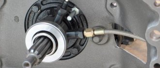
In the classic design, there was no flywheel bearing due to the insignificant weight of the clutch elements, which were physically located outside the gearbox. Then a needle bearing began to be pressed into the flywheel, the purpose of which still remains a mystery to drivers. The main difficulty is the high price of the original consumables online, and the lack of bearings on the shelves of physical stores.
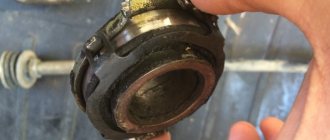
Bearing inside flywheel
Bearing inside flywheel
The flywheel belongs to several vehicle systems, as it solves various problems:
- when starting the engine, it engages with the starter’s bendix, spins up to accumulate kinetic energy, and turns the crankshaft at the initial stage;
- then a massive part, again due to the accumulated kinetic energy, rotates the shaft from the dead points of the piston;
- the flywheel compensates for jerks and uneven angular velocities of the crankshaft at different times during the fuel ignition cycle;
- The flywheel centering bearing increases the life of the gearbox input shaft, which periodically enters the cage when the clutch is depressed.
Flywheel purpose
Purpose of the bearing inside the flywheel
It is worth noting that the bearing is not found in all flywheels, regardless of the year of manufacture of the machine. For example, Ford Transit began to be equipped with this unit back in 1987, but domestic VAZs still do not have it.
Why is it needed?
Rotation in the transmission system is transmitted from the internal combustion engine shaft to the wheels through the gearbox using a clutch disc and basket mounted on the flywheel. The scheme, in principle, is not complicated, but the clutch elements are removed from the gearbox, exposing the input shaft to intense wear.
To reduce imbalance, a kinematic scheme is used:
- a needle bearing is pressed inside the flywheel with little force;
- at the moment of engagement of the disk with the basket, the input shaft changes its spatial position - it extends a few millimeters out of the box towards the crankshaft and the flywheel mounted on it, respectively.
The designers considered that this translational movement was quite enough for the free end of the gearbox input shaft to fit inside the bearing race without much effort and to receive additional temporary rotation support.
Even under light loads, the bearing cannot have an eternal life, so periodic replacement of the consumable is required. The main problem for the user is how to remove the needle bearing without removing the flywheel itself:
- When dismantling, manufacturers recommend replacing the mounting bolts;
- before removing the flywheel you need to put marks;
- After installing the part back, it is advisable to balance the crankshaft assembly on a dynamic stand.
Replacing the rolling support
All these operations sharply increase the engine repair budget; a simple bearing replacement results in partial disassembly of the gearbox, engine and clutch.
Should I install it or not when replacing?
The user most often detects a malfunction of the rotation support by ear when an extraneous grinding noise appears. After disassembly, a bearing is found inside the flywheel, and information about its purpose, markings and dimensions is not available in the manual or on the forums.
In addition, a friend or neighbor in the garage simply does not have such a part, so doubts arise whether this “consumable” is really necessary for the engine and gearbox. After a lengthy search on the Internet and city stores, several options are possible:
- the consumable is issued according to the catalog, arrives in 7 – 14 days, pressing is carried out using traditional methods and the bearing is replaced;
- the flywheel is removed, the rolling support is knocked out from the opposite side with a hammer, the user cannot find the bearing, partially restores the old one, fills it with lubricant and installs it in place;
- According to the advice of colleagues, the flywheel is mounted without a bearing at your own peril and risk.
Screw and impact puller
Experts recommend using an original part and installing it without fail if the car came off the assembly line with this configuration.
Two bearings using the example of Ford Transit produced 1987 - 2000
On the forums you can find information on upgrading the “bearing inside the flywheel” unit. For example, on Ford Transit modifications from 1987–00, the bearing was present in this clutch/flywheel/gearbox mechanism.
Taking into account the mileage of these foreign cars, experienced users pull out the worn-out bearing, and instead of one consumable, install two at once, one after another, motivating this with the following arguments:
- with significant wear on the input shaft groove, the effectiveness of the additional rotation support completely loses its meaning;
- the distant bearing in this case remains inoperative and serves as an ordinary bushing;
- The bearing closest to the input shaft of the box is working, protrudes slightly from the plane of the flywheel, and ensures reliable support of the input shaft when the clutch is engaged.
Two in-row bearings for Ford Transit
Thus, the repair budget doubles, but the input shaft and the entire gearbox last longer.
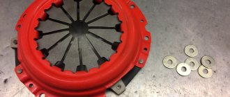
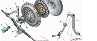
Clutch basket diagram and principle of its operation
The clutch basket or clutch is designed to separate the engine and gearbox. This ensures that the torque supply from the engine to the gearbox is interrupted, allowing for quick and safe gear changes and a smooth start-up.
The main components of the basket are two clutches : the main tractor clutch and the power take-off shaft (PTO) clutch. The type of couplings is dry (i.e., non-oil-lubricated) single-disc. Management is separate, constantly closed. The basket is installed on the engine flywheel.
The operating principle is as follows. The design of the basket includes three disks: driven, pressure and driving. Pressure springs provide constant pressure on the driven disk to the drive disk and to the flywheel of the motor. When the driver presses the clutch pedal in the cab, the shifter with the bearing moves, the lever and the PTO are disengaged.
The clutch basket separates the engine and gearbox
Dismantling in different ways
On the one hand, to reduce the repair budget, ideally the rolling bearing is replaced without dismantling the flywheel. At the same time, the main problem of repairing on your own arises - how to remove the bearing without special tools and devices. This manual traditionally presents techniques according to the principle from simple to complex.
Soap or bread
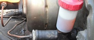
The flywheel is installed at the end of the crankshaft close to a seat specially designed for this purpose. Fixed with 5 – 8 bolts according to various fastening schemes. The bearing is installed in the flywheel body with a slight interference fit and can be removed quite easily, but access to it is limited.
The simplest “folk” method of removing a flywheel bearing is to fill the space of the inner race with thick plastic material. Most often, bread crumb or soap rolled out into plasticine is used according to the following scheme:
- the bread is stuffed inside the cage by hand flush with the outer plane of the bearing;
- a drift is selected, the outer size is equal to the inner diameter of the holder;
- light blows of the hammer on the punch crush the bread inside the bearing;
- by analogy with a liquid or plastic medium, the force from the pressure of the punch is redistributed throughout the entire volume of soap or bread crumb;
- the working medium penetrates under the rear surface of the bearing and pushes it out.
Dismantling with bread crumb
Soap or bread crumb is added inside after several light and precise blows of the hammer. The volume of these substances must be at least 1/3 of the volume of the rolling support. After the bearing body is pushed out halfway, the bearing is pryed up with a drift or hook and pulled out completely without much effort.
The technique has been tested on different machines, does not fail, and takes 10 minutes maximum.
Reverse hammer
There is a homemade and factory version of the device, the design of which differs from each other:
- a homemade reverse hammer - an analogue of a kit for installing the last row of laminate flooring near the walls;
- An industrially manufactured reverse hammer tool is a rod with a weight that moves freely along it, a collet clamp on the working surface, and a stop on the reverse side.
Reverse hammer in the form of a staple
Reverse hammer for removing bearings
To remove the bearing with a homemade device, one curved edge of the plate is inserted under the rolling support body from behind. The second hook is struck with a hammer, the force is transferred to the lower part of the tool, pulling the “consumable” out of its seat.
The factory version of the reverse hammer is much more convenient:
- the collet is clamped by the thread inside the holder;
- the weight hits the back of the tool;
- kinetic energy is transferred to the lower unit of the device;
- the bearing is pulled out of its seat with jerks.
A tool with 4 collet adapters for different diameters costs from 7,000 rubles. A homemade device is made in a quarter of an hour from scrap metal cutting.
An analogue of the factory reverse hammer can be made from a brass anchor of a suitable diameter. For example, for UAZ 3159 it is M12 16 x 50 mm, which costs about 50 rubles in Household Goods. You can weld the device from a rod and two metal washers:
- they limit the stroke of the weighting material placed on the rod;
- A piece of rod with a rounded end should be placed under the collet (bullet configuration).
Reverse anchor hammer
First, the device is driven inside the bearing race. The “bullet” enters the collet and expands it until the inner surface of the clip is completely compressed. Then, with light blows of the weighting agent in the direction from the flywheel, the bearing is pulled out.
Removed bearing on the return hammer sleeve
Two-bolt device
It is possible to make an improvised puller in a few minutes if you have two bolts and a crown or a steel cup. To do this you need to follow these steps:
- the head of the long bolt is inserted under the back of the bearing;
- a short bolt is used to wedge the previous fastener inside the holder;
- A crown with a hole in the center is put on the threaded part of the long bolt, resting its sides against the body of the flywheel.
Two bolt puller
When the nut is tightened, the head of the long bearing moves upward along the threads, pulling the bearing outward.
Screw puller
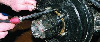
There are classic screw pullers with 3 sliding jaws for bearings. In this case, an internal puller is required for the rolling support unit:
- the paws are placed inside the clip;
- are hooked with the outer edges onto the bearing from the rear side;
- the working screw rests against the crankshaft body exactly in the center;
- when the screw is screwed in, the entire structure, together with the rolling unit, rises upward.
Screw Internal Bearing Puller
This tool costs 2 - 3 thousand rubles, but is suitable for different diameters of the holder, so it will be in demand in the garage of a mechanic who prefers to repair cars on his own.
Collet puller
Typically this device is sold complete with a reverse hammer and has the following design:
- a working screw is screwed into the center of the horseshoe stop;
- removable, collet screw tip.
Collet puller
The puller works on the principle of a screw device, but the clip is clamped with a collet along the inner diameter, and is not pryed off with paws from below, as in the classic version.
Bearing installation
The reverse operation of pressing the bearing does not require the same amount of effort that the technician makes when removing the rolling support. It is enough to use a head of a suitable size and a hammer as a mandrel. The main nuances of bearing installation are:
- the seat should be cleaned of remaining materials, especially after removal with bread crumbs or soap;
- the lubricant must be reliably protected by a cover; if it gets on the clutch, the quality of rotation transmission will decrease, and the disc will begin to slip inside the basket.
Bearing installation
Since the bearing is pressed into the flywheel, which sits on the crankshaft, and the gearbox shaft enters inside it, the coaxial rotation of these assembly units is necessary. Otherwise, imbalance of the input shaft will cause the replacement of all other gears.
Thus, if the flywheel of a particular engine has a needle bearing installed on a conveyor, it should be maintained and replaced with an original spare part or an equivalent permitted in the machine’s operating instructions.
If you have any questions, leave them in the comments below the article. We or our visitors will be happy to answer them
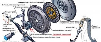
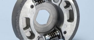
Clutch adjustment
With use, the driven disc linings are subject to friction and wear out. As a result, the gap between the ends of the release levers (paws) and the thrust bearing is reduced. Timely adjustment of the T 40 clutch feet restores the clearance and reduces friction.
The normal gap should be 4 mm. As this indicator decreases, the ends of the levers will begin to come into contact with the bearing, the clutch will begin to slip, which in turn will lead to increased friction and both parts will wear out faster.
The question of how to adjust the clutch on the T 40 tractor arises after the pedal stroke decreases to 2.5 cm. There is no need to measure millimeters before adjusting and wait for the exact value: when the pedal stroke decreases, it becomes more difficult to squeeze the clutch, it is “tight.” Adjustment can be done in two ways: using rods or bolts. Before you start working, you should watch a couple of videos to answer any possible questions.
T-40 clutch diagram
Traction adjustment
Procedure:
- First, open the upper hatch of the clutch basket housing. Underneath it is the axis of the traction fork, secured with a cotter pin.
- Unscrew the axle and remove the fork from the lever.
- By screwing and screwing the fork, we select the correct rod length, while simultaneously measuring the gap between the ends of the arms and the release bearing. It should be 4 mm.
- Having set the correct rod length, put the fork axle in place and secure it with a cotter pin.
- Install the hatch cover.
Be sure to read: How to adjust valves on a T-40
Adjustment by changing the length of the rod is quite simple, accessible to a novice mechanic and does not take much time. However, in some cases this method is not suitable. In this case, adjustment is used using adjusting bolts.
Bolt adjustment
Procedure:
- Open the top hatch of the basket and find the nut securing the bolts.
- Unscrew this nut.
- If previously the adjustment was made by changing the length of the rod, it is necessary to return it to its original position.
- Unscrew the nut. This will ensure that the ends of the clutch levers move towards the motor. A movement of 5-8 mm is enough to connect the lever and the traction fork;
- Seal the fork axle.
- We check the gap between the end of the release lever and the release stop of the offset bearing with a feeler gauge. The gap should be no more than 4 mm.
When repairing the clutch basket, it is important to correctly install the servo springs - this is a special mechanism that makes it easier to depress the pedal. The springs are installed exactly in the hole of the bracket, after first moving the pedal to the upper position.