Telescopic truck cranes
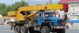
Self-propelled jib cranes, which also include telescopic truck cranes, have historically found the greatest distribution in our country and this is primarily due to the need to mechanize loading and unloading operations. In 1954, the first Ivanovo automobile crane plant in Russia was built, which initially produced cranes with lattice booms, and later with telescopic booms. In addition to the Ivanovo plant, the Galich and Klintsovo manufacturers of mobile lifting equipment with a serial production cycle should be highlighted. The technical characteristics of truck cranes produced by these leading domestic factories correspond to the best foreign analogues. After all, only a boom consisting of several parts that can move relative to each other made it possible to create a mobile lifting mechanism that not only moves freely along modern busy roads, but can also lift loads to a height of more than 100 meters in a vast under-boom space.
Telescopic crane boom
If the first truck cranes were equipped with solid lattice booms on a cable suspension, then all modern machines are equipped exclusively with telescopic booms. The word telescopic implies a product consisting of several parts that can move relative to each other. Everyone is well aware of the compact fishing rod with retractable arms, which are inserted into one another like nesting dolls. When extended, the result is a fairly long flexible structure that can withstand large bending loads. Such fishing rods appeared with the goal of creating the most compact dimensions possible for transportation and at the same time obtaining maximum length in working condition. The booms of automobile cranes have exactly the same tasks, only to solve them we had to go through a number of stages associated with the creation of new technologies, materials, equipment and master the production of not only high-strength steels with a yield strength of at least 550 MPa, but also create the appropriate press equipment for precision bending workpieces, including welding technologies. Leading domestic crane-building enterprises can so far only produce five-section telescopic booms, which in their segment provide quite competitive lifting heights and horizontal reach. The metal structures of the first telescopic booms were assembled from 4 sheets of 10HSND steel, which were knitted in the corners with ordinary angle iron. It turned out hard, the geometry was mediocre, and the strength parameters were far from ideal. But soon they abandoned the corners and began to weld the section boxes with four corner longitudinal welds using semi-automatic welding equipment. To give stability to the side walls, they were reinforced with stiffening ribs and various linings in problem areas.
Photo of the box-shaped boom of the Chelyabinets truck crane KS-45721.
At the next stage, with the advent of powerful presses and the necessary equipment, boxes of individual parts of the arrows began to be assembled from stamped rectangular half-boxes with corner radii and welded on automatic lines. Such structures have less weight and better geometric parameters, especially if imported high-strength steel such as S700 is used.
Photo of a boom assembled from two stamped half-boxes on a 25-ton crane KS-55713-3K-3 “Klintsy”.
The most widespread are arrows with a multifaceted profile and ovoid ones, as they have the best mechanical characteristics.
Photo of the KS-55733 Chelyabinets truck crane with a lifting capacity of 32 tons with an octagonal boom
Photo of a multifaceted arrow made in China.
Classification
According to the general classification, self-propelled jib cranes come in several types. For example, like this:
- Self-propelled - with a lifting element mounted on a platform located on a movable running device.
- Towers. They are rotatable and have a boom attached to a vertical tower.
- Cranes with luffing jib. The machine is of the tower type, but is equipped with a boom that can rise to an almost vertical position.
- Derrick cranes. Rotary units. The difference is a vertical mast with supports at the top and bottom, to which a lifting element is hinged.
- Portal. The boom is located on a portal, which is located above a road or railway.
- Semi-portal, with mounting of the lifting device on the semi-portal.
- Shipborne, located on a watercraft. Designed for unloading/loading a vessel.
- Assembly. They are non-rotating and are installed permanently near the place of work.
Self-propelled vehicles include:
- automotive (the unit is mounted on a vehicle chassis);
- crawler (on a crawler carriage);
- railway (on a platform moving along the railway);
- floating (on a watercraft);
- pneumatic wheel cranes (the trolley has pneumatic wheels);
- rail (on a rail-type running device);
- tractor (on a tractor chassis).
Machines are classified according to the type of drive, which can be:
- single-, multi-engine, individual;
- hydraulic;
- mechanical;
- electrical;
- mixed.
The standards provide for indexing of jib cranes. Their models are provided with indices that display the design features of the units and the main (load capacity, modification) characteristics.
Truck crane boom device
The design of the boom is mainly determined by the technical level of the manufacturing enterprise and the demands of the special equipment market. The first lattice booms were easy to manufacture and did not require special equipment or highly skilled workers, but their length was limited for a number of reasons. They were good for loading/unloading piece goods, because the cable-suspended boom design worked exclusively for compression and, accordingly, had a huge safety factor. To increase the space under the boom directly at the construction site, the boom was extended with special inserts, but this was extremely inconvenient. And in 1974, the first KS-3571 truck cranes with telescopic booms consisting of 2 or 3 parts, which were extended hydraulically using special devices, appeared at the Ivanovo plant. In Russia, the era of telescopic truck cranes has begun, which are used for loading operations, installation of various structures at high altitudes, and can easily maneuver in cramped conditions of a construction site.
The device of a telescopic boom of a truck crane
The diagram below shows the structure of the classic design of a 4-section telescopic boom of a truck crane. In the main section pos. 2 two retractable positions are inserted. 8 and 9, as well as the 10th extension part. The hydraulic cylinder pos. 6 extends the second section, and then the hydraulic cylinder pos. 5 moves the third section relative to the second and at the same time, using a pulley, pushes out the additional extension. This design requires complex hydraulic wiring to supply working fluid to the cylinders and a scheme with one hydraulic cylinder, pos. 6 and a pulley system, in which all sections are pulled out simultaneously.
Diagram of a telescopic 4-section boom of a truck crane Chelyabinsk crane builders went even further and used two hydraulic cylinders located outside on the surface of the main section to extend the second section. This solution greatly simplified the installation, operation and maintenance of boom equipment, although the familiar exterior suffered.
Photo of the KS-65717 “Chelyabinets” truck crane with an original device for extending the second section of the multifaceted boom. Boom sections have upper and lower sliding plates (sliders) pos. 3 and pos. 12, respectively, which provide a minimum coefficient of friction between moving surfaces. Naturally, in addition to the top and bottom, there are side plates. Initially they were made of bronze, then of polyamide with a fairly large area necessary to withstand enormous compressive loads. They are usually lubricated with graphite lubricant, which lingers in special grooves for a long time. If for rectangular profiles the design of sliding plates is simple, then on ovoids they have a curved shape that follows the contour of the arrow. In some designs with insufficiently developed geometry, adjustable sliding plates are still used. To add strength, reinforcing belts (collars) are made on the lower and upper parts of individual sections, which help withstand large local loads during extension; they also do not allow sections to be fully extended, forcing designers to leave a certain seal of about 2 meters, which absorbs the main bending moments when telescoping. On the head there is a bypass block for the cargo rope, which is located along the outlet block pos. 1 hits the cargo winch drum. Lifting hydraulic cylinder pos. 14 at one end rests on the turntable, and its rod through the eyelet pos. 13 is connected to the main section pos. 2. The arrow itself through the heel pos. 15 is also hinged on the turntable.
Ovoid Arrow
Ovoid arrows began to be used quite recently only thanks to the use of the latest calculations using computer programs, which visually presented a completely new technically inaccessible profile.
Ovoid boom profile
The ovoid boom profile was complemented by a rectangular one, which at a certain stage had exhausted its capabilities in terms of the maximum possible load characteristics of a crane of the corresponding class. The designers had to first come up with an algorithm for the necessary calculations, and then use modern computer technology to carry out the calculations. The upper section of the section under load works in tension, the lower in compression, and the side walls bend. For the lower power belt, an arched shape is used that works well for compression. Calculations confirmed the optimal use of boom profile elements similar to an arch. After a long, lengthy search, the designers chose a combined section consisting of half-boxes, an upper rectangular one with rounded corners and a lower one resembling a half-ellipse, which is calculated individually for each arrow. This section of the boom is called ovoid or ovoid, the production of which requires special dies, powerful pressing equipment, special high-strength steels such as Weldox 700 and stronger. To simplify, some factories use bypass technologies to simulate an ovoid profile using multifaceted bending.
Photo of an imitation ovoid multifaceted boom on the KS-54712 “Ivanovets” crane. With the help of ovoid booms, fantastic lifting characteristics of modern truck cranes manufactured by leading foreign and domestic crane factories were obtained.
Photo of the boom with the original ovoid profile on the 60-ton model KS-65721 “Galichanin”
Ovoid
Ovoid is a new term that recently appeared in the technical dictionary under the heading of truck crane booms. The egg-shaped cross-section, which perfectly absorbs all types of loads acting on the telescopic boom, made it possible to make a huge breakthrough in the technical improvement of the world crane construction.
Ovoid photo
In the presented photograph of the cross-section of an ovoid type boom, you can clearly see all its constituent elements and components.
Computer photo of a cross-section of an ovoid arrow
Truck crane "Ivanovets" ovoid
Ivanovo crane builders were among the first to master the technology of producing booms consisting of separate parts with an ovoid cross-section for the entire family of Ivanovets truck cranes.
Truck crane KS-45717K-1R ovoid
The KS-45717K-1R truck crane on the KAMAZ-65115 chassis with a lifting capacity of 25 tons is in high demand on the Russian market, mainly due to the good lifting parameters provided by a four-section telescopic boom with an ovoid profile. The lifting height reaches 31.2 meters with a reach of up to 31m.
Photo KS-45717K-1R “Ivanovets” ovoid
What parameters are used to classify the main types of cranes?
All currently existing types of cranes in construction differ from each other in the following important parameters:
- load capacity;
- type of drive;
- chassis type and characteristics;
- type of arrow;
- number and types of motors.
