In metallurgy and construction, in the production workshop and warehouse, in transport and repair shops, when working with bulk and dangerous goods, overhead cranes are used to move large cargo, non-demountable units and much more. This equipment is designed for intensive work in a wide variety of, sometimes extreme, conditions.
Purpose and design of an overhead crane
An overhead crane is used to move cargo around a workshop, warehouse, or other production facility. A crane bridge with a cargo trolley attached to it moves along the crane tracks laid along the walls, lifting and lowering the load.
According to the bridge design, cranes are divided into:
- Single beam. The bridge consists of one I-beam, at the ends of which end beams with running wheels are installed. In addition to the main cargo trolley, an additional console type can be installed. Cranes of this type are lightweight, but their lifting capacity, as a rule, does not exceed 10 tons.
- Double beam. Structurally, the bridge is composed of two rigid beams with end beams equipped with running wheels. In addition to the main one, the cargo trolley can be equipped with auxiliary lifting mechanisms. This type of crane has a large lifting capacity and is controlled from the cabin or remotely.
Diagram of an overhead crane
Based on the type of fastening, overhead cranes are divided into 2 types:
- Hanging. The load trolley moves along the lower plane of the bridge beam.
- Supporting. The load trolley moves along the upper plane of the support beam. This design provides maximum load capacity.
There are several types of overhead cranes, different from traditional ones, moving along parallel crane tracks:
- Radial. The crane rotates along a ring rail around a support rigidly fixed in the center of the working platform.
- Chordata. Movement is carried out along a ring rail. Due to design features, the area of the ring served by the crane is smaller than that of a radial ring with the same radius of rotation.
- Annular. The crane moves on two ring rails of different diameters. To prevent slipping, the running wheels are made of different diameters.
- Turning. The crane bridge is equal to the diameter of the ring rail along which movement occurs. Unlike the radial crane, there is no central support beam, and the crane can perform loading and unloading operations at any point inside the circle limited by the crane tracks.
In addition to the main working tool, a hook, the crane can be equipped with a grab and a magnetic grip.
Classification
Overhead cranes are used to lift and move large , heavy loads in all areas industrial activity .
The technical characteristics of overhead cranes allow the use of this category of hydraulic lifting equipment both for internal loading and unloading and for external work in any climatic conditions.
The disadvantage GPM bridges is that they are stationary, but the advantage is that they can use the construction height of the building.
Bridge PMGs are divided into 2 large groups : general purpose and special .
Bridge OPI (general industrial design) are equipped with a cargo hook.
Special - equipped with grips that have a highly specialized purpose: grab, magnet, grips for containers. Special lifts appointments are made with a rotating trolley or boom.
A separate group includes metallurgical gas-and-metallic machines intended only for this industry. Such GPMs are equipped with special equipment. grips: foundry, forging, for stripping ingots, etc.
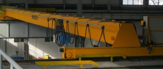
Overhead crane structure
The general structure of an overhead crane consists of a single- or double-girder bridge with a load trolley moving along it. Both the bridge and the bogie are equipped with the necessary electrical equipment and mechanical components. The mechanism is controlled from a suspended cabin or from a remote control when the operator is on the floor of the workshop or outside the work site.
Installation of crane tracks can be carried out either on a free-standing crane trestle or using the floor, columns, and rafter trusses of the workshop.
The photo shows the structure of an overhead crane
Next, we will consider the design of various mechanisms of an overhead crane.
Brake system
The brake system is used to hold the load or control the speed of its movement (drain brake), stop the movement of the crane bridge or cargo trolley (drain brake). Traditionally, lifting mechanisms use closed (closed) brakes that block normal movement. When you press the pedal or handle, the mechanism is released. In an emergency, in the event of a breakdown or stoppage of any crane unit, such a brake mechanism is automatically activated.
Shoe brakes provide smoother and faster braking.
If the cargo trolley moves at a speed not exceeding 32 m/min, there is no need for a braking system, because Friction losses in wheel bearings and when rolling on rails ensure stable deceleration.
This path that the cart has traveled to a complete stop since the start of braking is called the braking path.
Lifting mechanisms
The crane trolley contains a mechanism for lifting and lowering the load. In addition to the main one, one or two auxiliary mechanisms can be used, the lifting capacity of which is 3-10 times less than the lifting capacity of the main one, depending on the class of the crane.
The components of any of them are:
- Drive motor.
- Transmission shafts.
- Gearbox.
- Cargo ropes with a drum for winding.
Diagram of the overhead crane lifting mechanism
To handle loads of more than 80 tons, an additional gearbox or reduction gear is used. To increase the traction force, a chain hoist is used, the most common type of which is a double multiple hoist. Thanks to it, the cable is wound evenly onto the drum from both ends, thereby balancing the load on the drum supports and the entire span of the bridge.
Crane tracks
The purpose of crane tracks is to ensure uniform distribution of the weight of the overhead crane on the foundation and movement of the crane beam along these tracks. For support single girder cranes with low lifting capacity, ordinary railway rails are used as guides. For mechanisms with a lifting capacity of 20 tons or more, special crane rails are used. The basis for them is most often a steel I-beam.
Taking into account the weight of the crane itself and the cargo, as well as the speed of movement along the crane tracks, increased requirements must be applied to the quality of their installation, eliminating the possibility of the crane derailing. To prevent this, the width of the wheels must be greater than the width of the rails used. So, when using cylindrical wheels, their width should be 30 mm or more greater than the width of the rail. For bevel wheels this value must be at least 40 mm.
The rails must be laid with a thermal gap, and the height difference between them must be no more than 2 mm. At large values, a strong shock load on the wheels occurs.
In the case of an overhead overhead crane, the crane track device is a beam, most often an I-beam, fixed to the roof trusses of the room; the load carriage moves along the lower plane of this beam (suspended from it).
Electrical equipment
Special requirements are imposed on the electrical equipment of overhead cranes, including an operating mode in which up to several hundred short-term switching on and off can be performed within an hour, overloads that occur during acceleration and braking of the crane trolley and the crane itself, and changes in travel speeds.
The movement of the bridge and the cargo trolley and manipulation of the load are provided by the main electrical equipment of the overhead crane.
Electrical equipment includes:
- Electric motors. 3 or 4 motors are installed, 2 of which are mounted on the trolley to lift/lower the load and move it along the bridge beam, and 1 or 2 motors ensure the movement of the crane beam along the crane tracks.
- Control equipment (relays, controllers, starters, etc.).
- Electrical protection devices (fuses, circuit breakers, etc.).
- Devices that ensure the operation of the crane's braking system.
Electrical diagram of an overhead crane
Auxiliary electrical equipment includes lighting, cabin heating systems, sound, etc. alarm, etc.
The crane is powered in two ways:
- Trolley line. Most often used with heavy-duty cranes. To ensure safety, the trolley bus must be located at a height of at least 3.5 m from the floor and at least 2.5 meters from the bridge deck. The cargo trolley receives power from its own trolley line mounted on the bridge beam.
- Cable system. This is a flexible electrical cable that uses suspension carriages to prevent damage when the crane or trolley is moved.
- Most often, the first method is used to move the bridge beam, and the second method is used for the cargo trolley.
Two ways to support a crane runway
An I-beam span has upper and lower horizontal chords. Supporting ones are placed on the upper one, and hanging ones are attached under the lower one:
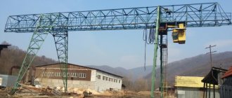
- Support - mounted with wheels on the rails from above. The load-bearing capacity of the support GPM is maximum (up to 500t), but the construction of a crane trestle or supports requires financial costs.
- Suspended - hooked to the lower shelves of the crane runway. This type of support is easy to install and has a low cost. The small lifting capacity (up to 8 tons) is compensated by the low height of the structure, which is why the size of the working area is larger than that of support cranes.
Suspended cranes can be installed on part of the workshop. It is possible to dock cranes (butt lock) and move trolleys from one crane to another.
Device designs vary. They can move translationally or make revolutions around the vertical axis (chordates, radials and rotations) of the PMG.
Why do you need a RB relay?
I made an explanation for the picture below in two forms: in the form of a picture with text, with the need to scroll, and in the form of text itself. Use the form that you find more convenient.
Relays RB, 1RU and 2RU are of the REV type (possibly REV 812, but I don’t know for sure). What is the difference between this type of relay? When voltage appears on its coil, the contacts close or open immediately, without delay, like other types of relays. When the voltage disappears, the contacts return to the previous (normally closed or open) state with a time delay of about 0.8 - 2.5 seconds, which can be adjusted. The fact that the relay operates with a delay can be determined by the appearance of its contacts in the diagram. Let's consider the function of the relay RB. The diagram shows that the RB relay turns on only during descent. And only through a chain of contacts. Let's analyze its operation in the first and second lifting modes. When the crane operator presses the foot pedal, 1T is activated first, through two serial contacts 1T (see 9 washer of the controller) 2B and 1B are switched on, through contacts 1B (6 washer) T is switched on, the brake release magnet will release the brake pads, and finally, through the chain T , 1B, 2B (8 puck) RB will work. When the crane operator releases the pedal, the brake release magnet will turn off immediately, and contactors 1B and 2B (9th washer) will turn off later, when the RB contacts open. Since in these modes the engine works to brake the descending load, it dampens its inertia. The load has a shorter braking distance. Brake pads don't wear out as much.
Now let's consider the transition from the third mode (motor operation in two phases) to the second mode. During this transition, the magnet (through contactors T and 1T) will turn off immediately, and the motor, through contactors 1B and 2B, will briefly turn on for three phases in the back-on braking mode until the RB contacts open.
Now let's look at the circuit of washer 6. There is also a relay contact RB. What is its function? It supplies power to the coil of contactor T, which turns on the magnet, in descent modes in which contactor 1B does not operate (namely in the third and fourth descent modes). The RB in these modes is turned on when all the contactors necessary for engine operation in this mode (2H and 2V in the third mode, 1H and 2H in the fourth mode) are turned on.
Reducers of the movement mechanism.
For hoists and bridges with small load-carrying capacity, mounted gearboxes A-400, B-400, Ts3VK-125 or Ts3VK-160 are usually installed for movement. The drive motor is installed directly on the gearbox and secured via a flange or gear coupling.
For heavy-duty cranes, such a drive scheme is unacceptable due to the bulkiness of the gearboxes, since the dimensions and weight of the gearbox increase disproportionately with the increase in the crane's load-carrying capacity. Both central and independent wheel drive are used. With a central one, there is one electric motor, a gearbox, usually a powerful Ts2-500, and a braking device. With an independent drive, such a set is installed on each wheel, but the engines have less power, and the gearboxes are of a smaller standard size - Ts2-250, Ts2-300, Ts2-350 and Ts2-400. Why Ts2 type gearboxes? In them, a chevron gear is used in the first stage, and a gear with an increased width is used in the second, which makes it possible to transmit high powers without increasing wear on the working surface of the teeth. Depending on the load capacity and width of the bridge span, gearboxes with different gear ratios are used, which ensures different speeds of movement of the bogies.
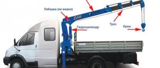
Mast and jib cranes move without rails. Movement occurs on pneumatic wheels or tracks are present.
Slewing crane trolleys usually move along the rope.
If you haven’t found a gearbox in our catalog, call us and we’ll help.
Source
First meeting
Let's start getting acquainted with the electrical circuit of the lifting mechanism from Figure 1. It shows the power circuit of the lifting mechanism (in other words, how power is supplied to the lifting motor). At the very top of the diagram there are three cores of the power cable. The voltage on this cable comes from the so-called linear (the very first in the power supply circuit of the crane mechanisms) contactor (“linear” in the jargon of electricians). The switch allows you to disconnect the power circuit (for example, if there is a fault in it), as well as ring it separately from other circuits.
Below it are the coils of the maximum current relay (electricians call them maximum current). These coils have few turns and are made of thick conductor to withstand the large current passing through them. There is one such coil in the photo, but on the tap all three coils are combined into a single mechanism. When the current in at least one of the coils exceeds the permissible limit, this mechanism is triggered and opens the contact (common contact for all three coils), which turns off the power supply to the lifting mechanism. Below the coils, the diagram shows two wires extending to the side. They go to the LV contactor circuit. We will analyze this circuit a little later. We will also look at the operation of power contactors and resistors a little lower.
How the lift works
What do all four lift modes have in common? The contactors of the release magnet T and 1T are turned on, the magnet fully depresses the brake pads. Power contactors 1B and 2B are turned on, which rotate the motor. The acceleration contactor P is turned on. This is a contactor (see figure) that provides minimal acceleration (the first acceleration stage) of the motor. Notice how voltage is applied to these contactors. First, the 7 washer is closed, including 2B. From the 7th washer, the voltage goes to the 2nd washer (1V), and then to the 3rd washer (P). When switching to the second, third and fourth modes, acceleration contactors 1U, 2U, and, in the fourth mode, 3U and 4U are turned on sequentially.
Operating circuit
Advice. Scrolling the page from the description to the diagram is inconvenient. If you are reading this page on a personal computer, open the diagram image in a separate tab (cursor on the image and right mouse button). And if the white background annoys you, open the same image, but with a green background.
The LV contactor turns on and off the so-called operating circuit of the lifting mechanism. It is shown in the diagram. What is an operational chain? This is the circuit that supplies voltage to the contactor coils. Constant voltage 220 Volts (there are coils and 110 Volts, therefore, the corresponding voltage will be supplied to them). Next, other mechanisms of the crane will be considered: movement, cart travel, turning. Each of them has a LV relay. Look at the picture. Find the key. Here it is, the main contact of the LV contactor. More precisely, two serial contacts, in case one of them “sticks” (that is, the movable contact is welded to the stationary one due to the high current). Now remember that the LV contactor will turn off if relays 1RU and 2RU (both) turn off. Under what conditions will they both turn off? When voltage stops flowing into the operating circuit, for example, because one of the fuses blows: 1P or 2P. If there is no voltage in the operating circuit, there is no point in turning it on. It probably now also becomes clear to you why the first contact of the controller turns on only in the zero position. When voltage is initially applied to the operating circuit (for example, after turning off the voltage), the mechanism should not immediately begin to move, no matter what position the controller lever is in. Therefore, until the crane operator sets the controller lever to zero, voltage will not enter the operating circuit.
The most common types of mechanisms:
Bridge, gantry, cantilever, port, railway and tower lifting machines move on rails. The traction for this type of movement is wheels, rope or chain. To drive the wheels, the entire movement mechanism is mounted rigidly on the crane frame. For rope or chain movement, the mechanism is installed outside the crane. Wheel movement is in turn divided into single-rail and double-rail. It is worth noting that single-rail construction is extremely rare - these are jib cranes, some types of trolleys and hoists.
Flexible cables
The crane hoist motor we are studying is located on a turntable, which in turn is located on a cart that moves along the crane's bridge beam. The remaining elements shown in Figure 1 are located on the bridge beam (“on the bridge,” as electricians say). Therefore, the engine is connected to them by flexible cables suspended on a cable. As the cart moves across the bridge, the cables follow it. Since they are subject to bending during the operation of the crane, the cores of these cables tend to break, which often causes the crane to malfunction.