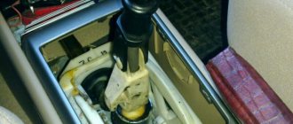
To adjust the lifting of loads on cranes, shoe brakes of the TKG series are most often used. The brake pulley is mounted strictly vertically so that the axis of rotation of the pulley and the base is in a horizontal plane. It is regularly necessary to check and adjust the brakes so that both pads are compressed on the drum without play, and both pads are separated from the drum. In this case, adjustment is required - The operation of the TKG, TKT, TKP brake is based on the use of friction force arising from the braking force of the brake pads with the shaft being braked. The TKG brake pads are located diametrically relative to the brake pulley and create equal and opposite pressure on the brake pulley. When the hydraulic pusher rod moves upward, the post-lever rotates, compressing the spring, and the brake struts, together with the brake pads, move away from the brake pulley, thereby releasing the brake. By tightening the nuts on the rod (horizontal adjusting rod) and the balancing stop, ensure that both shoes move evenly away from the drum.
Synchronous vomittron. Riding a crane without brakes.
When the TKG brake pusher for the crane is not working, the system is braked under the action of the spring (3) adjusted according to the calculated braking torque. When the electro-hydraulic pusher is turned on, the lever (2) rises to the upper position as shown in the figure above. The action of the spring is overcome, the racks (4 and 6) diverge. The stroke of the lever system is limited by stops, and they are adjusted by adjusting screws (8). The pads move away from the pulley by an amount S (indicated in the table above), the system is released. After the hydraulic pusher is turned off under the action of the spring (3), the system of levers (2, 4, 6) returns to its original state. To ensure their correct fit to it, adjusting screws (7) are used. Following the crane rider, the passengers of the overhead crane posted their video.
Application area
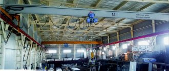
Crane brakes are used everywhere. They are found on construction sites where heavy lifting work must be performed.
Brakes are used:
- in ports;
- at metallurgical plants;
- at shipyards;
- in mining;
- at nuclear power plants.
Such special equipment can be used by any large production, since it saves time, physical effort, and allows you to fulfill the plan faster. The equipment is supplemented with lifting mechanisms, as well as electric motors. They control the operation and allow automation of the braking system. Fast response guaranteed.
Tower crane s250 load brake replacement.
When the trolley speed is 32 m/min or less, brakes do not need to be installed in the moving mechanisms. In this case, the energy reserve is small and the friction in the bearings and on the rails is enough for the mechanism to stop at the permissible braking distance (p. Depending on the braking force, the descending load, crane bridge or trolley will continue to move with a gradually decreasing speed until it stops completely. Path traversed by the mechanism from the beginning of braking to a complete stop is called the braking path. The brake coil burned out, and the crane was working on a jammed brake.
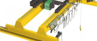
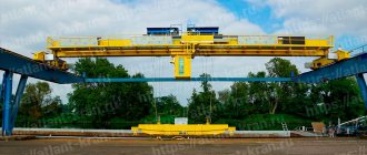
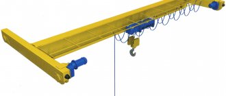
Single girder overhead crane: devices, diagram
Electrical diagrams of overhead cranes
Electrical diagrams can be schematic or elemental, wiring or labeled. Schematic diagrams reflect the interaction of elements of electrical equipment, indicate the sequence of power circuits and devices
management. It is convenient to use schematic diagrams for repairs and adjustments. The equipment in them is simply and clearly divided into separate independent circuits, and they are easy to remember. Electrical circuits in schematic diagrams are divided into power circuits, depicted by thick lines, and control circuits, depicted by thin lines. Wiring or labeled diagrams, in contrast to schematic diagrams, depict the electrical wiring of the crane and the relative position of electrical equipment.
Electrical protection. As noted above, protective panels PZKB-160 and PZKN-150 are used as electrical protection. Some factories produce their own protective panels. Regardless of this, each such assembly is a complete panel on which are mounted: a three-pole switch, control circuit fuses, a three-pole contactor, an overcurrent relay, contact terminals for control circuits and line wires, a start button and a control circuit transformer.
Promotional offers based on your interests:
Let's consider the electrical circuit of the PZKB-160 protective panel (Fig. 36). The control circuit is shown with thin lines, the power circuit with thick lines. An explanation of the power circuit diagram will be given below. At this moment, consider a control circuit diagram without elements located to the right of the dotted line connecting the points.
From the above diagram it is clear that voltage supply to the contactor coil L is possible after pressing the KB button, when the handles of all controllers KP, KT, KM are set to the zero position, the emergency switch AB is turned on, the hatch contact KL, the cabin door contact KD are closed, the key is turned on - brand KM and the contacts of the maximum relay MP are closed. After turning on the linear contactor L, its block contacts L close in the control circuit, shunting the KV button. This creates a closed circuit: wire L1, coil L, contacts MP, KM, KD, KL, AB, KM, KVMN, KVTN, KT, KP, block contact L, wire L2.
When the controllers are brought from the zero position into the operating circuit, it does not open, since the current does not pass through the zero contacts of the controllers, but through the circuit with block contact L, and the linear contactor coil is powered through a parallel circuit.
Rice. 1. Electrical diagram of crane protection.
The second closed circuit is formed when the VM or NM contactors are turned on, which is carried out by the contacts of the K11M or K9M movement controller. In this case, the mutual interlocking contacts NM or VM are opened in the circuit, protecting against the simultaneous activation of these contactors.
When the limit switches of the bridge movement mechanism KVMN, KVMV are triggered, the linear contactor L does not disappear, but only the direction contactor VM or NM is turned off and the movement mechanism stops. The line contactor will switch off when any other limit switch or safety device is activated. In this case, the L contacts in the power circuit are disconnected and the mechanisms are de-energized. To start the controller handles, you must return to the zero position and press the KV button.
Reversing. For reversing, i.e. To change the direction of rotation of motors, contactors or reversible magnetic starters are used. In Fig. 37, a shows a diagram of a reversible contactor panel, and in Fig. 2 - diagram of a reversible magnetic starter. To reverse motors, two two-pole contactors are sufficient. When you turn the controller handle, voltage is applied to the control circuit and the coil is turned on, which closes the upper pair of contacts of lines 1-11 and 3-12. In this case, the engine rotates in the Forward direction. When voltage is applied to the control circuit, which corresponds to turning the controller in the opposite direction, the I coil and the lower pair of power contacts are turned on, closing lines 1-12 and 3-11. In this case, the motor rotates in the Reverse direction.
Rice. 2. Reversing scheme. a - using a contactor panel: b - using magnetic starters.
The reversible magnetic starter consists of two three-pole starters that have mutual mechanical and electrical interlocking. When the contacts of the universal switch VII are closed, coil B of the starter is turned on and the corresponding power contacts B close lines 1-12, 2-13, 3-11. The motor rotates in one direction. When coil H is turned on, lines 1-11, 2-13, 3-12 are closed, which causes a change in the phase order of the electric motor, so it rotates in the opposite direction.
Electric drive control. As mentioned above, starting resistors are used to soften the starting characteristics of mechanisms.
Starting resistors are controlled: – in a direct way, in which the resistance circuits are connected directly to the terminals of the controller installed in the crane cabin; – remotely, when the resistor circuits are switched on by the contactors of the magnetic panel, controlled by a command controller installed in the cabin.
In Fig. Figure 3 shows a diagram of the direct control of the electric drive of the crane. The diagram shows a controller KM type KKT-62A, two starting resistors PS1 and PS2 type NF-2A, two motors Ml and MZ and two electric hydraulic brake pushers M2, M4. At the first position of the controller, the rotor windings are closed to a full set of resistances, at the second position the controller contacts are turned on, and part of the resistor is turned off. The engine switches to a more rigid characteristic, its rotation speed increases, etc. At the fifth position of the controller, all resistors are turned off, the rotor windings are short-circuited, the engines operate at natural characteristics, where the speed reaches its highest value.
As an example of a remote method for regulating the start of an electric motor with a wound rotor in Fig. Figure 4 shows an electrical diagram for controlling the movement mechanism. The start of the electric motor is controlled and the rotation speed is regulated in this case using a KK controller type KKT-61A. However, here the controller works in the control circuit as a command controller, and the ballast resistors are switched using a magnetic controller. When switch B is turned on, voltage is supplied through the coils of the maximum current relay PT1 and PT2 to the fixed contacts of contactors K1 and K2. At the zero position of the command controller KK, the pull-in coil of the intermediate relay P1 receives power through the circuit: wire 010, closed contacts KK, UP1, RT1, RT2, UP1, wire 037. Relay P1 closes its contacts in circuits 020-023 and 025-036.
Rice. 3. Direct control diagram for the electric drive of the crane.
Rice. 4. Scheme for controlling the electric drive remotely. a - power circuit; b - control circuit.
When the handle of the command controller KK is installed in the first position of the Forward position, contactor K1 closes - This turns on the electric motors Ml, MZ, M5 and M7 of the movement mechanism and M2, M4, Mb, M8 of the hydraulic brake pushers. When the command controller is moved to the second position, the contactor coil KB receives power, which closes the starting resistor sections in the rotor circuits of the travel motors. Further rotation of the controller handle sequentially turns on the coils of contactors K7, K8 and K9. At the last position, all resistances are bypassed, i.e. The rotors of electric motors are short-circuited, so the motors operate at natural characteristics. When the handle of the command controller KK is moved to the Backward side, the contactor coil K2 is turned on in the first position. As a result of changing the phase connection order, the motors rotate in the opposite direction.
When each of the relays PT1 and PT2 is triggered at any position of the controller, the breaking contact of one of these relays opens, coil P1 will be de-energized and will open its contacts in the circuit of coils K1, K2. The power circuit will be open and the tap will stop. Further start-up of the electric drive will become possible only after the controller handle returns to the zero position.
Features of control of a magnetic controller type TSAZ-160. For magnetic controllers TSA and KS, the first and second positions of the controller are used for lowering loads at a reduced speed above 50% of the nominal one. In this case, in the first descent position it is possible to work only with a nominal load. To lower heavy loads in the first and second positions, you must turn on the low pressure pedal. Then in the first position the relay 1RU, 2RU is turned on. When the pedal is pressed, the back-off contactor P, contactor B, start contactor gearbox, brake contactor T and blocking relay RB will turn on.
In the second position of the command controller, the back-off contactor P is switched off. In the first and second positions, the engine operates in reverse mode.
A load weighing less than 50% of the nominal weight will not be lowered in the first and second positions of the command controller. Its lowering is possible only in the third position of the controller. In the third position of the command controller, contactors H and O are turned on. This causes the motor to switch on to single-phase braking mode. Contactors I and O turn on the blocking relay RB, which turns on the contactor T - the mechanism is released. The circuit of contactors B and KP is broken by block contacts I and O. In the same position, contactors 1U, 2U are switched on in series. Contactor 2U breaks the circuit of relay 1RU, which in turn turns on contactors ZU and 4U with a time delay, i.e. starting resistors are turned on.
Rice. 5. Schematic diagram of an electric lifting drive with a magnetic controller TSAZ-160. a - power circuit; b - control circuit; M engine; TM—brake magnet; T—brake magnet contactor; KP - start contactor; B, N - motor rotation direction contactors; O - single-phase braking contactor; P - back-off contactor; 1U-4U - acceleration contactors; MP - maximum current relay; RB - blocking relay; 1RU, 2RU - acceleration relay; KVV, KVN - limit switches; BC - selenium rectifier; R1-R2 - additional resistors; NP - foot pedal; P - switch; 1P, 2P - fuses.
In the fourth position of the controller, contactor O is switched off. Acceleration contactors 1U - 4U are turned on, all resistors are removed. Contactors I, KP, T and blocking relay RB are switched on. The load is lowered at a supersynchronous engine speed.
When the controller handle is slowly moved from the third position to the second and first, the light load will inevitably go up in this case, since contactor B will turn on, which in turn turns on the gearbox, then T and RB. In the first position it will additionally turn on. This scheme allows the crane operator to select the position of the command controller corresponding to the load.
Promotional offers:
Read more: Recommended changes in electrical circuits of cranes
TO
Category: – Electrical equipment
Home → Directory → Articles → Forum
Shoe brake TKG-300-SU-U2.
Lifting mechanisms for cranes transporting hot metal, explosives and toxic substances and acids must have two brakes that act independently of each other. When the engine is switched off, the brake is automatically closed, causing the load to hang in the air. Closed brakes are also installed on the crane's moving mechanisms. By absorbing the inertia of moving parts, they thereby help shorten the path of their movement after stopping the engine. You can visit our website: Or contact us by mail: [email protected]
Description: The TKG-300 brake is installed on the DEK-251 crawler crane on the load lifting winch. You can buy TKG brakes of various modifications and designs at. Manufacturer prices. Guarantee. We will organize delivery of the TKG-300 brake.
Is repair possible?
In 90% of cases, the restoration of built-in factory brakes is short-term. In a couple of months or, at most, six months, you will have to do repairs again. It’s easier to take new crane brakes and install them according to all standards. Then the equipment will last longer, this will not contradict safety standards. Installation should only be trusted by experienced professionals.
Poorly selected parts will impair the performance of the loading equipment. There is a chance that she will not stop at the right time. This may lead to an accident. It is better to buy an original spare part from the manufacturer, and not an analogue for replacement. The grooves for installation may be different or the part will not be the same in functionality, which will worsen the operation of the crane.
Pre-defense of bachelor Yulia Skorchenko.
The final stage is the rotation of the rod until it comes into contact with the magnetic core. At this point, the brake pads should be in their normal operating position. We present the report of bachelor Yulia Skorchenko, which was made on May 16 at the Department of Mining Machines and Engineering as part of the scientific and technical conference “Student Science Week” in the “Mining Machines” section. Bachelor Yulia Skorchenko defended her thesis on the topic “Development of a technical design for a shoe brake for a mine hoisting machine MPMN-5×4.” The scientific supervisor of the work is Professor Zabolotny Konstantin Sergeevich.