- home
- Media center
- Articles
- Steering control of caterpillar tractor T: design features and device
Menu
- News
- Articles
- Video materials
- Photo materials
- Publication in the media
- 3D tour
24.06.2020
The steering system of tracked vehicles differs in design and principle of operation from the mechanism of wheeled vehicles. Directing a tracked vehicle along a given path, maneuvering, and controlling power transmission mechanisms and equipment is ensured using the steering control of the T-150 tractor and other models. With skillful operation of the vehicle and sufficient practical skills, a heavy machine on tracks can easily maneuver to perform special work. The mechanism has a simple design and, with proper maintenance, is reliable in operation.
With the help of the control system, gears are switched on the go, sharp braking in unforeseen cases, holding a multi-ton machine on a slope, and also turns in different ways along an arc:
- with constant radius;
- with a variable radius depending on the rolling resistance of the tracks (smooth maneuvering);
- with a minimum radius due to partial (full) fixation of the left or right side brake with the friction clutch turned off.
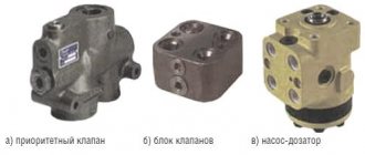
Types, design and principle of operation of the metering pump
The metering pumps currently in use have a fundamentally identical design. The pump consists of three units:
- Follow-up hydraulic distributor (distribution block);
- Feedback hydraulic motor (pumping unit);
- Valve block.
All units are interlocked into a single compact structure, which is installed at the end of the steering shaft and is connected through pipelines to other parts of the system (pump and hydraulic cylinders). Metering pumps differ in the type and design of individual units - the distribution block and the hydraulic motor.
The follow-up hydraulic valve is of the spool type, built on the basis of a hollow spool (or two spools at once) with grooves and channels, which has a direct connection to the steering wheel shaft (therefore, the input signal of the distributor is steering deflection). The spool can rotate around its longitudinal axis, which ensures the distribution of the flow of working fluid coming from the supply pump. In the middle position of the steering wheel, the spool is located in such a way that the oil from the power pump is drained through the valve block into the oil tank - in this case, the wheels are installed in the forward direction and no rotation occurs. When the steering wheel is deflected to one side or the other, the spool rotates and the fluid flow flows to the pumping unit, and from there to the actuating hydraulic cylinders.
The pumping unit can be of two types:
- Axial piston;
- Planetary (gerotor).
The axial piston hydraulic motor is made on the basis of spring-loaded ball valves located on both sides of the cam washer. The cam washer has recesses for the pistons, and it itself is connected to the spool. Turning the spool causes the washer to rotate, it moves and the balls fall into its holes - this is how the cavity behind the ball is filled with working fluid. With further rotation of the washer, the balls rise and close the cavities, which leads to the supply of the oil they contain to the valves and further to the actuating hydraulic cylinders.
The planetary hydraulic motor is made on the basis of a system consisting of a cage (ring, fixed gear) with rollers and a satellite (star) rotating inside it, which is connected to the spool through an eccentric. The satellite is installed so that between it and the holder there are several closed cavities of varying volumes. When the satellite rotates, the cavities change their volume: some of them increase, some decrease. Above all the cavities there are channels through which, depending on the position of the spool, the working fluid is supplied or removed. In the neutral position of the spool, the working fluid passes through the cavities and valves without exerting any influence on them, and is drained into the tank. When the steering wheel is turned, the spool and valves are set in such a position that oil enters the cavities at the moment their volume increases, and when the volume subsequently decreases, it enters the actuating hydraulic cylinders.
Purpose and steering device
Structurally, the steering elements of a caterpillar tractor are arranged in the cabin and include a steering wheel, gear levers, special brake pedals, clutch pedals, etc. The system also includes measuring and signaling devices.
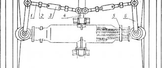
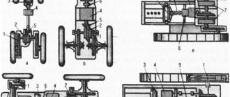
Schematic representation of a classic tractor steering mechanism on tracks.
Essential elements
- speed selection levers;
- pedal for activating the brake;
- rods designed to control the sides;
- shaft controlled by levers;
- tension springs;
- side control levers (right);
- side control levers (left);
- traction for influencing the brake drive;
- a pipe with leads laid inside;
- starboard brake drums;
- left side brake drums;
- hydraulic panel;
- lever that controls the pressure reduction valve on the left side;
- gear box;
- hydraulic distributors;
- right and left hydraulic distributor lever;
- lever that controls the right side pressure drop valve.
The brake pedal is rigidly connected to the brake band installed on the corresponding side. The steering wheel, using a rod and an intermediate system, is connected to levers designed to control the left-right track. The selection of tractor speeds is ensured using special levers that are mounted on the steering column. Both speed selection levers are connected by rods to distributors installed on the corresponding sides.
Important components that provide adjustment of the speed of movement of the caterpillar on each side of the vehicle are steering couplings. The devices are structurally a dry type multi-plate clutch. To change the trajectory of the tractor, the right or left clutch is disengaged. The clutch is deactivated using a lever acting through the pressure plate on the springs. As a result of spring compression, the clutch discs move away from each other, disconnecting the shaft through which torque is transmitted.
In the absence of effort, the caterpillar begins to lag behind the other one, which receives a flow of power. As a result, the tractor begins to turn towards the side with the clutch disconnected. To ensure a sharp turn, it is necessary, in addition to disabling the clutch, to act on the brake pedal. The braking band will tighten the driven drum and abruptly stop the movement of the braked track.
To smoothly disengage the left or right clutch, the tractor driver has to apply a force, the value of which is in the range of 120 - 150 N. To reduce the applied physical force, a hydraulic booster is installed in the control system of the crawler tractor. The unit is mounted between the rod and the control lever to increase comfort in operating a multi-ton machine. Thanks to the hydraulic booster, to disengage the clutch it is enough to apply a force of up to 20 N to the lever.
Issues of selection, replacement and maintenance of a metering pump
During the operation of the HPS, high pressures operate in the metering pump, and the parts of this unit are also subject to intense mechanical loads - all this leads to wear of components, increased gaps and breakdown of the unit as a whole. A malfunction of the LP is indicated by the lack of reaction from the steering wheel when turning it and, on the contrary, spontaneous rotation of the steering wheel, as well as incorrect operation of the steering. If these malfunctions occur, you should diagnose the steering parts and the metering pump. This work must be performed in accordance with the repair and maintenance instructions for the tractor/self-propelled machine, or in accordance with the instructions for a separate unit.
If a malfunction of the metering pump is detected, repairs should be carried out using repair kits. The most common problem with ND is wear and damage to sealing elements - rubber rings, seals and gaskets. Damage also occurs in bearings, shafts, hydraulic motor plates, etc. All these parts and seals are now offered as repair kits, which reduces the cost of repair work.
If the pump cannot be repaired, you must buy a new unit. A replacement metering pump should be of the same type and model as was previously installed. If necessary, you can use an analogue, but it must have the same performance (or at least no less performance) and a suitable drive design. Additionally, a set of fasteners and related parts may be required to perform installation work. Installation and commissioning of a new metering pump is carried out in accordance with the instructions. With the correct selection and replacement of the LP, the tractor steering will work reliably and efficiently under any operating conditions.
A turn with a fixed radius can be carried out at the request of the tractor driver, reducing, maintaining or increasing the average speed of the straight-line movement of the tractor, depending on the aggregation conditions. Turning with an increase in the average speed of the tractor is possible only when the engine is not fully loaded during straight-line movement.
To reduce the average speed when turning the tractor, move the lever of the side towards which the turn is taking place (towards the lagging side); to turn the tractor at a constant average speed, simultaneously move the levers in opposite directions by one step (only when the tractor is operating in second and third gears); To increase the average speed when turning the tractor, the running side lever is moved away from you.
To turn the tractor with a free (non-fixed) radius, turn the steering wheel, thereby partially or completely disengaging the hydraulic clutch of the side towards which the turn is being made. The steering wheel is connected to a leash, which, when the wheel turns in one direction or another, acts on one of the levers. The lever, through a system of connecting rods, acts on the valve spool of the smooth pressure reduction valve of the corresponding side of the gearbox.
A certain position of the steering wheel corresponds to its pressure in the hydraulic clutch and a certain torque transmitted by it. The clutch is completely disengaged when the steering wheel is turned by 42°. This and the initial position of the steering wheel are marked by clicking a lock located at the top of the steering column. With further rotation of the steering wheel, the shaft, acting through the intermediate lever on the rod, tightens the brake band around the brake drum of the secondary shaft. The tractor turns sharply, and when the brake drum comes to a complete stop, it turns around the stopped track with a radius equal to half the tractor track width. The steering wheel and the entire rod system return to their original position under the action of springs.
Rice. 1. Control diagram of the T-150 tractor: 1 - gear shift levers, 2 - brake pedal, 3 - side control rods, 4 - lever control shaft, 5 - release springs, 6, 7 - right and left side levers, 8 - rod brake drive, 9 — pipe with levers, 10 — starboard brake, 11 — left side brake, 12 — hydraulic panel, 13 — left side pressure reduction valve control lever, 14 — gearbox, 15 — hydraulic valves, 16 — right hydraulic distributor lever, 17 — starboard pressure reduction valve control lever
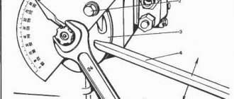
To prevent the hydraulic clutches on both sides from turning off at the same time, there is a locking mechanism in the form of three balls, which are freely placed in the hole in the driver between the recesses in the levers. When you turn the steering wheel, the leash rests on one of the levers and moves with it. The balls are forced out by a fixed lever and stop the leash with a movable lever. When the steering wheel is returned to its original position, the balls enter the recess of the fixed lever and release the movable lever from the leash. If you turn the steering wheel in the other direction, the leash will correspondingly move another lever, which will also lock with the leash, and the previously movable lever will be stationary.
Rice. 2. Control of a caterpillar tractor: a - device, b - position of the locking balls when turning the steering wheel to the left, c - steering column; 1 — mountain brake latch, 2 — mountain brake pedal, 3 — latch rod, 4 — rods, 5 — gear indicator, 6 — gear shift levers, 7 — steering wheel, 8 — lock, 9 — steering column, 10 — intermediate shaft levers, 11, 16, 18 — levers, 12, 13, 14, 15, 17 — connecting rods, 19 — leash, 20 — ball, 21 — steering shaft; arrows indicate the direction of movement of the steering wheel, rods and levers when turning the tractor
For emergency braking of the tractor and holding it on a slope, use the right mountain brake pedal, which is connected by rods and levers to the brake drum band of the secondary shaft of the gearbox. The pedal is secured in the braked state with a latch, which, if necessary, is pulled over the hook of the mountain brake pedal. The pedal is returned to its initial position by a special spring.
Maintenance of the control mechanism. The precise operation of the control mechanism depends on the timely lubrication of the rubbing surfaces and the correct adjustment of the brake drive, control of the smooth pressure reduction valves and hydraulic valves.
Check the tightness of threaded connections every shift and tighten them if necessary.
After 240 hours of work, clean the oilers and pump grease “C” into the rod ends, into the bushings and shafts of the steering (control) levers until it appears in the gaps.
Adjustments to the tractor control mechanism are carried out only when disassembling the tractor and when replacing control parts.
To adjust the brake drive, the brake pedal is set to its highest position until the rubber stop touches the cabin floor. By changing the length of the rod, set the lever to a vertical position. Then, by adjusting the length of the rods, the platform and fingers of the shaft levers are aligned. In this case, the rod links should be in a straight line, and the brake bands should be released.
To adjust the control of the smooth pressure reduction valves, remove the rods and return springs of the rods. The steering wheel is installed in the second fixed position and, by rotating the traction control clutch, the platform and fingers of the shaft levers are brought into contact (aligned). Return the steering wheel to its original position and install the rods and return springs of the rods. Using adjusting rod couplings, a gap (0.5-1 mm) is established between the levers and the driver.
To adjust the control of the hydraulic distributors, move the distributor spool levers to the first gear position, and by changing the length of the rods, place the levers connected to the upper ends of the rods in a horizontal position. Using adjusting rods 4, control levers 6 are installed so that there is a gap between them and the pointer stops 5 in first and fourth gears.