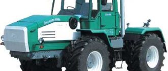
Without exaggeration, the legendary T-25 tractor is one of those few agricultural machines whose popularity is practically not affected by the presence of more technologically advanced and advanced models on the market. This is due not only to the highest reliability of the domestic tractor, but also to its versatility, simplicity of design, maneuverability and endurance.
The T-25 Vladimirets tractor has a number of design features. These include a high-quality multi-speed gearbox, spring suspension and a universal linkage system located at the rear of the tractor. The supporting area of the lugs used is from 25 to 35%, and their height is from 3.5 to 4.5 cm. This feature significantly improves the quality of work of the T-25 tractor in the garden.
Many modern tractors are not able to work on sticky soil due to the small width of their wheels. In contrast, the T-25 tractor can be equipped with dual wheels or wide-profile tires, which significantly improves its traction on wet ground. If necessary, the farmer can deflate the tires a little, which will positively affect his stability on loose soil.
Experts consider Vladimirets’s biggest advantage to be his ability to use a front-end loader for work. The speed range when working with a tractor is 1.37–30.28 km/h. The radius required to turn the unit must exceed 3.5 m - this allows the agricultural machine to be successfully used in small areas, as well as in greenhouses and greenhouses.
Tractor engine T-25
The design of Vladimirets provides for a reliable and durable diesel engine of the D 120 brand. A high-quality forced air cooling system is responsible for the safe operation of the engine under high loads.
The T-25 engine consists of 2 cylinders and runs 2 strokes. The rotation speed is 1800 rpm, which is more than enough for use with a tractor of almost all types of attachments. To start the engine, the tractor is equipped with an electric starter.
The factory weight of the motor is approximately 300 kg and may vary depending on the parts farmers use to repair the engine. The initial stroke of the piston is quite large - approximately 10.5 cm.
An important advantage of the Vladimirets engine is its modest oil consumption, which ranges from 0.3 to 0.5 per unit of fuel consumed.
Transmission Vladimirets
The T-25 tractor is equipped with a manual transmission, capable of operating in 14 speed modes. Two of the tractor's rear gears operate at a slow speed, which is necessary for the use of seeders, fertilizer distribution equipment and other structures with the tractor. The gearbox is equipped with cross shafts, which significantly extend the service life of the T-25 tractor transmission.
The Vladimirets clutch is presented in the form of a dry single-disc mechanism, which is constantly closed.
Tractor chassis
The T-25 Vladimirets tractor is a unit in which the rear axle is the drive. In the front part of the balancer included in the design, bosses are provided, inside of which special high-strength bushings made of hardened steel are cemented.
The ends of the balancer provided in the design of the tractor are equipped with special cuts in which the steering knuckles are fixed using tightening bolts. Each knuckle has 4 holes, necessary for adjusting the track width. By inserting a pin into one of the holes, the track changes, and with it, the ability to use different attachments.
A sealed, dense rubber chamber with an air valve is placed on the wheel rim. In the inner part of the rim there are 6 posts that hold the disc. The latter is fixed to the flanges of the rear wheel axles. By rotating the disc in relation to the axle flange, it becomes possible to adjust the rear track in the range from 120 to 150 cm.
The optimal tire pressure for the T-25 tractor to perform agricultural work is considered to be in the range from 0.8 to 0.9 kg/cm2. To transport cargo, the pressure must be increased to 1.2 kg/cm2.
Depending on the modification, the T-25 tractor may have all-wheel drive - in most cases, such models are used to work in the most difficult operating conditions.
content .. 81 82 85 ..SIDE (FINAL) TRANSMISSIONS OF TRACTOR T-25
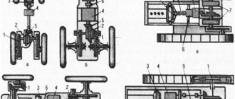
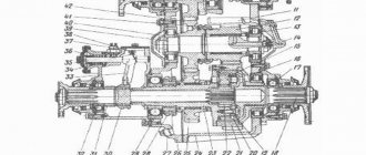
Final drives transmit torque from the differential side gears to the rear drive wheels of the tractor. The tractor is equipped with two identical final drives, attached together with the brake hoses to the side surfaces of the main gear housing.
The cast iron housing 13 (Fig. 61) of the final drive forms part of the supporting frame of the tractor. In the upper flange of the housing there are threaded holes for the final drive mounting pins and two holes for pins 21. These pins are pressed into the housing flange and freely fit into the holes of the outer flange of the brake hose 20 and determine the position of the final drive housing during various adjustments of the tractor.
The upper bores of the housing include the outer rings of two radial ball bearings, in which the drive gear 16 of the final drive rotates. The outer bearing 15 is closed by a solid cover 14, and the inner one by a seal housing 18. Self-clamping oil seal 19 prevents oil leakage from the final drive into the brake hose. To increase the reliability of the seal, bearing 17 has a protective washer on the outside. In addition, to relieve the oil seal from increased oil pressure, four through drillings are made in the housing flange, and special non-forgings are made into the oil seal housings, through which oil is drained from the oil seal housing back into the final drive housing.
The inner rings of bearings 15 and 17 are pressed onto the drive gear shaft until it stops against the gear, which is integral with the shaft. In the middle part of the drive gear shaft there are two special keyways for the brake pulley keys. The inner end of the shaft has splines cut for connection to the differential side gear.
The final drive drive gear is in constant engagement with the driven gear 1, located on the splines of the rear wheel axle 7. The axle is made integral with the flange, to which the disk of the rear drive wheel is attached with special bolts with conical heads.
The rear wheel axle is mounted in the lower bores of the housing on two tapered roller bearings. The inner ring of bearing 2 is pressed onto the cylindrical surface of the wheel axle until it touches the shoulder. Next, driven gear 1, spacer ring 29, inner ring of bevel bearing are put on the axle
stud 23 and washer 26. The set of parts on the axle is tightened with a castle nut 25.
The outer ring of the bearing 23 fits into the cup 27 until it touches the collar. The cup with the bearing is closed with a stamped cover 24. Under the flange of the cup there are thin steel spacers 28, which regulate the axial clearance in the tapered bearings. A sealing rubber ring 22 is placed in the annular groove of the glass.
To prevent oil leakage from the final drives and protect them from dirt and water, an end-face seal with metal sealing rings is provided at the point where the wheel axle exits the final drive. The thrust ring 5 is placed on the axle until it touches the flange. The pressure ring 11 is pressed against the end surface of the thrust ring by four springs 8. The pressure springs are inserted into the drillings of the pressure ring and cover 12. Two pins are also pressed into the cover, which freely fit into the holes of the pressure ring and keep it from turning. A rubber diaphragm 4 and a protective ring 3 are attached to the cover with two bolts. With an internal hole, the diaphragm is mounted on the cylindrical surface of the pressure ring and pressed tightly to its flange with ring 9.
When assembling the final drive, the cover, along with the diaphragm, springs, protective and pressure rings, is installed on the wheel axle before the inner ring of bearing 2 is pressed onto it and secured to the final drive housing with four bolts. The bolts are screwed through two large holes in the wheel axle flange and secured with a locking plate.
In the assembled final drive, the thrust ring 5 rotates along with the axle, and the springs 8 press the stationary pressure ring against it. The end rubbing surfaces of the rings are cemented, calcined to high hardness and carefully ground to each other. In progress
During operation, they are constantly pressed, which ensures a reliable seal of the final drive. The protective ring 3 and the inner ring 10 welded to the axle protect the seal parts from damage.
At the bottom of the final drive housing there is a rectangular hatch through which the driven gear is mounted. The hatch is closed with a pan 30. For filling, draining and monitoring the oil level, holes are provided in the final drive housing, closed with conical plugs. The holes are placed so that in each position of the final drive when readjusting the tractor, convenient refueling, draining of oil and control of its level are ensured.
The outer flange of the drive wheel axle has a machined bore and two threaded holes for fastening the drive of working machines that require synchronous power take-off. The threaded holes are closed with two wooden plugs. These holes are also used to dismantle the thrust ring 5.
Rice. 61. Final drive: 1 - final drive driven gear; 2 — tapered roller bearing; 3 — protective ring; 4 — rubber diaphragm; 5—thrust seal ring; c - rubber sealing ring; 7 — rear wheel axle; 8 — seal spring; 9 — clamping ring; 10 — internal protective ring; 11 — pressure ring of the seal; 12 — seal cover; 13 — final drive housing; 14 - cover; 15 - ball bearing; 16 — final drive drive gear; 17 — ball bearing with a protective washer; 18 — oil seal housing; 19 — self-clamping oil seal; 20 — brake sleeve; 21 - pin; 22 — rubber sealing ring; 23 — tapered roller bearing; 24 - cover; 25 - nut; 26 — thrust washer; 27 — bearing cup; 2S — shims; 29 — spacer ring; 30 - pallet.
content .. 81 82 85 ..
Steering of the T-25 tractor
For continuous control of the movement of the Vladimirets tractor along a given trajectory, controls are provided in the form of a steering wheel located at an inclined column, a moving worm mechanism and 2 bevel gears that allow you to move the steering wheel to operate at rear speeds.
The steering column has the shape of a curved pipe, to the bottom of which a flange is screwed. Inside the column there is a steering shaft, which moves through a radial ball bearing. A steering wheel covered with non-slip fabric is placed directly on the top of the existing shaft, which is secured with a clamped nut.
Cabin of the Vladimirets tractor
As standard, the Vladimirets tractor is equipped with a spacious glazed cabin. Inside the cabin there are controls, pedals, and a heating grille, powered by the hydraulic system of the T-25 tractor.
In the front part of the tractor, under the steering wheel, there are scales that allow you to control the speed of movement of the tractor, the number of revolutions created by the engine, and the pressure of the unit. The interior of the T-25 tractor cabin can be seen in more detail in the photo.
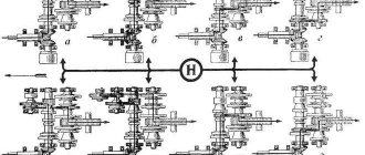
Transmission
The tractor is equipped with a manual gearbox with reverse and doubler, thereby expanding the speed range. The T-25's clutch is dry, single-disk, and permanently closed. The shafts are arranged transversely. The input shaft with a bevel gear is mounted on two ball bearings in the front part of the gearbox housing. In the middle of the shaft there is a reverse gear, to the right of which there is a gear of 2 and 4 gears, to the left - 1/3 and 5/6. The rear PTO drive and the set of low gears are located in the lower part of the body.
The clutch diagram of the T-25 tractor is shown in the photo.
All parts of the gearbox are protected by a cast housing.
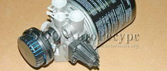
Hydraulic system of the T-25 tractor
Hydraulics on the tractor allows you to control the operation of the hydraulic systems of the attachments used for operation. The hydraulic system of the T-25 tractor includes a pump, a tank for filling oil, one or more high-strength power cylinders, an oil pipeline and a hydraulic distributor.
The pressure in the provided system is generated by the operation of a gear oil pump. Under pressure, oil enters the internal cavity of the distributor. Depending on the location of the spool, the oil passes to the lower or upper part of the hydraulic cylinder, moving the piston in the direction required for operation.
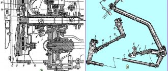
Set of attachments
The rear linkage mechanism is located between the rear wheels. It is a structure consisting of a connecting chain, one central and two longitudinal rods, which are attached at one end to brackets connected to the vehicle’s gearbox. Longitudinal rods with lifting arms are combined with braces. Through the lifting shaft they receive force from the cylinder. The hitch is attached to the free ends of the longitudinal and central rods.
The hydraulic system ensures the operation of trailed and mounted equipment, including raising and lowering the hitch mechanism. It includes an oil tank, gear pump, power cylinder, hydraulic distributor and oil lines. The oil pump creates pressure in the system. As a result, oil flows first into the distribution chamber and then into the hydraulic distributor, causing the piston to move.
Tractor Vladimirets T-25 – technical characteristics
The T-25 tractor has earned great popularity among the people due to its good operational parameters.
Technical characteristics of the tractor as standard include:
- diesel engine power – 20 liters. With.;
- number of travel speeds – 8 forward/6 rear;
- front drive axle – 120–140 cm;
- rated speed of rotation of the power take-off shaft – 540 rpm;
- maximum weight of transported cargo – 600 kg;
- Fuel consumption at average loads is 223 g/kW. h;
- weight –2.020 t.
The T-25 tractor has very modest dimensions for a universal unit. The length of the agricultural machine is 3.18, width – 1.47, and height – 2.47 m.
Reviews from owners of the T-25 Vladimirets tractor indicate the high maneuverability, endurance and cross-country ability of the unit. He is capable of performing the most complex agricultural operations, from planting to harvesting and transporting crops.
Maintenance
To extend the life of the tractor, it is necessary to carry out timely technical support. The car is cleaned of dirt after each trip to the field. Caring for the body helps to avoid corrosion of the body metal.
The engine oil is changed every 240 hours of operation. This model is suitable for M-10G2k or M-10B2 oils. The oil in the hydraulic system is changed after 500 operating hours. Any STOU type compositions are suitable for T-25. Transmission fluids must be replaced once a year before seasonal work. Typically, Tap-15V or TAD-17i oils are chosen.
Maintenance is also carried out when malfunctions in the operation of the tractor are identified. If the engine does not start, check:
- setting the crankshaft starting frequency;
- presence of dirt in the fuel system and air filters;
- serviceability of the fuel pump;
- adjusting the injection advance angle;
- condition of injectors;
- fuel quality.
If smoke comes from the engine, this indicates:
- insufficient air supply;
- low fuel quality;
- increased load on the engine;
- low fuel injection angle;
- malfunction of the nozzle spray needle;
- sticking of nozzle holes.
T-25 tractors have been helping farmers for more than half a century. During this time, they have undergone a number of changes, but still remain the standard of reliable and productive equipment for small and medium-sized farms.
Areas of application of the tractor on the farm
The operating instructions included with the T-25 tractor indicate that the unit can be used to solve various agricultural problems.
The following attachments can be used with the tractor:
- A plow is used to cultivate hard clay soils, including virgin soil. At the same time, plowing the land with the T-25 tractor can be carried out using either a small-sized single-hull plow or a larger double-hull plow;
- for planting and caring for the crop - for this, a hiller, lugs, as well as equipment for distributing fertilizers and pest control agents are used;
- a cart can be used to transport crops, the total weight of which together with the load should not exceed 600 kg;
- A mower is used to mow weeds and bushes of tuber crops;
- a milling cutter is used to remove weeds from rows;
- For the purpose of clearing snow from the local area and leveling the soil in the garden, a blade can be used.
Together with the T-25 tractor, you can actively use various homemade products: harrows, plows, cutters, seeders, mowers, wood splitters, equipped with hydraulic systems. Vladimirets will tell you about the capabilities of the tractor when working on the farm in more detail in the video. If necessary, the T-25 tractor can be modernized by replacing the standard engine and modifying the hydraulic system - this will significantly expand the scope of application of the unit in agriculture and everyday life.
Homemade potato digger for tractor T-25
A potato planter for the T-25 tractor paired with a potato digger for the unit allows you to plant and harvest tuber crops, spending a minimum of effort and time on the work.
The operating principle of self-made equipment for digging up potatoes is quite simple. However, to make the device as effective as possible, you will need to put a little effort into assembling it. The procedure for making a potato digger is as follows:
- First you will need to make a reliable support frame. To do this, you need to use 4 channels connected to each other by 4 reinforcing corners;
- Next, you need to bolt the elevator to the frame. Thanks to the bolted connection, the farmer will be able to change the angle of inclination of the elevator used;
- Then you will need to equip the reduction unit. To make it, you will need to use a “glass”, a bushing and two metal cylinders - all these spare parts are necessary for fixing the drive and driven shafts;
- To attach the potato digger to the tractor, you need to make an input axle. To do this, you will need to make holes in the side walls of the elevator casing. Next, you need to put a gear with a welded bearing, a spacer wheel and 2 bushings on the stud.
As a result of the work, it will be possible to produce a single-row potato digger, which in its reliability and characteristics will be practically not inferior to factory analogues.