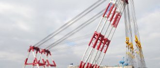
A beam crane is a popular design that allows you to lift and drag heavy loads indoors, as well as under canopies or awnings. It is mounted directly under the ceilings and moves along installed rail tracks. It features a simple design and low requirements for daily maintenance. Subject to compliance with operating and safety requirements, it will serve for years without any failures.
The electric beam crane has an electric drive, which:
- increases the performance of the device many times;
- reduces operating time;
- makes the work process much more comfortable.
Indeed, with this solution, the movement of the crane occurs under the influence of electric current, and not through human effort. This is more economically profitable, plus it requires little labor on the part of the operator.
Winch control
When the SB1 button is pressed, power flows through the current relay, the normally closed limit switch contact and the KM2 starter contact, and turns on the KM1 starter electromagnet. The KM1 starter supplies power to the M1 motor, as a result of which the lifting of the load is turned on. A current relay (RT) is necessary to prevent prolonged operation of the engine in overload mode. The limit switch is necessary to stop rotation when the hook reaches the upper limit position in order to avoid damage to the winch or its drive. The power supply of the KM1 starter is passed through the normally closed contact of the KM2 starter to avoid their simultaneous activation. If this is not done, then if 2 starters are turned on at the same time, a short circuit will occur in the power part of the circuit at the contact areas of the contact groups, which will disable them. Such circuits for connecting starters to each other are called interlocking circuits.
In order to lower the load, press the SB2 button. When it is pressed, current flows through the normally closed contact of the limit switch of the lowest position. And the normally closed contact of the KM1 starter, passing through the coil of the KM2 starter, starts reverse rotation. The limit switch is necessary to avoid rewinding of the cable.
Hoist control
To move the electric crane hoist, relatively speaking, to the left, press the SB3 button. The current will flow through the normally closed contact of the limit switch located at the left extreme point of the hoist. When the hoist reaches the limit left position (collision with the rubber buffer), it will cut off the power supply to the KM3 starter in order to avoid overloading the electric motor and excessive wear of the wheels due to their spinning in place. Power supply to the KM3 starter is also provided through the normally closed contact of the KM4 starter for the same purpose of protecting the starters from simultaneous switching on.
To move the hoist, relatively speaking, to the right, press the SB4 button. The supply voltage will go to the normally closed contact of the limit switch, and after passing through it, it will go to the normally closed contact of the KM3 starter, and only after that it will power the coil of the KM4 electromagnet, which will turn on the reverse rotation of the engine. If the right extreme point collides with the right buffer, the limit switch will cut off the power supply to the starter, as a result of which the rotation of the wheels will stop.
Cost of work and completion time
The cheapest systems for crane beams with single-speed motors.
For cranes, the cost depends on: a) the presence of magnetic controller panels in the electric drive of the crane mechanisms; 6) if the mechanism has a power (cam controller), then for higher power motors in the manufactured system larger electromagnetic starters will be used, and the cost of the system will increase accordingly; c) quantity mechanisms on the crane; d) type of remote control selected by the customer.
The time for production and delivery of the 1st set of the system is on average 20 working days.
The installation time for 1 set of the system on a tap is approximately 16-24 hours.
Electric crane-beam bridge control
To turn on the forward movement of the bridge, press the SB5 button. The starter is powered in the same way as in previous functions to provide the same protections. The reverse movement of the bridge works in the same way.
After finishing working with the mechanism, turn the key to the “OFF” position. and remove it from the lock. If you try to turn on any of the functions of the electric crane, the mechanism will remain motionless.
In conclusion, we can say that a beam crane is one of the simplest devices, but it greatly facilitates the work of an ordinary worker.
Popular models of management positions
Among the Russian developments, we can highlight the explosion-proof remote control PKIV-UPM. The device is designed to control crane beams installed in rooms with a potentially explosive atmosphere. The post is produced in a housing made of aluminum-silicon alloy and is resistant to salt fog and aggressive environments.
Among foreign analogues, we can highlight push-button modifications of the XAC class, produced on the market by Schneider Electric. This is a French enterprise that occupies a leading position in the world market for the production of energy subcomplexes and equipment.
The management positions of the Taiwanese company Telecrane have performed well. These are radio-controlled models in push-button and joystick versions. The operating range of the models reaches 100 meters; some devices support a 5-speed operating mode in each direction of hoist movement.
Electric drive of electric hoists and crane beams
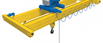
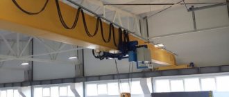
Suspended electric trolleys (electrified hoists, hoists and beam cranes) are used for lifting and moving loads and machine parts during installation and repair work inside industrial premises.
Electric hoists, hoists and beam cranes are smaller than overhead cranes, which reduces the size of industrial buildings, and their maintenance does not require qualified personnel. Suspended electric trolleys are designed for lifting and moving loads at production facilities along a strictly defined path.
The suspended electric trolley (Fig. 1) consists of 3 main parts: a lifting mechanism (electric hoist), designed to lift (lower) and hold the load, a movement mechanism (undercarriage), designed to move the lifted load in a strictly defined direction, a monorail that determines the horizontal movement in two directions.
Rice. 1. Kinematic diagram of a suspended electric trolley
The electric hoist is mounted on a running trolley and includes the following equipment: an electric motor (5) of the lifting mechanism, a cylindrical gearbox (10) to reduce the rotation speed of the electric motor to a value that provides a given linear speed of lifting (lowering) the hook, an electromagnetic brake (9) to brake the shaft engine when it is disconnected from the network or the voltage in the network disappears, a shoe brake is used, powered by the force of springs when the shaft is covered by blocks, a hook end switch (7) to limit the lifting of the hook, when pressed, the engine is disconnected from the network and braked, a rope drum (6), for winding (unwinding) and storing the rope, hook (8), for securing the lifted load.
Safety Standards
The following requirements are put forward for control panels for crane beams:
- Integrity - the post must be grounded; there should be no cracks or other damage in the housing.
- Security - the key mark that closes/opens the crane control circuit is located only by the operator or the responsible person appointed by order of the enterprise.
- Maintenance – elements of crane equipment are regularly inspected and maintained; if loading and unloading operations are carried out outdoors, a waterproof remote control is used for control.
- Operability – the directions of movement on the control buttons are maintained throughout the entire operational period, the keys should not stick: they independently return to the initial position after the pressing stops.
- Installation - the cable length of the wired remote control must ensure that the operator is located outside the loading area; stationary control stations are installed at a distance of 1-1.5 meters from the floor.
When installing overhead cranes with floor control, passages must be left for operating personnel.
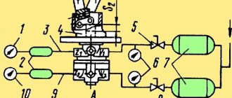
Wiring diagram of the crane beam
The electrical circuit diagram of a beam crane for any model includes a gearbox, a drum and an electric drive.
The gearbox is responsible for reducing or increasing turns during operation.
Like most overhead cranes, overhead cranes use a drum that winds a load cable to lift the load to the desired height.
The engine is the center of any electric hoist and hoist. The motor power is calculated taking into account the weight of the structure and the tasks facing the lifting device.
Rice. 1. Electrical diagram of the crane beam with description
Figure 1 shows a standard electrical circuit for a overhead crane. The electric motor is controlled using reversible magnetic starters and program buttons connected to the drive with a flexible cable.
Power is supplied to the windings and contacts of the contactors for raising (KM1) and lowering (KM2), as well as for moving forward (KMZ) and backward (KM4) through a flexible cable on which a switch is installed that automatically stops the current supply when the load on the electrical network is high.
The SQ limiter slows down the movement of the lifting device when the height or weight of the lifted load is exceeded.
Distribution el. The crane beam diagram shows the energy distribution of power to the lifting device components. Using special distributors, current is supplied at the required voltage to each working mechanism. Special adjustment devices connected to an electric motor using a flexible cable or trolley are responsible for this.
On the electronic diagram of the crane beam, switches and switches are displayed as a starter system for control. They are life-size software boxes with buttons that control the movement of the cargo cable: up, down, forward, backward. The casing is made of an ebonite or plastic shell that does not allow electric current to pass through.
The electrical circuit diagram of an overhead crane and any type of lifting equipment is developed based on the purpose of the device. The principles of connecting the engine and the lifting device are laid down at the design stage, after which production begins.
The standard voltage for material handling equipment is 380 V. This not only ensures the operation of the crane, but also the fuses and safety systems. Often the control circuit is made with the expectation of issuing commands from the floor using a radio remote control or flexible cable.
As a result, the operator will be able to remain at a decent distance from the lifting machine.
Execution options
There are two types of wired and wireless remote controls: push-button and joystick. Push-button remote controls are considered more practical to use, therefore they are installed on most models of crane equipment.
These controls have the following advantages:
- Ease of manufacture, which reduces the cost of equipment as a whole.
- Ergonomic design.
- Reliability: there are no technically complex parts or electronics.
- Ease of use: an intuitive control scheme does not require special skills and knowledge.
Here it is necessary to clarify that radio frequency stations are more convenient to use, but are much more expensive than simple relay-contactor panels. In addition, radio-controlled stations require complex setup and expensive repairs if they fail.
Joystick remote controls provide more precise positioning of the load in space: it provides stepwise adjustment of the direction of movement. The remote control is worn around the neck, which frees the operator's hands. In addition to joysticks, the layout of the post provides additional keys, light and sound indicators that display the technical condition of the device.
Video: remote control of a crane.