- home
- Media center
- Articles
- KAMAZ trailer brake control valve
Menu
- News
- Articles
- Video materials
- Photo materials
- Publication in the media
- 3D tour
03.03.2020
A modern KAMAZ trailer brake control valve is used to control the brake elements at the moment the same truck system is activated. Its task also includes automatically turning on the brake elements if the pressure in the main element drops to the lowest level. This unit drive is a combined one; they can be single- or double-drive. It is worth taking a closer look at the design details, structure and method of connecting the tap.
What does the faucet consist of?
The valve regulates the operation of the semi-trailer's braking elements and moves recycled air from the main source to the remaining consuming elements, which can operate synchronously or separately. Commands must be sent to the double outlet openings to increase the pressure in the main part; one similar opening is subject to the opposite type of action. It can influence the pressure level to decrease while releasing the air mixture using a manual lever.
The faucet is complemented by a main valve consisting of three sections, as well as large and small pistons with springs. The middle one is supplemented with an inlet valve that presses the spring towards the landing socket. The structure of the part is not limited to the main element. Additionally, the valve consists of a diaphragm, a discharge outlet, a rod and an adjusting screw. In the uninhibited mode, compressed air constantly flows to the outlet, affecting the piston element and diaphragm, it holds them together at the bottom.
This effect is also achieved due to the increased diaphragmatic area. In the upper part, a collection of pistons is located on the top, while the exhaust valve element is separated from the seating area. At this time, the inlet part is closed under the influence of the spring. One of the output parts connects the brake control line with the atmospheric outlet due to the rod and unloading elements.
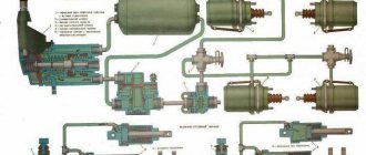
KAMAZ-4310 trailer brake drive
Military Encyclopedia - historical and archival military-patriotic portal
home☆Soviet military encyclopedia☆military equipment☆military science☆military review☆history of weapons☆forum
military equipment ☆ articles on the VAT device ☆
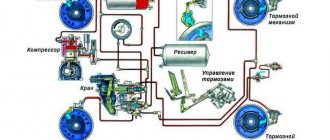
The trailer brake drive is combined, two-wire and single-wire. This means that all trailers that have one or another type of pneumatic brake drive can be connected to the KamAZ-4310 vehicle.
With a two-line drive, compressed air is constantly supplied through one pipeline from the vehicle’s pneumatic system to the trailer’s air cylinders, and the trailer’s braking system is controlled through another pipeline. With a single line drive, the same line is used to fill the trailer's air tanks between brakes and control the trailer's brakes.
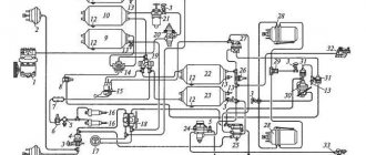
The two-wire drive includes a valve 30 (see Fig. 145) for controlling the brakes of a trailer with a two-wire drive, a single safety valve 31, two disconnect valves 34, two connecting heads 36 of the Palm type, and a pipeline.
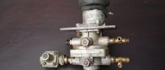
The trailer brake control valve (Fig. 159) is designed to control the trailer brake system with a two-wire drive, as well as to activate the trailer brake system with a single-wire drive; installed at the rear of the frame.
The main parts of the valve are the upper 5, middle 13 and lower 15 housings, large and small upper pistons with springs 10 and 8, middle piston 12 with inlet valve 4 and rod 14, outlet valve 11. A pipeline from the lower section of the brake valve is connected to terminal I working system; to terminal II - from the manual brake valve, to terminal III - from the upper section of the brake valve of the working system, to terminal IV - from the trailer control line, to terminal V the pipeline from the air cylinders of the third circuit is connected.
In the braked state, compressed air is constantly supplied to terminals II and V, which, acting from below on piston 12 and from above on diaphragm 1, holds piston 12 together with rod 11 in the lower position, since the area of the diaphragm is larger than the area of the piston. In the upper part of the piston body 6 and 9 are in the upper position under the action of spring 10. In this case, the inlet valve 4 is closed, the outlet valve 11 is open. Thus, terminal V is connected to the atmospheric terminal U; air pressure is not supplied to the control line.
Rice. 159. Control valve for the trailer brake system with a two-wire drive: a - device; b - inhibited position; in - position when braking with the service brake system; g - position when braking with the parking or emergency brake system; I — output to the lower section of the brake valve; II - output to the manual brake valve; III - output to the upper section of the brake valve; IV - output to the line to the trailer, V - output to the air cylinder; VI - atmospheric output; 1 - diaphragm; 2, 8, 10 - springs; 3 — unloading hole; 4 — inlet valve; 5 — upper body; 6 — upper large piston; 7 - adjusting screw; 9 — upper small piston; 11 — exhaust valve; 12 - middle piston; 13 - middle body; 14 - rod; 15 - lower body.
When braking with the service brake system, compressed air is supplied from the valve sections to terminals I and III. Under the action of air pressure supplied to terminal I, diaphragm 1 bends and rod 1, together with the middle pistons 12 and valve 4, rises. Compressed air supplied to terminal IV moves the upper pistons 6 and 3 down. As a result of these movements, the exhaust valve 11 closes and the inlet valve 4 opens. Compressed air from terminal V passes to terminal IV and then into the control line.
When the brakes are released, the compressed air from terminals I and III escapes into the atmosphere through the brake valve. Pistons 6 and 9, under the action of springs and compressed air, occupy the upper position, rod 4 with piston 12 occupy the lower position. The outlet valve 11 opens and communicates the control line with the atmosphere.
When compressed air is supplied to terminals I and III, rod 14 with piston 12 or pistons 5 and 9 move downwards, respectively. The valve operates in the same way as when air is supplied simultaneously to terminals I and III.
When braking with the spare or parking brake systems, compressed air from port III is released into the atmosphere through the hand brake valve. The pressure in the cavity above the diaphragm drops, thereby reducing the force acting on the rod 14 and the piston 12 from above. Under the influence of air pressure supplied to terminal V, the piston and rod move upward, while the outlet valve 11 closes and the inlet valve 4 opens. Compressed air from terminal V is supplied through terminal IV to the control line. The trailer brake control valve has the following action. As the pressure in the control line increases, the pressure in the cavity between pistons 9 and 12 also increases, while piston 9 moves up, piston 12 moves down. When the pressure in the control line is reached, proportional to the pressure supplied to terminals I and IV (or removed from terminal II), the inlet valve 4 closes, and the outlet valve 11 remains closed. The pressure in the control line stabilizes.
When air is supplied to terminal III or simultaneously to terminals 1 and IV, the pressure in terminal IV exceeds the pressure in terminal III by 20 ... 100 kPa, which ensures a leading action of the trailer brakes. The control overshoot is adjusted using screw 7.
Single-pair safety valve 31 (see Fig. 145) serves to protect the pneumatic drive of the tractor from loss of compressed air in the event of damage to the trailer drive or connecting lines. In addition, the valve prevents compressed air from escaping into the trailer line in the event of a leak in the drive of the towing vehicle, thereby preventing automatic braking of the trailer.
Valve 31 is the same as valve 16, installed in the third circuit (see Fig. 153).
The diaphragm type disconnect valve 34 (see Fig. 145) is designed to disconnect the vehicle brake system from the trailer brake system. When installing the valve handle along the body, pusher 5 (Fig. 160) together with rod 3 is in the lower position and valve 2 is open. Compressed air passes from the towing vehicle to the trailer.
Rice. 160. Isolation valve: a - the valve is closed; b - the tap is open; I - output to the trailer brake control valve or to the car’s air tank through a single safety valve; II - output to the trailer brake control line or to the trailer air points; III - release into the atmosphere; 1 - spring; 2 - valve; 3 — rod with diaphragm; 4 — return spring of the rod; 5 - pusher with handle.
If the valve handle is installed across the body, the rod with the diaphragm rises up under the action of compressed air and springs 4. Valve 2 closes, disconnecting terminals I and II. Compressed air from the connecting line escapes to the atmosphere through outlet III.
Rice. 161. Connecting head of the “Palm” type: a - tractor; 6 — trailer and tractor; 1 - body; 2 - seal; 3 - cover; 4 - latch.
Connecting heads of the “Palm” type (Fig. 161) are designed to connect the lines of a two-wire pneumatic drive of the brakes of a trailer and a tractor. The heads are valveless, have a rubber seal 2 and clamps that hold them in a locked state. Both heads are mounted on the rear cross member of the frame. One head is painted red and is connected by pipelines through a single safety valve to the third circuit air cylinders (supply line). The second head is painted blue and is connected to the trailer brake control valve with a two-wire drive (control line).
The brake system of a trailer operating with a vehicle consists of brake mechanisms according to the number of wheels and a pneumatic drive, which includes air cylinders, brake chambers, a release valve, an air distributor, pipelines and hoses.
Rice. 162. Trailer air distributor: 1 - bottom cover; 2 - body; 3, 7 - rubber cuffs; 4 - rubber ring; 5 - rod; 6 — top cover; 8, 12 — pistons; 9 - check valve; 10 - retaining ring; 11 - unloading valve:
The air distributor (Fig. 162) serves to control the trailer brakes, is installed on the trailer and is the main device of its pneumatic braking system. It consists of a body 2, lower 1 and upper 6 covers, a rod 5 with an upper piston 8, a lower piston 12, a check valve 9 and a relief valve 11. Compressed air is supplied to cavity A of the air distributor from the air cylinder of the third circuit of the towing vehicle (supply line), cavity B is connected to the air cylinders of the trailer, cavity B is connected to the brake chambers of the trailer, cavity D is connected to the atmosphere, air is supplied to cavity D from the control valve trailer brakes with a two-wire drive (control line).
Operation of a two-wire drive. In the inhibited state, compressed air from cylinders 21 (see Fig. 145) of the third circuit through a single protective valve 31, disconnect valve 34, and connecting head passes through the hose into cavity A (see Fig. 162) of the air distributor, opens valve 9 and through the cavity B fills the trailer's air tanks. At the same time, compressed air from the same cylinders 21 (see Fig. 145) is supplied through the control valve 30, which connects the trailer control line, and therefore the cavity G (see Fig. 162) of the air distributor with the atmosphere.
By air pressure in cavity A, piston 8, together with rod 5 and piston 12, is raised upward, while valve 11 is closed. The trailer brake chambers are connected to the atmosphere through cavities B and D. When the pressure difference in cavities A and B becomes equal to 1O...2OkPa, valve 9 closes.
When braking with the working, parking or spare brake systems, compressed air from the same cylinders 21 (see Fig. 145) through control valve 30 is supplied to the control line and into cavity G (see Fig. 162) of the air distributor. By air pressure on the piston 8 from above, the rod with the lower piston 12 goes down, while first the valve 11 is pressed into the seat of the bottom cover, separating the cavity B from the atmosphere, and then the gap opens between the valve 11 and the piston 12 and compressed air from the trailer cylinders through the cavity B passes into its brake chambers.
As the air pressure in cavity B increases, the lower piston 12 rises and the gap between this piston and valve 11 closes; equilibrium is established between the air pressure in cavities G and C. This shows the tracking effect of the air distributor.
When the brakes are released, the compressed air from cavity G escapes into the atmosphere through the control line of the trailer brake control valve. The air distributor parts are installed in the position they occupied before braking.
The single-line trailer brake drive includes a type “A” connecting head 31 (see Fig. 140), a disconnect valve 34, a control valve 35, pipelines and hoses.
Fig. 163 Connecting heads of type “A” and “B”: a – connecting head of type “A”; b - connection of heads of type “A” and “B”: 1 body; 2 - spring; 3 - check valve; 4 - valve seat; 5 - pin.
The connecting head of type “A” (Fig. 163) is used to connect a single-drive actuator for the trailer brakes, as well as to automatically close the tractor line in the event of disconnection from the trailer (for example, during separation). The “A” type head is mated to the “B” type head of the trailer. The head has a valve 3, which is opened using a pin 5 when connected to a type “B” head. In the disconnected state, valve 3 is closed under the action of spring 2.
Fig. 164. Trailer brake control valve with single-wire drive: a - device; b — inhibited position; c — position during braking; I - output to the trailer brake system; II - release into the atmosphere; III - output to the trailer brake control valve with a two-wire drive; IV - output to the air cylinder; I - tracking camera; 2 - stepped piston; 3 - working chamber; 4 — power spring; 5 - diaphragm;. 6-pusher; 7 - channel; 8 — exhaust valve; 9 — inlet valve; 10 - spring; 11 — adjusting screw; 12 - lower piston; 13 - connecting chamber.
The control valve (Fig. 164) for trailer brakes with a single-line drive is designed to actuate the trailer brake system when the tractor brake systems are operating, as well as to limit the pressure in the pneumatic drive of the trailer in order to prevent the latter from self-releasing when pressure fluctuations in the drive of the tractor vehicle. The valve consists of a body with upper and lower covers, a diaphragm 5 with a pusher 6, a staged piston 2, a lower piston 12, inlet valves 9 and exhaust valves 8. Pin I is connected to the trailer line, pin II is connected to the atmosphere, pin III is connected to trailer brake control valve 1, with a two-wire drive, pin IV is connected to the air cylinders of the third circuit.
With a single-line drive, the line from the control valve of the tractor vehicle is connected to cavity A of the air distributor (see Fig. 162); cavity D is not used in operation.
Single-wire drive operation. In the braked state, the cavity under the diaphragm 5 of the control valve (see Fig. 164) is connected to the atmosphere through terminal III and the two-wire drive valve. Under the action of springs 4, the diaphragm 5 together with the pusher is in the lower position, while the outlet valve 8 is closed and the inlet valve 9 is open. Compressed air from the third circuit cylinders passes through terminal IV and valve 9 to terminal I and then into the line to the trailer air distributor. When the pressure in this line reaches 500...520 kPa, the lower piston 10, overcoming the forces of the spring, is released, and the inlet valve 9 closes. The pressure in the trailer line is slightly lower than in the tractor drive. When braking, compressed air from the two-wire drive valve is supplied to terminal III and fills the piston under the diaphragm. The latter, together with the pusher, rises up, the inlet valve 9 closes (if it was not closed), the outlet valve 8 opens. Compressed air from the trailer connecting line from port I through valve 8, the hollow rod and port II exits to the atmosphere. The drop in pressure in the connecting line, and therefore in cavity A of the air distributor (see Fig. 162), leads to the fact that the lower piston 12, under the influence of pressure in cavity B, falls down, cavities 3 and D are separated, valve 11 moves away from piston 12 and through The resulting gap allows compressed air from the trailer's cylinders to pass into its brake chambers.
Air from valve outlet 1 (see Fig. 164) escapes into the atmosphere until the pressure in the cavities under diaphragm 5 and under piston 2 is balanced with the pressure in the cavity under piston 2 (in follow-up chamber 1, connected by channel 7 to outlet IV). With a further decrease in pressure at port II, piston 2 lowers and moves pusher 6 down, which closes valve 8, resulting in the release of air from the trailer line
stops. Thus, the trailer is braked with an efficiency proportional to the amount of compressed air pressure supplied to terminal IV.
When braking, the pressure under the diaphragm 5 drops, the latter goes down under the action of the spring, the outlet valve 8 closes, the inlet valve 9 opens and compressed air from outlet IV enters outlet I and then into the connecting line of the trailer.
When the pressure in cavity A (see Fig. 152) of the air distributor increases, piston 8 with rod 5, lower piston 12 rises up, the annular chain between valve 11 and piston 12 closes, cavity B is connected to cavity D and compressed air from the brake chambers of the trailer exits into atmosphere.
Tags: KAMAZ 4310 ☆ brake systems ☆ vehicle design ☆
| Auxiliary braking system KamAZ-4310 < Prev. | Track. > Service brake system URAL-4320 |
We recommend recycling old household appliances
Garbage removal in Moscow and the Moscow region
- Contacts:
- +
- around the clock
- Moscow
© Military Encyclopedia. Map of site.
How does the valve work when braking?
The valve from the valve that controls the brakes transfers recycled air during braking from the sections of the device to its outlets. From the next outlet in the air tank, the processed mixture passes to the control outlet and then passes into part of the main line. In it, the air flow influences the piston until it is balanced by the upper pressure. The upper piston element operates by compressing air and a spring.
The middle piston element is also balanced due to the work of similar factors. During the release of the air mass in compressed form, it exits through the atmospheric channel from the overcrowded compartments. Due to the compression of the spring and the air mixture, the piston parts move upward, after which the rod with the piston element moves down. The valve is detached from the seat and both the internal and external outlets are connected. The compressed air flow stimulates the movement of the rod with the piston element upward.
At the same time, the large and small piston parts go to the lower part, after which the brakes begin to function in the same way. After activating the backup or parking system inside the truck, air begins to escape through the atmospheric hole in the manual check valve and is released to the outside. The pressure level above the diaphragm element is reduced, thereby reducing the force on the working parts. The seat begins to rest against the valve element and separates the outlet from the atmosphere.
Important information!
In the tap, the line pressure begins to increase to the level until the mass acting on the piston from the bottom begins to equalize the influence on its diaphragm element. In this case, the tracking work of the crane is improved.
Design and principle of operation of the brake release valve
The CD has a simple structure and operation. Let's consider the functioning of this unit using the example of a trailer crane from the Kama Automobile Plant.
The unit can be installed directly on the air distributor housing or located nearby in a more convenient location. Its pipe I is connected to the trailer/semi-trailer receiver through the air distributor channel or a separate pipeline. Pipe II is connected to pipe I of the air distributor, and pipe III is connected to the car's main line.
During the main operation of the trailer, rod 1 is in the upper position (it is fixed in this position by means of spring-loaded balls that rest against recesses in the body of the device), air from pipe III flows to pipe II, and port I remains closed, so the valve has no effect for the operation of the air distributor.
If it is necessary to move the uncoupled trailer, you need to move rod 1 down using the handle - this will lead to the separation of pipes II and III and the connection of pipes II and I. As a result, air from the receiver is directed to the inlet I of the air distributor, the pressure on it increases and processes similar to to the release processes with a single-wire pneumatic drive circuit - the trailer is released. To brake, you must return the rod to the top position.
Device elements
Brake system control valve in a KAMAZ trailer
also consists of additional parts. This list includes a single safety valve designed to maintain pressure in the air reservoir if it drops to a critical level. It also prevents the leakage of compressed air in the event of an emergency decrease in pressure in the vehicle drive, thereby preventing involuntary braking of the trailer. Another important element is the disconnect valve, designed to shut off the pneumatic line that connects the tractor with the trailer.
When installing the handle of the element along the axis of the valve itself, the pusher element and the rod will be at the bottom, and the valve will open. The air will begin to pass through it in a compressed state, then it will be removed from the car to the semi-trailer. If the handle is in the middle part of the main element, the rod and diaphragm begin to move upward under the influence of air pressure with a spring. The valve is capable of blocking the terminals when it is in the seat. The air mixture passes into the atmosphere from the connection system, due to which the connection heads are disconnected.
Design and principle of operation of brake air distributors
Today, a large number of models of air distribution valves for trailers and semi-trailers are produced, but they all have a fundamentally identical design. The unit combines several pistons and valves that switch the line from the tractor, the receiver and the wheel brake chambers, depending on the condition of the brake system of the tractor. Let's consider the design and operating principle of a universal (used in both single- and 2-wire brake systems) air distributor for KAMAZ trailers with a separate brake release valve.
Let us immediately note that the air distributor controls the trailer braking system only when using the main braking system of the tractor. If your tow vehicle is equipped with a backup or parking brake system, a solenoid valve controls the air supply to the trailer brake system components. We will not consider the operation of this node here.
System operation
When the brake system is activated, compressed air passes from the double-circuit valve to the valve element of the single-line valve that controls the brake part from the MAZ trailer. This mixture is capable of filling a single plane under the diaphragm element. When the spring force is overcome, the diaphragm moves to the top along with the pusher, then the intake valve closes and the exhaust element opens. The air does not enter the atmosphere through a special outlet, a pusher and an outlet in the lid.
A stepped piston is responsible for the tracking action. As the pressure at the outlet stage and in the cavity decreases, the force on the lower piston part simultaneously decreases. In the upper part it is influenced by the pressure from a particular cavity, which is similar to the force in the second part of the valve. The hub will only accept the force from the first cavity. As a result, due to the difference in pressure levels, the piston begins to move down and drags with it the pusher element, which closes the exhaust window with the seat.
Important information!
When the pressure level increases further, the air mixture begins to flow out of the main brakes from the semi-trailer. In this case, the pushing part is located at the bottom edge, the inlet window is blocked, and the exhaust element opens.
Operation of the air distributor with a two-wire air distributor circuit
Two lines from the tractor are connected to the air distributor - the supply line to pipe I and the control line to pipe V. The remaining pipes have a connection similar to a single-wire circuit. Also, with a 2-wire circuit of the pneumatic drive, equalizing valve 10 comes into operation. With this connection circuit, a higher pressure is supplied to pipe I than with a single-wire circuit, which makes it difficult for the piston 2 to move and disrupts the operation of the entire brake system. This problem is eliminated by an equalizing valve - at high pressure it opens and connects the cavities above and below the piston, equalizing the pressure in them.
Connection of a trailer/semi-trailer with a tractor. Road train movement. In this case, air from the supply hose fills the receivers through pipes I and IV; the remaining components of the air distributor do not work.
Braking a road train. When the tractor is braked, the pressure at port V increases, compressed air enters the chamber above the piston 11, forcing it to move down. In this case, the processes described above occur - valve 5 closes, valve 7 opens, pipes IV and III are connected, and air from the receivers enters the brake chambers, performing braking.
Release of the brakes of the road train. When the tractor is released, all processes occur in the reverse order: the pressure on pipe V drops, the piston rises, pipe III connects to pipe II, the air is released from the brake chambers and the trailer is released.
Emergency braking in case of a line break, trailer disconnection. In these cases, the role of the tracking mechanism is performed by the equalizing valve. When the pressure on pipe II drops to atmospheric pressure, the valve closes, separating the chambers above and below piston 2. As a result, the pressure above the piston (due to the air coming from the receivers through pipe IV) increases, and processes similar to braking with a single-wire connection scheme occur. Thus, in the event of a rupture/disconnection of a hose or when the road train disassembles, the trailer/semi-trailer is automatically braked.
Single safety valve
This element serves to maintain pressure in the air tank of the tractor in the event of a critical decrease in this indicator in the supply line of the semi-trailer. In addition, it prevents the leakage of compressed air from the system during an emergency decrease in pressure in the vehicle drive, which helps prevent unauthorized braking of the towbar.
The single valve is adjusted to bypass air when the outlet pressure reaches 550 Pa. The compressed mixture enters through the outlet into the working niche under the diaphragm, then into the cavity in front of the valve. From there it goes to the exit of the main highway. The required pressure value is adjusted using the adjusting screw.
Short description
The trailer brake control valve consists of the following elements:
- Pair control valve and similar single element.
- Two isolation valves.
- A pair of connection heads.
The valve is responsible for controlling the brakes of the semi-trailer, directing compressed air from the input source to subsequent consumers, working both synchronously and separately. A command is sent to two outputs to increase the pressure in the line, and one analogue receives the opposite action, affecting a decrease in pressure when releasing the air mixture using a hand lever.
Automatic braking
When the supply line ruptures, the Volvo trailer brake control valve receives a sharp drop in pressure, as a result of which the load on the piston is removed. Under the force of the spring, the piston moves upward, and the valve closes the outlet. The piston part with further movement releases the inlet window.
Through the outlets, the pressure from the receivers is fully supplied to the brake cylinders. If the line breaks, the DAF trailer brake control valve operates according to a similar scheme as described above. This is due to the fact that the pressure in the supply structure of the crane also decreases due to leakage of the unit after the tractor starts braking.
Working in a disinhibited state
In the inactive position, air in compressed form flows from the parking brake system cylinder to the outlet, which is connected to the atmosphere via a control valve. Under the influence of the power spring, the diaphragm and pusher are located in the lower position. The exhaust valve remains closed, while the intake valve operates open, allowing air to flow to an outlet that connects to the single-line brake control line.
Synchronously compressed air is supplied to special cavities, the pressure in which remains equal. Taking into account the fact that the area of the stepped piston is larger, it moves upward until it stops. When the pressure in the trailer brake line chamber reaches about 500-520 Pa, the lower piston goes down and blocks the inlet valve. When the brakes are released, the system automatically maintains a pressure level of 500 Pa, which is slightly lower than the same parameter in the pneumatic drive of a truck.
Peculiarities
In the trailer brake control valve, the main pressure is built up until the force acting on the piston from below is equal to the force applied to the diaphragm. This ensures follow-up operation of the valve.
When the compressed air mixture simultaneously approaches the working terminals, and the pressure in the compartment connected to the main line, and the pressure value exceeds the same value in the control terminal (20-100 kPa), the brakes act proactively. The required pressure value is adjusted using the adjusting screw by tightening or unscrewing it.