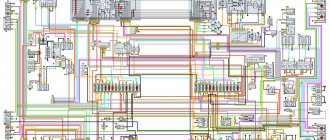
Car owners who have not previously encountered domestic off-road versions are always confused by two, at first glance, different names for the same model. In particular, if you need a wiring diagram for a UAZ 31512, then you should look for documentation for the “459B” model of the Ulyanovsk Automobile Plant, since this is the same vehicle.
The electrical circuit of the UAZ 31512 is identical to the UAZ 459B
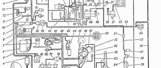
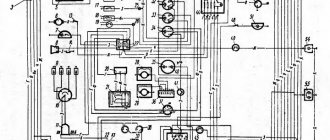
Wiring diagram for loaf with carburetor engine
To connect electrical appliances to the system of a car with a carburetor, an old-style circuit is used - a loaf designed for UAZ cars produced in 1954 - 1984.
Why might you need a wiring diagram for such a car? The need for instructions for wiring in a car may arise not only if some defect that interferes with the operation of the vehicle is corrected, but also when the wiring is re-installed.
It is worth remembering that there are two circuits for a car with a carburetor engine. The first is a simple one, in which there is no electronic carburetor control unit (this element appeared after 1984 and is not included in the old circuits).
The second is a little more complicated (the connection to the carburetor control unit is taken into account). Such a scheme should be used if it is necessary to connect to the operation of all electronic systems of the car, and not just the ignition and the minimum necessary to drive the vehicle.
To conduct wires according to a simplified scheme, it is enough to stretch a wire from the battery through the toggle switch to the ignition to create a spark, and the second through the relay and button to the starter to make it possible to start the engine.
If the car's generator does not have a voltage regulator built-in, then you need to purchase one and connect it to the system.
Vehicle interior
The changes also affected the interior of the car, making the modification attractive and capable of competing with cars from similar manufacturers. The upholstery, dashboard, as well as the electrical circuit of the interior have changed.
UAZ “Hunter”, instrument panel:
- A new, informative instrument panel has been installed;
- Electric window lifts installed;
- Electrical diagram of the UAZ Hunter 315195 injector includes a relay that protects fuel injection. An electric glass and rear door wiper is installed;
- A new type of fuses are used to protect twenty-six vehicle circuits.
Source
Wiring diagram for a loaf with an injection engine.
When repairing electrical wiring in such a car, it is difficult to find a ready-made connection diagram - the manufacturer did not include it in the operating instructions.
It is believed that the wiring diagram for electrical appliances in UAZ loaf cars with an injection engine almost completely corresponds to the diagram that is used in a car with a carburetor, but in reality they are different.
To solve car control problems related to wiring, 2 connection schemes are used - standard for a loaf with a carburetor engine and injection for GAZ - 69 “Kozel”.
Combining the information from these two diagrams allows you to repair or reinstall the wiring in the injection loaf.
Instead of a circuit diagram for an injection GAZ-69, a circuit diagram for an electronic engine control system can be used, so drivers are advised to carry it with them along with a wiring diagram for a loaf carburetor engine.
Features of electrical equipment
For designers, a more difficult process in those years was to find high-quality components to equip the ignition and lighting systems.
This can be clearly seen from the filling of the cabin:
- vehicle system controls;
- control devices.
External lighting
Everything that could be obtained was used to ensure uninterrupted supplies to the factory conveyor.
Many UAZ owners know about the vagaries of classic ignition, which sometimes presents unpleasant moments. And often craftsmen find ways to modernize a problematic unit or an entire system. And one such method of improving the launch system with your own hands will be discussed in this publication.
basic information
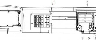
Fuses in a UAZ Bukhanka car are located in a special mounting block, which in turn is located in the air inlet box on the left side of the vehicle. The mounting block includes all the most important sections of electronic circuits, while supplying them with the necessary fuses and relays. The fuse box of the UAZ Bukhanka car consists of two lines with fuses and this entire structure is secured with a nut to the vehicle body. If you decide to remove the fuse lines, you will need to disconnect the battery.
The main elements of the electronic circuit include:
- Accumulator battery;
- Electronic fuel pump;
- Fuel mixture purification filter;
- Injectors;
- Engine control unit;
- Electronic ignition coil;
- Spark plugs;
- Idle speed sensor;
- Crankshaft sensor;
- Air damper sensor;
- Tachometer;
- Fan motor cooling the radiator;
- Electronic fan motor control relay;
- An indicator that monitors engine performance;
- Diagnostic connector.
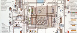
Wiring diagram UAZ Bukhanka
If any failure of electronic equipment occurs, the current in the node that is responsible for this device will increase, resulting in a short circuit. The wire through which the current passes to the fuse burns out and melts, as a result of which the circuit breaks and the device turns off, but its integrity is maintained. That is, thanks to fuses, the main parts are protected from overheating in the event of a short circuit.
How to properly remove and install the mounting block?
If the electrical circuit is made with high quality, it will greatly facilitate the process of installing and removing electronic equipment. So, the algorithm for removing the mounting block:
- Disconnect the wiring from the negative terminal of the battery;
- Open the hood and remove the cover from the fuse and relay box. To do this, you need to press out 4 plastic latches;
- Move the rubber cover;
- Disconnect the upper block of the wiring harness from the block;
- We unscrew the 2 nuts that secure the block;
- We take out the block from the compartment, which is located in front of the windshield;
- We disconnect the lower blocks of the wiring harnesses from the block;
- Install fuses and relays in reverse order.
Meet UAZ 452
The car was a cargo-passenger version of an off-road vehicle with a 4x4 wheel arrangement. The Ulyanovsk Automobile Plant mastered production of the model back in 1965.
You can evaluate its capabilities by watching the following video:
The UAZ 452 is capable of transporting cargo weighing up to 700 kg in the back. In addition, it can tow a trailer weighing 850 kg. The vehicle became very popular not only in Russian off-road conditions, but was also successfully used in large cities in various capacities (pictured in the article).
In particular:
- Like a traffic police car;
- As a fire engine;
- Ambulance car;
- Grocery store;
- Utility vehicle, etc.
Electronic components
The electrical wiring of the UAZ 452 was a simple single-wire circuit.
Structurally, it had the following solutions:
- The role of the second wire was played by the metal body and the components and assemblies attached to it;
- All electronic components and actuators had a “-” displayed on the housing. The cost of such a solution justified the imperfection of the scheme.
For reference: The instructions provided for regular checking of contacts. When oxidized, they should have been cleaned with sandpaper.
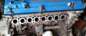
Power unit
The engine compartment is located directly inside the car, as this is due to its design.
Access to components and assemblies is also provided from the passenger compartment by removing the cover, which:
- Provided protection for the driver and passengers from the penetration of exhaust gases;
- Protected from dust and dirt;
- Served as an additional heating element (passive - from heating).
The previously used engine from Pobeda was replaced with a more modern engine from the 21st Volga. This was facilitated by the launch of a production line at the Zavolzhsky Motor Plant in 1964.
Note! Despite some skepticism regarding the inconvenience of servicing a cabover car with your own hands, years of operation have proven that there are no difficulties.
Passive vehicle safety
The design of the "Baton" with a cabover layout also initially raised a number of questions regarding safety. However, a series of crash tests conducted back in 1971 at the Dmitrov test site proved that in most emergency situations the driver and passengers of the UAZ 452 have a chance to avoid injury.
Malfunctions and repairs
- Lack of battery charging occurs when the drive belt slips due to wear or low tension. Repair consists of installing a new part and adjusting the tension. Another reason may be wear on the brush assembly, which needs to be cleaned of dirt and carbon deposits. At the same time, it is recommended to inspect and clean the collector; if there is severe wear, the surface is worn away.
- Constant overcharging of the battery occurs due to a breakdown of the voltage regulator or damage to the power circuit of the integrated unit. The burnt part is replaced with a new one.
- Low generator power occurs when the belt slips or the regulator is damaged. It is also possible that there is an interturn short circuit inside the stator windings, which will have to be replaced. It is recommended to check the functionality of the diode bridge.
- Accelerated wear of the brushes occurs when the commutator beats or the surface of the unit becomes oily. Repair consists of grinding the surface and degreasing it with gasoline.
How to check
Testing the generator is carried out using a test device that is connected to the positive terminal and the housing. The voltage should be in the range of 13.5-14.6 V.
The voltage regulator is tested using a lamp and applying increased voltage. You can thoroughly check the generator in a workshop using a special stand.
Replacing the alternator belt
The type and size of the belt depends on the engine model. For example, the ZMZ-409 injection unit uses a poly-wedge part with a length of 1220 mm. To remove the element, you need to loosen the tensioner pulley and then unscrew the generator mount. After this, the belt is removed from the pulleys and a new part is mounted.
To replace the V-belt used on carburetor engines, you need to loosen the generator. After installing the new part, tension is ensured by moving the housing along the guide bracket. It is important to align the generator and crankshaft pulleys in the same plane, which extends the life of the belt and reduces noise during operation.
«>
Device
The following devices are found on machines:
- early model G12, producing current up to 20 A;
- G250, equipped with a built-in rectifier, develops power up to 350 W;
- improved 161 3771, equipped with an integrated voltage regulator;
- brushless products model G700A30.
All generator models are mounted on the crankcase of the power unit on the right side with a special bracket. The drive uses a belt stretched between pulleys. The lower support of the generator allows the unit to be moved a short distance, providing drive tension.
- Outer casing made of light alloy or steel (on early models). At the ends there are covers in which the rolling bearings are located. The back cover on a number of models is used to install the rectifier unit, brushes and voltage regulator.
- Inside the housing there is a package of steel sheets with a wound wire that forms a 3-phase winding. A device called a stator is used to generate current.
- Inside the stator, a rotor rotates on bearings, on which steel bushings and an excitation winding are placed. The wire leads are attached to the collector. On the outside of the stator there is a shaft with a recess for a key, which is used to mount the drive pulley. The part is secured with a nut. An impeller is installed in front of the pulley to supply cooling air inside the device.
- A spring-loaded brush assembly is used to supply excitation voltage.
- The rectifier bridge consists of 6 diodes.
Period from 1965 to 1984
During this period, the automaker equipped its products with electrical components available to the domestic industry. Some of them were known for a long time, others were experimental, evidenced by previous years, and which had to prove their suitability.
Connection diagram for headlights on UAZ 452 first editions
Lighting control
In particular, the controls and a number of main units migrated from its predecessor, the GAZ-69. Thanks to this, the price of the car remained the same.
On models of the first years of production, a foot light switch was installed, which had several operating modes:
- The first position activated the circuit for switching the low beam headlights and side lights;
- In the second position, the low and high beam headlight circuit was activated.
For reference: Turning on the headlights (low or high beam) led to the turning off of the front side lights.
Foot switch for headlights and parking lights
The modernized light switch has a different operating algorithm:
- The first position supplies power to the side lights only;
- The second position is side lights and low (high) beam headlights.
Caution: This algorithm with non-switchable dimensions is a mandatory requirement for passing MOT.
The factory instructions give recommendations for reworking the old circuit, in which it is important not to mix up the contacts of the foot switch
The most correct option is to replace the old switch with a modern one, which uses only 3 contact groups.
Also, on older versions of the “452” there was no alarm, so in the electrical diagram:
- An RS-57 breaker relay was installed (mounted in the wiring gap from the “+” terminal of the battery to the direction indicator switch);
- The middle contact of the relay closed the indicator light on the instrument panel.
Ignition system
Ignition of UAZ 452 model 1968
Also on the “452” contact ignition was installed:
- The “+” wire from the battery supplied power to the ignition coil;
- From the coil, the high-voltage wire transmitted the impulse to the breaker (distributor) and further to the spark plugs.
Period from 1985 to 2013
In later modifications, with the advent of injection, some changes were made to the ignition:
- An additional resistance was installed in the “battery-ignition coil” circuit;
- A separate wire from the starter was laid to the coil wire connection terminal (past the additional resistance)
- On later models, an additional starter relay was installed in the circuit.
Control devices UAZ 452
For reference: UAZ vehicles also have different control devices. Some machines had an ammeter installed instead of a voltmeter. The UAZ 452 wiring made it possible to connect a voltmeter into the wire gap between the battery and the ignition system.
Conclusions: along with the car, the electrical circuit also changed. This factor should be taken into account when carrying out scheduled repair work in order to eliminate emergency situations.
General concept
Ignition contact diagram
in itself is not bad, because humanity has been using it since the advent of the first car. But, of course, it is far from the capabilities of contactless ignition. Therefore, many UAZ owners, in an effort to improve the performance of the power unit, reconfigure it.
And not only UAZs, but also other domestic cars, for example, a number of other brands and models are subject to alterations.
Effect of modernization
What is important is that the engine compartment and interior electrical wiring of the UAZ 31514 remains virtually unchanged, and the alteration itself is characterized by the installation of new elements under the hood.
As a result:
- The engine begins to operate stably in all modes;
- Improves cold starting;
- Fuel consumption is normalized;
- The engine power will reach the passport data.
Differences between ignition systems
The main difference between the two systems is the moment of sparking:
- In classic ignition, a slider under the distributor cover is responsible for this when it comes into contact with the output contact on the spark plug wire. In this case, the supply of a high-voltage pulse occurs with an increase. It seems to be lubricated, reducing the spark power at the spark plug electrodes.
- In contactless ignition, the switch generates a charge and releases it almost instantly
upon receiving a signal from the Hall sensor. As a result, the candle produces a more powerful spark. Among domestic off-road vehicles, Niva has a similar contactless ignition system - see.
Note! More powerful sparking promotes self-cleaning of the spark plug, because The fuel burns intensively, leaving no deposits.
Platform for conveyor models
Repair and maintenance manual for Hyundai Accent
The “Loaf”, which became famous, thanks to its all-metal body, the “452” model served as a platform for the creation of an entire line of vehicles:
- UAZ 2206 – a minibus designed for 11 people;
- UAZ 3962 – vehicle for emergency medical services;
- UAZ 396255 - a civilian modification of an ambulance for the needs of rural areas;
- UAZ 39099 – promoted under the name “Farmer”. Designed for 6 passengers and 450 kg of cargo;
- UAZ 3741 – a van for transporting 2 passengers and 850 kg of cargo;
- UAZ 3303 – an onboard vehicle with an open body;
- UAZ 3904 is a cargo-passenger version that combines the convenience of an all-metal body for passengers and an open body for cargo.
The electrical wiring of the UAZ 3909 is identical to the models 3741, 2206 and 3962
Characteristics
Despite its simplicity, the UAZ-469 already in those years had two fuel tanks and excellent cross-country ability. It was possible to overcome fords, obstacles and bad roads on this SUV without any modifications, but today tuning of various UAZs, including the 469 model, is becoming increasingly popular. Amateurs equip cars with larger wheels with mud tires, lift the car and install more powerful engines. True, with the latter option, all the simplicity of the design fades into the background, because you have to completely redo the entire electrical wiring of the cars. Nevertheless, the popularity of the car is only growing.
Two names for one model
Repair manual for VAZ 2108, 2109, 2114, 2115Device features
The thing is that from 1945 to 1966 there was an industry classification of vehicles, according to which:
- Each car plant was assigned a code consisting of capital letters of the full name;
- Car factories were assigned a certain digital range, which they could use for the models they produced.
New requirements
When a new classification of vehicles was adopted in 1966 (industry standard - OH 025270-66), the essence of which was to standardize digital designations, the process of replacing the names of existing vehicles turned out to be quite complicated:
- Due to the impossibility of simultaneously replacing all documentation;
- Due to the mentality of producers and consumers, therefore, the replacement process lasted more than 30 years.
Index decoding
The civilian version of the car “459B”, according to the new classification, received the digital index 31512, where:
- The first digit indicates the vehicle class, determined by engine displacement and vehicle weight. In relation to the model, this is the number “3” weighing up to 1.5 tons and working volume up to 2.5 liters;
- The second digit of the index indicates the type of vehicle. Number “1” – passenger car;
- The third and fourth digits of the index are assigned by the automaker. As a rule, they indicate an in-plant designation;
- The fifth digit indicates the modification. In this case, UAZ modified the “459” model, which, according to the new requirements, should be numbered as 3151. Accordingly, the modified car receives the index 31512.
Instructions for deciphering the industry standard OH 025270-66
And since the vehicle is produced and operated much longer than this period, the wiring diagram of the UAZ 31512 is identical to “459B”.
Circuit monitoring
Monitoring of the circuits of UAZ-315194 and other vehicles without turning off the voltage is carried out by a voltmeter or ammeter. The first one is connected in parallel, connecting to the section or device being tested. Measuring range “0-25”V. When manipulating, the negative wire is attached to the vehicle frame, the positive wire is attached to the user or supplier. A decrease in the effective electric field indicates a problem with the circuit system (short circuit, break, oxidation, etc.). Control is carried out with a light bulb, the power of the product does not exceed three or four W; voltage twelve V.
Testing with an ammeter is carried out with a maximum limit of not less than 10A stable current. The installation of the device is consistent with respect to the controlled product. Positive contact concerns the source, negative contact concerns the consumer. If the current value is below the required level, it indicates a malfunction of the electrical circuit; if it is higher, it indicates a consumer short-circuit.
Source