Semi-trailer braking system. Construction details
In a pneumatic braking system, the drive occurs using the energy of compressed air. The drive refers to all elements and mechanisms located between the brake and the control element, ensuring the operation of the semi-trailer braking system.
The drive is usually divided into two parts:
The drive parts do not consider the supply and control lines that connect the semi-trailer and the towing vehicles.
The control drive refers to the drive elements that operate the brakes and also control the supply of the required energy.
An energy drive is a system that supplies energy to the brakes, which is necessary for their operation and the operation of all braking mechanisms.
A brake is a mechanism in which the resulting forces counteract the movement of vehicles.
All about the repair and installation of a brake valve for KamAZ
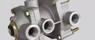
The KamAZ brake valve is a mechanism that controls the working brake systems of the vehicle.
Types of Brake Valves
Trucks, including KamAZ, operate on a braking system that uses a pneumatic drive.
According to the type of design, there are two types of brake valves:
- single-section;
- two-section.
The second type of crane is usually installed on KamAZ trucks, since they are heavy-duty.
The two-section crane can also be of several types for different car models:
- Each brake section is controlled separately;
- unified control of all sections.
The design and operating principle of these types of brake valves are the same.
Typically, KAMAZ vehicles from version 5320 are equipped with a Wabco 100-3514008 brake valve.
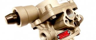
Main brake valve KAMAZ EURO
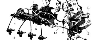
On modern trucks produced by the KamAZ company, the Euro standard State Customs Committee is installed. The structure of the main brake valve is shown in the figure below.
Semi-trailer braking system. Kinds
The brake can be of several types, depending on what causes these forces:
- Friction brake. The generation of force in it occurs due to the friction of two moving parts relative to each other. The elements of such a brake are called brake mechanisms.
- Electric brake. Force arises from the influence of electromagnets on each other without direct contact.
- Hydraulic brake. The emergence of a counteracting force occurs under the action of a fluid that is located between parts of the vehicle moving relative to each other.
- Engine brake. The origin of the force is due to the fact that the braking effect on the engine occurs through artificial interaction, which is transmitted to the wheels.
- And finally, the semi-trailer pneumatic braking system.
What is the pressure in the hydraulic brakes of passenger cars?
Initially, it makes sense to understand such concepts as pressure in the hydraulic system and the pressure exerted by calipers or cylinder rods directly on the brake pads.
The pressure in the hydraulic system of a car in all its sections is approximately the same and at its peak in the most modern cars is about 180 bar (if you count in atmospheres, then this is approximately 177 atm). In sports or civilian charged cars, this pressure can reach up to 200 bar.
Of course, it is impossible to directly create such pressure only through the effort of human muscle power. Therefore, there are two reinforcing factors in the braking system of a car.
- Pedal lever. Due to the lever, which is provided by the design of the pedal assembly, the pressure initially applied by the driver on the pedal increases by 4-8 times, depending on the make of the car.
- Vacuum booster. This unit also increases the pressure on the brake master cylinder by approximately 2 times. Although different designs of this unit provide for a rather large difference in additional force in the system.
In fact, the operating pressure in the brake system during normal vehicle operation rarely exceeds 100 atmospheres. And only during emergency braking is a well-physically developed person able to press his foot on the pedal to create pressure in the system above 100 atmospheres, but this happens only in exceptional cases.
The pressure of the caliper piston or wheel cylinders on the pads is different from the hydraulic pressure in the brake system. The principle at work here is similar to that of a manual hydraulic press, where a pump cylinder with a small cross-section pumps liquid into a cylinder with a much larger cross-section. The force increase is calculated as the ratio of the cylinder diameters
If you pay attention to the piston of the brake caliper of a passenger car, it will be several times larger in diameter than the piston of the main brake cylinder. Therefore, the pressure on the pads themselves will increase due to the difference in cylinder diameters
Pneumatic braking system for semi-trailer
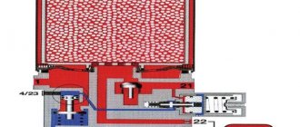
In the pneumatic braking system of a semi-trailer, the control drive is the components of the pneumatic drive itself, which transmit a signal to the controlled or automatic operation of the power drive parts. The number four on the pneumatic drive control elements (regulators, valves, brake valves, etc.) indicates the input of the pneumatic control signal. On the functional and block diagrams you can see the same meaning of this signal.
In the pneumatic braking system of a semi-trailer, the energy drive is the elements of the pneumatic drive, due to which the parts of the control drive or energy drive (pneumatic cylinders, energy accumulators, brake chambers, etc.) are supplied with compressed air. The number one on the pneumatic drive control elements indicates the input of the supply line. In some cases, the functions of the supply can be performed by a control signal. But even in this case, the input of this signal on the diagrams and elements of the pneumatic drive will be marked with the number one.
The number two on diagrams and controls always indicates any output signal.
If the control elements contain not one, but many outputs and inputs, then they are marked in ascending order from the original designation (for example: 9,10 or 18,19).
On the brake drive elements, the number three means connection with the atmosphere.
Solution
In all manuals for repairing the pneumatic brake system, if a malfunction is detected, it is recommended to replace the non-functioning unit with a new one. But this is not always the best solution to the problem. Often, a newly installed part will briefly eliminate brake release because parts of the assembly wear out after very long use. Most often, grease is required to be applied, even to the lowest layers of the assembly.
Disassembly and lubrication of a two-wire tap
This part has two pistons. Malfunction most often occurs as a result of oxidation, lack of or poor lubrication of the first or second piston.
Usually it is enough to remove the two-wire tap, disassemble it, apply grease, assemble the unit and install it back. In the vast majority of cases, nothing more needs to be done. Rarely does a piston defect (deviation in size) occur, then replacement of a part with non-standard parameters is required.
Dismantling and lubrication of the main brake valve
If there is a fitting, diagnosing brake system problems is easier. If you “pull” the fitting and the brakes “release”, then most likely you need to work on the main brake valve.
All activities come down to disassembling the unit and applying grease.
Dismantling and lubrication of the main brake valve
Piston check
In rare cases, lubrication does not guarantee normal operation of components. If, after installing the part, problems with brake release do not disappear, it is necessary to check the size and integrity of the pistons.
If possible, it is necessary to take measurements of similar parts of a suitable assembly and compare the results. There are known cases (confirmed by videos on the Internet) when the increased height of a spare part interferes with the efficiency of the mechanism. Moreover, in the new unit this is compensated by the thickness of the gasket. Over time, the material shrinks and the system begins to “fail.”
Pressure check
Control consists of establishing air pressure using measuring instruments.
Before testing, all air leaks from the pneumatic system are eliminated. Check procedure:
- Load the pneumatic system with air until the sensor warning lights turn on. The value on the pressure gauge at this moment is 620–750 kPa. The control lights ideally go out when the readings reach 450–550 kPa.
- Release the brake (the vehicle must be stationary). The pressure decreases by 50 kPa. At the same time, the pressure gauge in the line shows a pressure of 620–750 MPa, and in the air ducts connecting the tractor and the PP – 0 kPa.
- Set the parking brake parallel to the ground. The pressure gauge readings correspond to the values of the previous paragraph, only the pressure in the connection head is expected to be 480–520 kPa.
- Then move the parking brake handle perpendicular to the floor. Then the pressure in the receiver should be 670–750 kPa; in the connecting head of the two-wire drive, the pressure gauge shows the same values.
- After pressing the auxiliary brake connection button, a pressure of 60–70 kPa is established in the brake valves.
When monitoring the functionality of the pneumatic system, when the indicators drop to 450–550 kPa, warning lights and an audible buzzer in the tractor cab turn on.
Semi-trailer braking system. Operation
Let's consider the functioning of the braking system of a semi-trailer using the example of a cargo vehicle used to tow a semi-trailer.
The pneumatic drive of a semi-trailer is usually divided into several circuits that are independent of each other. This was done to ensure safety. The first circuit is the supply circuit, designed to prepare compressed air for the pneumatic system.
Compressor – is a pump for air that forces it into the supply circuit. Also performs initial pressure regulation.
The pressure regulator performs the function of maintaining the pressure of compressed air in the compressor within the required limits.
What does a dehumidifier do? Air dryer – prepares compressed air for the pneumatic system. Its main task is to remove water vapor from the air and filter unnecessary impurities, such as oil vapor. Modern dryers simultaneously perform both the function of filtering impurities and the function of regulating pressure, which is why there is no separate unit for a pressure regulator. Since many dehumidifiers operate on the principle of regeneration, they have a separate receiver for performing the regenerative function.
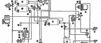
Semi-trailer braking system. Scheme
Semi-trailer braking system diagram
Semi-trailer braking system. Processes
After the compressed air passes through the dryer, it flows to the 4-circuit safety valve. What are the functions of this device? Here's what the safety valve does:
— divides the compressed air flow into different circuits;
— ensures that the circuits are filled with compressed air in a sequential order after achieving the required pressure in the primary circuit;
— when the pressure decreases or one of the circuits depressurizes, it ensures the sealing of all remaining circuits.
After air passes through the 4-circuit valve, it is distributed to the remaining circuits:
— along two circuits of the service brake system independent of each other (1 and 2);
— along the circuit of the emergency parking brake system, and along the control and supply circuits of the semi-trailer;
- along the supply circuit of the air suspension itself and other air consumers (in Fig. No. 9), such as the pneumatic hydraulic clutch, driver's seat, cabin air suspension.
This is how a semi-trailer braking system works on a semi-trailer. To perform the function of influencing the braking system, there are actuators on each circuit, and for connection with the supply and control lines of the tractor, connecting heads are located on the circuit of the semi-trailer braking system.
In the first and second circuits of the semi-trailer brake system, the air, passing through the receivers, goes to the brake valve in the lower and upper sections. Inside this element, either a combined (supplying and at the same time controlling) or only a control signal is formed, which is transmitted immediately (we look at the image of the front wheel brakes), or passes first through the control elements (we look at the image of the rear wheel brakes) to the actuating elements of the brake system ( 20 and 14). Brake force regulators, relay accelerator valves can also act as additional control elements that ensure the operation of brake release valves, accelerator valves, etc. Brake chambers combined with an energy accumulator, or simple diaphragm brake chambers can serve as actuating elements.
In the third circuit, the air approaches the hand brake valve of the parking and emergency brake mechanisms, where usually the formation of a control signal goes to the 17th accelerator valve of the emergency brake system, where pressure is released or supplied from the brake combined chamber, from the energy accumulator section. The power supply to the valve that controls the brake mechanism of the semi-trailer also comes from this circuit. This valve supplies air to the brake mechanism of the semi-trailer through the connecting heads, and it also generates a control signal that comes from the brake valves of the parking, service and emergency brake systems.
To monitor the entire braking system of a semi-trailer, measuring instruments are attached to it. This is either one common monometer for everyone, or several monometers measuring pressure in the first and second circuits. There are also control lights to signal changes in pressure in the pneumatic drive.
The tractor has ABS (anti-lock braking system) components connected to the pneumatic system, which implement this function for the entire vehicle. The system contains sensors that analyze the angular speed of the wheels, modulators (electromagnetic valves) that perform the function of actuators, a control unit for analyzing sensor signals, diagnostic and control lamps that transmit a signal about those conditions, and a semi-trailer connecting plug.
The semi-trailer is supplied with compressed air through a red connection head. Air is forced into the receiver, passing through the filter and through the brake valve.
Brake force regulator
A control signal passes through the yellow connection head, which reaches the brake valve of the semi-trailer, passing through a filter. This signal generates a control output signal in this tap, which is then adjusted by brake force regulators depending on how loaded the vehicle is.
On semi-trailers with central axles, only one such regulator is installed. In semi-trailers where the axles are staggered, a special valve may be present to ensure even air distribution and maintain equal pressure between these axles.
This adjusted control signal is suitable for ABS modulators. These modulators on semi-trailers can also act as accelerator valves. One modulator on a semi-trailer, to comply with standards and depending on how the system is designed, can energize the actuators of the axles of one or several wheels along one of the sides of the semi-trailer.
Further, in modulators, the control signal becomes a signal that actuates the actuators. Sometimes on semi-trailers, brake chambers with energy accumulators are used as actuating elements. The air supply to its sections is carried out using another pneumatic line.
In a semi-trailer, ABS elements consist of:
— pressure modulators that have the function of an accelerator valve.
To check the correct operation of the entire system, there is a diagnostic connector, and so that the system is supplied with electricity and receives control signals from the tractor, there is a connecting plug.
The braking system of a semi-trailer, although complex at first glance, but once you understand the principles of its operation, you will learn to understand where exactly the braking system of a semi-trailer has failed.
Schmitz. Replacing the electronic brake valve with a simple one.
According to the registration certificate it was an '08 and looked very good except for the tires. It was only distinguished by sharp braking. To this question, the former owner explained the following. The semi-trailer has ABS and you need to supply 24 volts to the second transfer. However, I went like that. In a word, you'll get used to it. After a while, air began to hiss from the electronic brake valve. I again consulted with the previous owner, who said that this cuff flies every three months, and there is nothing difficult about replacing it.
Now I began to ask pneumatic specialists what to do next. I contacted a specialist and heard a sad answer from him. The tap is 10 years old and the well through which the cuff works has already been removed and the tap needs to be radically changed, of course.
Changing simple faucets that cost five ten thousand is not a problem, but this electronic one costs fifty thousand. In addition, it still needs to be registered and a converter from 12 volts to 24 volts must be installed from the machine to power it. At first, I was going to buy this ill-fated tap. Later, after a reasonable assessment, I decided that it didn’t make sense to give 60,000 rubles and could simply convert the brake valve to a simple one and buy an additional submarine and three accelerator valves.
Three months later, with the onset of frost, not so far from the house, the tap finally hissed. I spent about two hours trying to power four energy accumulators in addition to the tap. Finally, the air pumped up and the pillows rose and I slowly set off home, thinking about buying a faucet. But as you know, trouble doesn’t come alone and the last left wheel on the semi-trailer exploded. Out of habit, I wasn’t very upset, because in life anything can happen. I replaced the wheel and decided to pump it up. But it was not there. I started to figure out a problem that I didn’t pay attention to while parked. The exploding wheel tore off the mudguard, broke off the semi-trailer's brake release coin and broke off the handle of the floor level control valve. After turning off several pipes I made it home.
The next day I went to the store. The store smiled and said that you were not the first. Regarding prevention, they suggested that the newest wheel should be on the left rear and then there will be no problems. What I heard was not at all pleasing. Crane 58,000 rubles, brake release valve at least 12,000 rubles and floor level tap 8,000 rubles, plus a wheel at least 18,000 rubles. I mumbled in a whisper and began to lean towards the idea that this damn disc semi-trailer was a good bomb for the owner. The truth remains that the flatbed semi-trailer is a lifesaver. I went to work with him. A week later I bought a simple semi-trailer crane, a submarine and three accelerating cranes. He dismantled the old electronic crane and began installing the purchased cranes with the expectation that in a critical situation (it is unknown what our legislators will do) it would be possible to restore the original braking system.
Of course, I fiddled around for two days and three more times I chased around for the missing fittings. The automatic floor level control was engaged directly, and the brake release valve was turned off. After leaving, I didn’t recognize my cart. She braked softly, the wheels did not skid either when the cart was loaded or when it was empty. The only thing after a while is to check the pressure in the pneumatic chambers on an empty cart. Recently I was told that on an empty cart the pressure in the brake chamber should be four atmospheres.
To date, the semi-trailer has covered approximately 200,000 km and required the replacement of one brake valve.
Short description
The trailer brake control valve consists of the following elements:
- Pair control valve and similar single element.
- Two isolation valves.
- A pair of connection heads.
The valve is responsible for controlling the brakes of the semi-trailer, directing compressed air from the input source to subsequent consumers, working both synchronously and separately. A command is sent to two outputs to increase the pressure in the line, and one analogue receives the opposite action, affecting a decrease in pressure when releasing the air mixture using a hand lever.
Control valve
The trailer brake control valve is equipped with a main valve, which consists of three sections, a large and small piston with springs. The middle piston element has an inlet valve that presses the spring against the seat.
The remaining components of the part in question:
- Diaphragm.
- Discharge hole.
- Stock.
- Adjustment screw.
In the released position, compressed air is constantly supplied to the output parts. It acts on the diaphragm and piston, holding it together with the rod in the lower position. This is facilitated by the increased diaphragm area. At the top, the piston group is located in the uppermost position, and the exhaust valve is separated from the seat. The inlet analogue is in a closed state under the influence of a spring. One of the leads connects the brake control line to the atmospheric outlet using relief holes and a rod.
SSU elements
The fifth wheel of a truck consists of several elements. Manufacturers offer SSU in the following configuration:
- Detachable coupling device. Operating principle: when braking and increasing speed, it takes on the load of the truck and performs the functions of turns. The greatest safety is found in elements with one fastener grip.
- Support plate. The plate is the basis for fixing the finger. The cast metal structure has the required rigidity.
- Fastening elements. The hitch part is secured to the tractor frame. The elements are classified into two groups: mounting tiles and corner tiles. The parts have different sizes.
When brake systems transmit traction forces to the base plate, the pin is in a state of unloading from longitudinally acting loads. And due to the gripping of the part along the upper chord, the bending moments on the king pin are reduced.
Valve operation during braking
The valve of the KamAZ trailer brake control valve supplies compressed air from the sections of the device to the terminals when braking. From the other outlet of the air tank, the compressed mixture flows to the control terminal, after which it is sent to the main part. There, the air acts on the piston until it is balanced at the bottom under the upper pressure. The upper piston operates under the force of air pressure and spring. In this case, the middle piston must also be balanced under the influence of identical factors. In principle, a general tracking action occurs.
When the brakes are released, compressed air is discharged through the atmospheric opening of the valve from the filled compartments. The pistons, under the pressure of the spring and the air mixture, move to the upper position, and the rod with the piston moves down. The valve comes off the seat and connects the internal and external inlet.
Suitable compressed air causes the rod and piston to move separately upward, and the large and small piston element downward. Subsequent operation of the brakes follows a similar principle.
When the truck's backup or parking system is activated, compressed air is drawn through the atmospheric port in the manual return valve and released to the outside. The degree of pressure above the diaphragm decreases, reducing the force on the working elements. The seat rests on the valve, separating the outlet from the atmosphere. Then the valve opens, communicating between the outlet and the main line.
Compressor
This pneumatic drive element supplies compressed air to the system. It is processed in a purifier and then transported to tanks. The release of the air mixture from the cylinders is prevented by a check valve. The pressure indicator is determined by a pressure gauge. After activating the brake pedal, air enters the brake compartments through the opened valve, as a result of which the compression of the pads is triggered. The reverse process occurs using tension springs.
The compressor design includes a cylinder block, its head, crankcase, and locking covers. The crankshaft of the mechanism rotates in ball-type bearings and interacts with the pistons using pins and connecting rods. The front part of the crankshaft is equipped with a V-belt, oil seal and key. A fan is provided as a cooler. In the cylinder head above each working element there is a plug with a spring and a discharge valve. The lower connecting rod heads are equipped with shims.
Peculiarities
In the trailer brake control valve, the main pressure is built up until the force acting on the piston from below is equal to the force applied to the diaphragm. This ensures follow-up operation of the valve.
When the compressed air mixture simultaneously approaches the working terminals, and the pressure in the compartment connected to the main line, and the pressure value exceeds the same value in the control terminal (20-100 kPa), the brakes act proactively. The required pressure value is adjusted using the adjusting screw by tightening or unscrewing it.
Single safety valve
This element serves to maintain pressure in the air tank of the tractor in the event of a critical decrease in this indicator in the supply line of the semi-trailer. In addition, it prevents the leakage of compressed air from the system during an emergency decrease in pressure in the vehicle drive, which helps prevent unauthorized braking of the towbar.
The single valve is adjusted to bypass air when the outlet pressure reaches 550 Pa. The compressed mixture enters through the outlet into the working niche under the diaphragm, then into the cavity in front of the valve. From there it goes to the exit of the main highway. The required pressure value is adjusted using the adjusting screw.
Isolation valve
This part is involved in the operation of the trailer brake control valve as follows:
- If necessary, it closes the pneumatic line connecting the tractor with the towbar.
- If you install the handle of the device along the axis of the valve, the pusher with the rod will be in the lower position and the valve will be open. Air in a compressed state through it and the corresponding outlet is directed from the car to the semi-trailer.
- When the handle is placed across the frame, the rod and diaphragm move upward under the influence of air pressure and spring. The valve blocks the leads by sitting in the seat. The air mixture flows from the connecting system into the atmosphere, which makes it possible to disconnect the connecting heads.
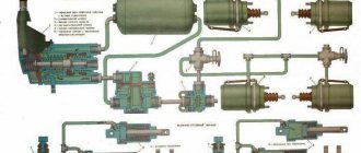
Below is a schematic representation of the crane, as well as the main symbols and components.
- a – the device is not active;
- b - position of the open tap;
- 1—output to the tractor air cylinder control valve through a single safety valve;
- II - Main outlet of the trailer brake system;
- III - atmospheric output;
- 1 - spring mechanism;
- 2 - valve;
- 3 — diaphragm with rod;
- 4 — return spring;
- 5 - pusher with handle.
Single wire system
Unlike the two-wire trailer brake control valve, this design consists of a control valve, a disconnecting analogue and an L-shaped connecting head.
The single-line actuator brake control valve operates through a single line that serves as a supply and control system. It is worth noting that the valve functions to reduce pressure in the main line, with the ability to bring the indicator to the atmospheric parameter. As the pressure decreases, the intensity of the towbar braking increases. Other parts of the valve include: pusher with diaphragm, step type piston, valves (inlet and outlet). They are aggregated between themselves by means of a connecting rod. There is also a lower piston.
Working in a disinhibited state
In the inactive position, air in compressed form flows from the parking brake system cylinder to the outlet, which is connected to the atmosphere via a control valve. Under the influence of the power spring, the diaphragm and pusher are located in the lower position. The exhaust valve remains closed, while the intake valve operates open, allowing air to flow to an outlet that connects to the single-line brake control line.
Synchronously compressed air is supplied to special cavities, the pressure in which remains equal. Taking into account the fact that the area of the stepped piston is larger, it moves upward until it stops. When the pressure in the trailer brake line chamber reaches about 500-520 Pa, the lower piston goes down and blocks the inlet valve. When the brakes are released, the system automatically maintains a pressure level of 500 Pa, which is slightly lower than the same parameter in the pneumatic drive of a truck.
Saddle Maintenance
The condition of the “fifth wheel” is monitored at least 2-3 times a month. Frequent inspection will prolong the performance of the SSU. Therefore they recommend:
- Assess the reliability of the springs attaching the grips to the locking knuckle.
- Periodically, the stove needs to be treated with oil.
Should it be regulated?
Adjusting the saddle on a tractor is one of the conditions for maintaining the functionality of the mechanism. During transportation, the saddle wears out quickly. It is impossible to determine the correct operation of the stove visually, so you need to know some of the reasons and a list of common breakdowns of truck components. A characteristic sign for adjustment is the appearance of a knocking sound when the road train stops and moves.
Eliminating Gaps
The vertical power supports of the tractor are not always subject to deflection under the influence of high load pressure on the frame. During turns, a lot of pressure is applied to the saddle in a perpendicular direction, which greatly injures the upper part of the plate, on the surface of which small gaps form. During operation, the coupling pin wears out quickly. This part requires separate repairs from specialists.
York and Jost seat clearances are eliminated by pressing the locking wedges against the king pin. Manipulations to remove gaps are carried out using a screw control or an automatic metal spring.
How does the system function when braking?
When the tractor brakes are activated, compressed air from the double-circuit valve flows to the valve of the single-line valve for controlling the brakes of the MAZ trailer. The mixture fills the plane under the diaphragm. After overcoming the spring force, the diaphragm moves upward along with the pusher, the intake valve closes, and the exhaust element opens. The air escapes into the atmosphere, bypassing a special outlet, a pusher and a hole in the cover.
The stepped piston performs a follower action. If the pressure at the outlet and in the cavity decreases, the force on the piston from below also decreases. In the upper part, this element is subjected to pressure from the corresponding cavity, identical to the force in the second compartment. The hub, in turn, receives force from the first cavity. As a result, due to the pressure difference, the piston moves downward, dragging with it the pusher, which closes the outlet window with its seat. The subsequent increase in pressure causes the complete release of the air mixture from the main brake structure of the semi-trailer. The pusher is in the lowest position, the inlet window is blocked, and the outlet element is open.
Brake force regulator!
Brake force regulator! ⇐ Mutual assistance on the road, hotline
- print version
- 1
- Quote
- Quote
Posted by successful » 16 Dec 2015, 01:23
The problem is in the energy storage unit.
Operation of the energy accumulator when using the parking brake: https://www.youtube.com/watch?v=4kOVYhu8f1M
Pneumatic connectors of the energy accumulator: 12 — part of the parking brake (“handbrake”) 11 — part of the service brake (brake pedal)
The video shows that when the handbrake is removed, air is supplied to connector 12, but the service brake is not pressed at this moment and, accordingly, the regulator is in the position of releasing air from the brake chambers of the energy accumulator (connector 11). Both chambers are separated by a seal along a thick rod inside the energy accumulator, when the seal allows air to flow from the “manual” chamber to the brake chamber when the brake is released.
Replacement or professional repair of energy accumulator.
- Quote
- Quote
Post by successful » 16 Dec 2015, 18:52
- Quote
- Quote
Post by successful » Dec 21, 2015, 04:04 pm
- Quote
Post by successful » Dec 21, 2015, 10:52 pm
- Quote
- Quote
Good afternoon! I defeated him, it turned out to be simple, the circle with the rubber ring numbered 6 of the repair kit 9730110002 (I don’t know exactly what it’s called) didn’t come back well, when I took it apart the first time it went better and I smeared it from another non-original one repair kit with red grease (-40 +100) and when I took it apart again to replace the original cuff, this circle turned out to be glued and did not come back, thereby preventing the cuff from closing completely, I could barely pry it out from there, I thought I would break it, in the end I washed it all and smeared it with grease Vabko from the repair kit checked that everything moved easily, assembled, installed and Hurray everything works. Thank you so much for the advice, it helped! But there are a couple more questions.
1. How should I lubricate the taps to prevent them from sticking and freezing in cold weather?
2. All the air leaves overnight, there are no leaks from the outside anywhere, I suspect a 4-circuit safety valve (934.714.130.0 replacement for WABCO 934.714.730.0), I realized when I had to unscrew the tubes from the compressor to the dryer in the summer, first I unscrewed them then I screwed it on, but they were all bent and everything turned out crooked, when I started to unscrew everything again to align it, air began to come out of the tubes, if this is because of it, then tell me the number of the repair kit, otherwise the store again said take a new one and don’t think about it. On the bottom of the valve (the cover with the valves) there is another number (934 713 655 6) I scoured the Internet and did not find accurate information, but from the photos I saw that the same cover is on the 4-circuit valve from Volvo (934 714 140 0 ), maybe it will work for him. Thank you very much for your answer
Variable mode
Connecting the trailer brake control valve implies normal operation of all components of the device. The single-wire version, when the tractor brakes are released, interacts with the atmosphere through the provided opening of the two-wire drive valve. The pressure in the working cavity decreases, and the diaphragm with the pusher moves to its original position, blocking the outlet valve and opening the inlet element. The compressed air enters the terminal and connecting system of the trailer, releasing it.
The L-shaped coupling head aggregates with the single-wire drive line, automatically closing the truck's coupling system in the event of spontaneous disconnection of the heads, which can happen when uncoupling a trailer. The head is equipped with a valve, locked by spring action in the disconnected element, and opened in the connected head by means of a pin.
Wabco Trailer Brake Control Valve
It is these structures that are equipped with trailers connected to MAN, DAF, and Volvo vehicles. There are several modifications of cranes. Let's consider the features of the unit with the ability to set advance.
The working braking of the unit consists of supplying air through the connection head. Power passes through the tap outlet to the semi-trailer receiver. Synchronously, the piston, under spring pressure, moves down along with the valve. Opening the outlet that connects to the working leads. After the tractor brakes are activated, the compressed air mixture flows through the connecting head into the piston chamber.
After closing the outlet, the MAN trailer brake control valve supplies air from the receiver through the outlets to the cylinders. At the same time, the mixture enters a special chamber and creates a force on the valve. After the maximum pressure is built up, the valve opens to meet the compression of the spring. As a result, air enters the storage compartment, loading the lower part of the piston. After the summed pressure in all chambers reaches the set limit, the piston moves upward.
Lubrication and cooling
The pneumatic brake drive has a combined lubrication system. Oil is supplied from the main line through a pipe to the inside of the crankshaft. The connecting rod bearings are placed in an antifriction solution and are forcibly lubricated. The remaining elements receive oil by spraying. The waste from the crankcase is sent to the engine tank through a special outlet.
The cooling system of the pneumatic drive compressor is liquid type. It is connected to a similar unit of the power unit. When one of the pistons moves to the bottom position, a vacuum is created and air enters it through the cleaner and the intake valve. After the piston rises, the air mixture is compressed, then it flows through the valve into the cylinders and the main system. Then the whole process is repeated.
The air pressure indicator is limited by a special regulator, which reduces the cost of motor power to drive the compressor, which increases the operating life of the unit. The design with the regulator is located under the valves and contains a pair of plungers and seals with pushers. The plunger rocker arm is connected by a spring, the cavity under the intake valves is connected to the purifier pipeline, and the plunger channel is connected to the pressure controller.
Automatic braking
When the supply line ruptures, the Volvo trailer brake control valve receives a sharp drop in pressure, as a result of which the load on the piston is removed. Under the force of the spring, the piston moves upward, and the valve closes the outlet. The piston part with further movement releases the inlet window.
Through the outlets, the pressure from the receivers is fully supplied to the brake cylinders. If the line breaks, the DAF trailer brake control valve operates according to a similar scheme as described above. This is due to the fact that the pressure in the supply structure of the crane also decreases due to leakage of the unit after the tractor starts braking.
Repair work
Disassembling, replacing or repairing the brake cylinder of a VAZ car is not particularly difficult. Having purchased the necessary repair kit for the working brake cylinder, unscrew the wheel and, having disconnected the pipes, remove the faulty cylinder (the dismantling diagram will be described in more detail below). For convenience, by holding the body in a vice and removing the boot, we gain access to the retaining ring that secures the piston, after removing which we remove all the working parts.
After disassembling the housing, you need to rinse everything with brake fluid and inspect the housing mirror for mechanical damage.If no damage is found, then open the repair kit for the working brake cylinder and replace the faulty parts.
Malfunctions
There are a number of problems that can reduce the effectiveness of your brakes. A trailer brake control valve repair kit may be needed in the following cases:
- After disconnecting the heads in the main line and opening the isolation valve, air from it does not flow to the tractor.
- When the disconnect valve is open, the air mixture flows from the head into the tractor line, but after connecting the elements of the tractor and the trailer distributor, the flow stops.
- When the brakes are activated, the brakes on the vehicle work, but the brakes on the semi-trailer do not.
- In the case when air comes out of the head during braking.
- During the release of the brakes, the wheels of the tractor react, but remain in a braked state on the towbar.
Inertial
Now I will try to explain why a trailer equipped with an inertia brake is the best option. To do this, let's look at the principle of operation.
Everything here is quite simple, if you don’t go into details:
- the car moves and pulls a trailer;
- when braking, it is necessary to brake the car itself and the towed vehicle;
- inertia forces the trailer to move even if the vehicle stops;
- load is applied to the coupling device;
- the trailer brake control unit is located in this area;
- this block, taking into account the load, activates the braking elements;
- the stronger the inertia load, the stronger the braking force generated;
- When the trailer stops putting pressure on the vehicle through the hitch, the brake is released.
The price of such equipment also depends on what type of inertial system is used.
There are two types in total. Namely:
It is worth talking about each of them in more detail in order to understand the difference and essence of each of the presented options.
Mechanical
The key disadvantage, which is noted by the manufacturers themselves and direct users, is the lack of the necessary tightness in such systems. And since the system is not closed, it can quickly collapse and become unusable due to water, dirt and other delights of the roads. To maintain the functionality of a mechanical unit, you need to constantly clean and care for the elements.
If you ignore this recommendation, it will not lead to anything good. Soon the driver will be faced with corrosion processes. And therefore the entire braking system will go to the landfill.
Such units are still actively installed on trailers, and not from the worst companies. The issue here is more about cost, since many buyers want to have a trailer, but they cannot spend money on really good equipment. Or they just feel sorry for finances.
Hydraulic
If you take a passenger car trailer that is equipped with a braking system, then the best choice would be a hydraulic inertia brake. And now I’ll explain why I think so.
Such units are more reliable and durable. This is largely due to their tightness. Care is needed, but periodic and outrageously simple. You won’t have to clean anything or use toothbrushes.
Hydraulics are recommended for use in situations where you have to transport boats, boats or the same jet skis. This can be explained by the good resistance of such systems to frequent contact with water. After all, when unloading a jet ski, you have to completely immerse the trailer in the water. Regular mechanical brakes won't handle this.
What exactly to choose, everyone must decide for themselves. But what you definitely shouldn’t do is skimp on the quality of braking equipment.
25,00
Subscribe to updates and receive articles by email!
We guarantee: no spam, only new articles once a week!
Experienced drivers recommend purchasing a trailer equipped with its own braking system, especially if there is a need to regularly transport heavy loads. However, if you have already bought a towed platform that is not equipped with such equipment, and you are not afraid of the need to draw up documents for changes in the design of a non-self-propelled vehicle, you can figure out how to make brakes for a passenger trailer with your own hands.
Of course, when you have a trailer for a car, you save a lot on transporting any cargo: from personal belongings and furniture to construction materials and consignments for retail outlets. It depends on the specifics of your trips. In any case, a trailer platform for a car is a useful and profitable thing.
The design of a passenger trailer is designed in such a way that the wheels of the towed vehicle operate independently of the wheels of the car
This is important for traveling with a load on country roads and on uneven ground, off-road. Under these conditions, many drivers try to at least install the overrun brake for the trailer with their own hands, since there is no factory equipment
Otherwise, there are serious risks of accidents and accidents, the inability to brake when driving downhill and other dangerous situations.
If a driver decides to install a brake system on an existing trailer, they are usually looking at a unit that can be removed from an old vehicle and slightly modified for use in a new design.