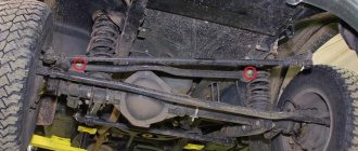
The MTZ-82 mini-tractor has established itself as a reliable, easy-to-use and easy-to-repair model. The design of the MTZ-82 front axle ensures the functionality of the model due to high ground clearance and variable track width. For smooth operation, regular preventive maintenance is necessary, because heavy loads can lead to premature wear and failure of the front axle. The rear axle also needs preventive maintenance, despite the lower load.
Design of FDA MTZ-82
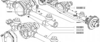
The MTZ-82 front axle ensures the transmission of torque from the engine to the steered front wheels. The front axle mechanism consists of the following parts:
Front axle design MTZ-82
- main central gear;
- limited slip differential;
- wheel reducers;
- beam structure.
The center gear includes a set of bevel gears with spiral teeth. They increase torque, providing the required power. The power is regulated by the power lever.
The differential kit includes an axle, driven and drive gears, and two satellites. It is equipped with an automatic self-locking mechanism when the FDA is turned on.
Wheel bevel gearboxes transmit torque to the drive wheels from the differential. They contact the front axle sleeves through a telescopic connection. The telescopic connection makes it possible to continuously adjust the front wheel track at the same intervals as the rear wheels. The bevel gears of the gearbox significantly increase the rotation angle. The amount of reduction in the turning radius and the ground clearance value depend on the gear mechanism.
Torque from the transfer case is transmitted to the FDA by a cardan drive. The cardan drive includes an intermediate and front cardan shaft and an intermediate support.
The central gear, FDA drive and differential are placed inside the beam.
Dispenser device
The unit is made in a separate cast iron housing in the form of a single-stage gearbox with spur gears and an overrunning clutch. The mechanism receives its drive from the secondary shaft of the gearbox through an intermediate gear mounted on an axis in the gearbox bulkhead. The mechanism is lubricated by spraying oil from the general capacity of the tractor transmission.
The mechanism includes:
- shaft rotating on two ball bearings
- single-acting overrunning roller freewheel clutch, consisting of outer and inner races
- gear coupling with a sliding block for selecting the FDA operating mode
- a control mechanism that allows you to disable - enable and block the freewheel
Overrunning clutch
The outer race 5, being the leading part of the coupling, with its outer ring gear is constantly in mesh with the intermediate gear 12 in the gearbox and receives rotation in all gears. The cage rests on two bearings 7 mounted on the outer diameter of the driven part 6 of the coupling, which, in turn, rotates independently on the transfer case shaft 8, resting on a brass bushing. Thus, both clips rotate independently of each other when unlocked. In eight profile grooves 10 of the leading part of the coupling there are locking rollers with pins 9 and springs 11, which are locked with plugs. To connect to gear block 2 when switching FDA operating modes, the driving and driven parts of the coupling have internal gear rims.
For reference! MTZ 82 transfer case bearing numbers:
- a 306K5 ball bearing is installed on the shaft on the flange shank side
- on the shaft of the reverse side of the unit - ball bearing 305A
- a pair of identical ball bearings between the driven and driving parts of the overrunning mechanism - 115K5
- a pair of tapered roller bearings 7306A on the axis of rotation of the intermediate gear of the transfer case drive in the gearbox
Mode shift clutch
The gear coupling is a single gear block sliding along the shaft splines with external gears of the same name to interact with the driven and driving races of the overrunning clutch. The choice of block position determines the operating mode of the front axle. The control mechanism is a system of rods from the control lever connected to an axis in the unit body, which moves the fork interacting through an annular groove in the gear block.
For reference! The MTZ 52 transfer case differs from the MTZ 82 tractor unit in the absence of a freewheel shutdown mode. The MTZ 82 transfer case can be installed on the 52nd - on the contrary, it is not recommended.
Breather PVM MTZ-82
Breather SU 1/8-A
The design of the MTZ-82 front axle includes a friction block, which includes a breather and a stop.
The function of the breather is to maintain the operating pressure level in the area of the main gear and beam. On the front drive axle MTZ-82, the breather is used with an adapter. The clamp used has small dimensions. The gasket is placed in the central part of the gearbox. The breather is complemented by a long tube that closes under the gearbox. Bearings are installed above and below the housing. The glasses are placed under the bearings.
The SU 1/8-A breather is designed for high loads. Its body has reliable protection. The breather consists of three discs. The transmitting torque to the regulator comes from the shaft. Threaded type linings are used under the discs.
At the top of the part there are wide clamps fixed with screws. The cuffs with adapters are fixed on special rubber gaskets.
Periodic lubrication of the part is necessary.
Operating modes
On an ongoing basis, on dirt roads in rural areas, they use the automatic mode of operation of the front axle. To reduce the wear of assembly parts in field work conditions as part of land-cultivating units - plowing, cultivation, it is advisable to use the forced operating mode of the FDA. In conditions of constant driving on roads with hard, dry surfaces, it is recommended to disable the front axle drive.
Front axle control
The control lever is located on the right side of the driver's seat and is connected to a rod passing through the cabin floor. The control handle has three positions:
- medium - automatic mode is enabled
- lower - front axle is turned off
- upper — FDA is engaged in forced mode
In later versions of the tractor, control is carried out by a lever, in older versions by changing the position of the handle.
Automatic switching on
In automatic mode, the transfer case transmits rotation only when slipping of the rear drive wheels occurs. In this case, by selecting the position of the control lever, the block sliding along the shaft splines engages its smaller ring gear only with the driven race of the overrunning clutch. This ensures that both parts of the overrunning clutch rotate independently in the unlocked position. The power transmission is switched on due to the jamming of the rollers in the grooves and the connection of both cages when the speed of rotation of the driven cage of the mechanism slows down relative to the speed of the constantly rotating driving part of the transfer case clutch.
The gear ratios of the mechanism are designed so that the driven race of the roller clutch, receiving rotation from the passive rolling of the front wheels of the tractor, rotates 6% faster than the driving race of the mechanism. Thus, during standard tractor movement, the clutch does not engage and torque is not transmitted to the front axle from the gearbox. When the movement of the front wheels naturally slows down as a result of slipping of the rear drive wheels, the rotation speed transmitted to the driven race of the overrunning mechanism decreases, but the speed of the drive gear remains unchanged. At the moment the rotation speeds of both parts of the mechanism are equalized, the rollers enter the wedge grooves, causing the parts to rotate as one whole. From the moment of actuation, power is transferred to the wheels of the front axle of the tractor until the rear wheels stop slipping. When the rotation speed of the driven cage increases due to the reverse rotation received from the front wheels, the rollers will come out of the grooves and the clutch will automatically disengage.
Forced mode
It is activated by introducing the engagement of the toothed sliding block with both the inner gear rims of the outer drive and inner driven races of the overrunning clutch. By connecting the three parts of the mechanism, a single rigid block is formed, which receives rotation from the intermediate gear in the gearbox with subsequent transmission through the flanged shank of the transfer shaft to the FDA cardan drive. This inclusion ensures constant power transfer to the front axle.
Disabling FDA
When selecting a position where the gear block disengages from both rims of the two parts of the overrunning clutch, the FDA drive is completely disconnected. In this case, the driving and driven parts of the overrunning mechanism and the gear block rotate independently of each other, that is, the automatic and forced modes are disabled.
Vertical FDA shaft
The front axle diagram of the MTZ-82 tractor includes a drive gearbox. The vertical shaft of the model is attached directly to the gearbox.
MTZ-82 gearbox design
The vertical shaft ensures the rotation of the gear, connecting to it with a splined shank. This design, according to experts, is capable of generating high speeds. The thickness of the shaft at its lower end is 45 mm. The flange of the model includes an adjusting adapter. The glass is selected to be small in size. The seal under the shaft base is not used. The design provides an overlay at the top of the part.
If it becomes necessary to remove the shaft yourself, it can be disconnected without removing the gearbox using a screw wrench. The tube is unscrewed by hand.
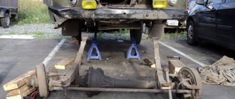
If there is a need for inspection, check the front axle first. The thrust rollers and flange should be inspected periodically. If a crack appears on the housing, cleaning is required, as well as lubrication of the running gears with machine oil. The flange also needs careful periodic cleaning.
Repair and adjustment of final drives
During operation, the FDA final drive gearbox mechanisms are not adjusted. Full adjustment of the clearances in the bearings and the engagement of gear pairs is carried out during the assembly process of the unit during repairs.
Adjusting the clearance in the rotation bearings of the upper conical pair
The axial clearance in the axle bearings on the upper part is adjusted by tightening the clamp nut. Initially, the nut is tightened until the bearing races rotate tightly. When tightening, rotate the outer races so that the rollers take their correct place. Afterwards, the nut is loosened just enough so that the bearing races begin to rotate freely and the clearance in the bearing does not exceed 0.1 mm. Although the new adjustment recommendations indicate that the bearings are installed with a preload in the range of 0.05-0.15 mm. This requirement exists and gives the advantage of increased service life before unacceptable play appears in the bearings. After adjustment, the hook is fixed by punching.
Checking the axial clearance of the vertical shaft bearings
An important point in setting is the strict position of the spacer ring between the outer races of a pair of bearings, without protruding beyond the outer edges. Otherwise, the protruding ring will prevent the shaft from being pressed into the seat.
Adjusting the engagement of the upper bevel gear pair
Adjustment of the lateral clearance in the engagement of the upper pair is carried out only by shifting the position of the vertical shaft using split gaskets 3 installed between the flange of the gear pair housing and the pin tube cup. The position of the axle shaft does not change. Normal side clearance should be in the range of 0.1-0.55 mm.
Installing a package of plates when adjusting the engagement of the upper conical pair
The gearing adjustment is checked by first removing the lubricant from the pair housing and locking the vertical shaft. Install a lead plate between the gear teeth and rotate the axle shaft from the main drive cardan mounting flange. The depth of the dents will indicate the actual clearance in the engagement. After setting the gap, check the contact patch in the engagement.
It is important to ensure that when installing horizontal and vertical shafts into the seats, the locking pins holding the shafts in the seats do not touch the bearing cages.
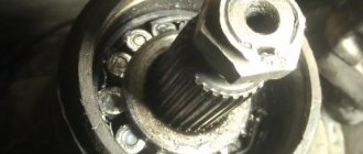
Adjusting wheel bearings
Old reference books indicate an installation gap in tapered wheel flange bearings of 0.2 mm; later operating instructions indicate that the bearings are adjusted with an interference fit of 0.1 mm. Adjustment is carried out by selecting the width of the rings installed between the inner races of the bearings on the flange shaft. With proper adjustment of the bearings, the service life before gaps of up to 0.4 mm appear can be up to 5000-6000 hours. Therefore, adjustments are made when repairing the wheel gearbox. If the backlash appears prematurely, it is necessary to inspect the gearbox and eliminate the backlash.
Installing adjusting rings for bevel gear wheel bearings
Checking the axial clearance in the tapered bearings of the wheel flange with an indicator
The operation is carried out in the following order:
- Remove the wheel from the mounting flange, drain the lubricant from the gearbox, disconnect the cover from the gearbox housing and dismantle it along with the driven gear of the wheel drive and the flanged shaft with the bearing assembly.
- Initially, you need to try to eliminate the play by tightening the fastening bolts at the end of the shaft. If tightening does not produce results, then the bearing assembly is completely disassembled and the width of the spacer rings is reduced by grinding by the amount of play.
- Afterwards, the bearing assembly is assembled and the mounting end bolts on the shaft are tightened. During assembly, it is important to check that the ends of the rings between the bearings are in strict contact with the inner races and do not rest against the cages.
- After checking the established gap, the fastening bolts are fixed with a bending plate.
When diagnosing the bearing part of a wheel reducer, you need to keep in mind that in the factory configuration of the wheel reducer, the width of one adjusting ring between the bearings is 7 mm, and the sum of the two rings is 14 mm. The overall smaller width of the rings indicates that the bearings have already been adjusted earlier and their service life is incomplete.
Adjusting the gear mesh of the lower bevel pair
The adjustment is carried out by moving the driven gear using split adjusting plates installed in a package between the gear housing cover and the flange of the bearing unit cup or in more modern versions of the unit between the cover and the gear housing. The lateral clearance of the new pair of gears is set within 0.26-0.65 mm. This value corresponds to the angular displacement of the wheel mounting flange at the radius of the bolt mounting. To check the gap, stop the drive gear of the lower pair.
Adjusting the clearance in the engagement of the lower bevel pair of the final drive
Checking the gap in the engagement of the upper and lower conical pairs with an indicator
Replacing the liner and side pivot pipe
When the pin and sleeve are sufficiently worn out, a runout occurs, affecting the condition of the entire final drive mechanism. When making repairs, you need to take these factors into account and it is advisable to replace the parts of the rotary mechanism in pairs, rather than choosing one part, assessing the wear of each. According to the manufacturer's recommendations, a play of more than 1 mm between the parts of the rotary pair is unacceptable and requires replacement.
Pressing out the liner from the side housing
Particular difficulties arise when pressing the liner out of the gearbox housing. Often, as a result of jamming of a given pair of parts of the rotating mechanism of the final drive, it is almost impossible to carry out an operation while maintaining the integrity of the parts without the use of certain technologies.
To press out the worn liner from the gearbox housing, use a screw puller. First you need to remove the sleeve-fixing pin installed in the body of the body from the inside. Taking into account that the sleeve will be replaced with a new one during dismantling, to remove it, four symmetrically located longitudinal seams are welded along the internal contact surface with the pivot. Internal metal stresses created by welded seams will weaken the fit of the sleeve in the body. After this, they begin to press out the part using a screw puller. During assembly, to facilitate installation, the liner is seated in the gearbox housing, preheated with a burner.
One of the sore spots of the final drive is the upper part at the interface between the sleeve and the pivot pipe, which suffers from insufficient lubrication and the entry of abrasive dust through broken seals. To improve the operating conditions of the pivot pair, a lubricant is installed in the upper part of the body, allowing several pumps of the syringe to deliver lubricant between the contact surfaces of the sleeve and the pivot pipe. This modernization allows you to significantly increase the working life of the final drive.
Eliminating oil leaks
Every experienced tractor driver is familiar with the annoying bewilderment that he experienced when he discovered completely dry cavities of the upper bevel pairs of the final drive. In this case, the oil went into the cavity of the wheel gear despite the recently completed repair of the bridge and the replacement of seals and oil seals of the upper bevel pair. This was discovered when the control filler plug was opened on the wheel gear housing, where excess oil immediately splashed out.
Factor causing leakage
In addition to the failure of the seals itself, in the design of the unit, one of the reasons that causes constant leakage of lubricant from the cavities of the final drives is the heating of the oil and the appearance of excess pressure in the cavity of the mechanism during active operation of the gear pairs. As a result, the lubricant is squeezed out through the seals and the mechanism is subjected to dry operation.
Remedies
To relieve excess pressure from the working cavity, breathers are installed in the gearbox housing or cover instead of filler plugs. Thus, practitioners have noted that when a breather is installed in the housing cover of the upper bevel pair, the flow of oil down into the wheel gear stops and the lubricant does not leave the upper cavity. Naturally, the effect of the breathers will only be if all seals are intact.
Also, according to the experience of tractor drivers, it is possible to significantly reduce leakage from the housings of the upper pairs of tapered bearings by creating a plug of solid oil in the cavity of the pivot pipe. During repairs, the cavity is clogged with lubricant, which prevents oil from draining from the cavity of the upper bevel pair to the bottom of the gearbox.
PVM MTZ-82 flanges
Front axle flange MTZ-82
The design of the MTZ-82 front axle includes a flange mechanism. Flanges transmit torque from the rotating shaft. The interaction between the flanges is carried out using adapters. A pass-through type differential is used. Glasses are not used in the process.
The design of the upper part of the flanges includes specialized kingpins. The seals are characterized by a small diameter. The width of the stops is 22 mm.
When repairing the FDA, the disks are the last to be separated. If it is necessary to inspect the flanges, the glass with stands must be removed. The adjustment rings are removed manually. The cuffs may not be touched during disassembly. To unscrew the front part of the adapter structure, you will need a key. To separate the stop, lightly tap the edge with a hammer.
After the examination, the discs are lubricated and installed in their original position.
Detaching glasses
To disconnect the glasses, you only need one key. In this case, the linings from the front stop are changed first. You also need to remember that the glasses are disconnected only after the flange. The cardan does not need to be touched. The side stops must be in a closed position. For this, a key is substituted. Next you will need to remove two screws. The glasses on this bridge are lined. Experts say that they wear out quickly.
If the problem is with the adapters, you will have to completely disconnect the gearbox. It should also be noted that the tube is removed after the adapter. The front stops of the modification are mounted on special clamps. The cuff is located at the bottom of the bridge. You don't have to touch the discs to get to the glasses. However, during a general inspection of the bridge they are also disconnected.
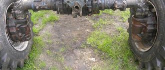
Rear axle design
Rear axle design MTZ-82
The MTZ rear axle transmits torque from the secondary shaft to the rear driven wheels. Its mechanism is mounted in a cast iron body. The front panel of the body houses the gearbox, the rear panel contains the rear shaft gearbox, a transfer element, a support for additional equipment, and a towing mount.
The main gear drive consists of two bevel gears with a spiral tooth. The drive gear is mounted on the secondary shaft. The driven gear is attached to a flange on the differential. The differential connects the driven wheels located on separate axle shafts.
The thoughtful and durable design of the MTZ-82 mini-tractor is a guarantee of long and successful operation. But for this it is necessary to follow the operating rules, regularly carry out maintenance and promptly replace used materials and parts.
Video on the topic: Routine repair of the front axle MTZ-82
Publications on the topic
Features of diagnostics and repair of the KamAZ 5320 gearbox
Advantages and design features of the Belarus MTZ 132N mini-tractor
Features of the MTZ-82 gear shift scheme