Not available:
| № | Part code | Name | Part Information |
| 100-3514071 | Housing assembly | Quantity for MAZ-5337 2) MAZ-53371 3) MAZ-54323 4) MAZ-5516 5) MAZ-5551 6) MAZ-64229 1 Model 100 Group Brakes Subgroup Air brake control valve (brake valve) Serial part number 071 | Not available |
| 100-3514080-01 | Protective shell | Quantity for MAZ-5337 2) MAZ-53371 3) MAZ-54323 4) MAZ-5516 5) MAZ-5551 6) MAZ-64229 1 Model 100 Group Brakes Subgroup Air brake control valve (brake valve) Serial part number 080 | Not available |
| 201460 | Bolt M8-6gх30 | Quantity for MAZ-5337 2) MAZ-53371 3) MAZ-54323 4) MAZ-5516 5) MAZ-5551 6) MAZ-64229 4 Uncoated coating | Not available |
| 305890 | Washer 8 T | Quantity for MAZ-5337 2) MAZ-53371 3) MAZ-54323 4) MAZ-5516 5) MAZ-5551 6) MAZ-64229 4 Uncoated coating | Not available |
| 100-3514013 | Ring | Quantity for MAZ-5337 2) MAZ-53371 3) MAZ-54323 4) MAZ-5516 5) MAZ-5551 6) MAZ-64229 2 Model 100 Group Brakes Subgroup Air brake control valve (brake valve) Serial part number 013 | Not available |
| 100-3514012 | Support plate | Quantity for MAZ-5337 2) MAZ-53371 3) MAZ-54323 4) MAZ-5516 5) MAZ-5551 6) MAZ-64229 1 Model 100 Group Brakes Subgroup Air brake control valve (brake valve) Serial part number 012 | Not available |
| 100-3514070 | Crane lever assembly | Quantity for MAZ-5337 2) MAZ-53371 3) MAZ-54323 4) MAZ-5516 5) MAZ-5551 6) MAZ-64229 1 Model 100 Group Brakes Subgroup Air brake control valve (brake valve) Serial part number 070 | Not available |
| 100-3512099 | Tablet | Quantity for MAZ-5337 2) MAZ-53371 3) MAZ-54323 4) MAZ-5516 5) MAZ-5551 6) MAZ-64229 1 Model 100 Group Brakes Subgroup Pressure regulator Serial part number 099 | Not available |
| 304183 | Rivet | Quantity for MAZ-5337 2) MAZ-53371 3) MAZ-54323 4) MAZ-5516 5) MAZ-5551 6) MAZ-64229 2 Uncoated coating | Not available |
| 100-3514015 | Screw | Quantity for MAZ-5337 2) MAZ-53371 3) MAZ-54323 4) MAZ-5516 5) MAZ-5551 6) MAZ-64229 1 Model 100 Group Brakes Subgroup Air brake control valve (brake valve) Serial part number 015 | Not available |
| 100-3514080 | Protective shell | Quantity for MAZ-5337 2) MAZ-53371 3) MAZ-54323 4) MAZ-5516 5) MAZ-5551 6) MAZ-64229 1 Model 100 Group Brakes Subgroup Air brake control valve (brake valve) Serial part number 080 | Not available |
| 100-3514074 | Lever arm | Quantity for MAZ-5337 2) MAZ-53371 3) MAZ-54323 4) MAZ-5516 5) MAZ-5551 6) MAZ-64229 1 Model 100 Group Brakes Subgroup Air brake control valve (brake valve) Serial part number 074 | Not available |
| 480704 | Screw | Quantity for MAZ-5337 2) MAZ-53371 3) MAZ-54323 4) MAZ-5516 5) MAZ-5551 6) MAZ-64229 2 Uncoated coating | Not available |
| 484107 | Pin | Quantity for MAZ-5337 2) MAZ-53371 3) MAZ-54323 4) MAZ-5516 5) MAZ-5551 6) MAZ-64229 1 Uncoated coating | Not available |
| 100-3514076 | Axis | Quantity for MAZ-5337 2) MAZ-53371 3) MAZ-54323 4) MAZ-5516 5) MAZ-5551 6) MAZ-64229 1 Model 100 Group Brakes Subgroup Air brake control valve (brake valve) Serial part number 076 | Not available |
| 100-3514075 | Video clip | Quantity for MAZ-5337 2) MAZ-53371 3) MAZ-54323 4) MAZ-5516 5) MAZ-5551 6) MAZ-64229 1 Model 100 Group Brakes Subgroup Air brake control valve (brake valve) Serial part number 075 | Not available |
| 100-3514073 | Sleeve | Quantity for MAZ-5337 2) MAZ-53371 3) MAZ-54323 4) MAZ-5516 5) MAZ-5551 6) MAZ-64229 2 Model 100 Group Brakes Subgroup Air brake control valve (brake valve) Serial part number 073 | Not available |
| 100-3514078 | Cork | Quantity for MAZ-5337 2) MAZ-53371 3) MAZ-54323 4) MAZ-5516 5) MAZ-5551 6) MAZ-64229 1 Model 100 Group Brakes Subgroup Air brake control valve (brake valve) Serial part number 078 | Not available |
| 309792 | Ring | Quantity for MAZ-5337 2) MAZ-53371 3) MAZ-54323 4) MAZ-5516 5) MAZ-5551 6) MAZ-64229 1 Uncoated coating | Not available |
| 100-3514072 | Frame | Quantity for MAZ-5337 2) MAZ-53371 3) MAZ-54323 4) MAZ-5516 5) MAZ-5551 6) MAZ-64229 1 Model 100 Group Brakes Subgroup Air brake control valve (brake valve) Serial part number 072 | Not available |
| 100-3514077 | Sleeve | Quantity for MAZ-5337 2) MAZ-53371 3) MAZ-54323 4) MAZ-5516 5) MAZ-5551 6) MAZ-64229 1 Model 100 Group Brakes Subgroup Air brake control valve (brake valve) Serial part number 077 | Not available |
| 100-3514079 | Pusher | Quantity for MAZ-5337 2) MAZ-53371 3) MAZ-54323 4) MAZ-5516 5) MAZ-5551 6) MAZ-64229 1 Model 100 Group Brakes Subgroup Air brake control valve (brake valve) Serial part number 079 | Not available |
| 250508 | Nut M6-6N | Quantity for MAZ-5337 2) MAZ-53371 3) MAZ-54323 4) MAZ-5516 5) MAZ-5551 6) MAZ-64229 1 Uncoated coating | Not available |
| 305887 | Washer | Quantity for MAZ-5337 2) MAZ-53371 3) MAZ-54323 4) MAZ-5516 5) MAZ-5551 6) MAZ-64229 1 Uncoated coating | Not available |
| 305893 | Washer 6 | Quantity for MAZ-5337 2) MAZ-53371 3) MAZ-54323 4) MAZ-5516 5) MAZ-5551 6) MAZ-64229 1 Uncoated coating | Not available |
| 302200 | Screw | Quantity for MAZ-5337 2) MAZ-53371 3) MAZ-54323 4) MAZ-5516 5) MAZ-5551 6) MAZ-64229 1 Uncoated coating | Not available |
| 100-3514056 | Spring plate | Quantity for MAZ-5337 2) MAZ-53371 3) MAZ-54323 4) MAZ-5516 5) MAZ-5551 6) MAZ-64229 1 Model 100 Group Brakes Subgroup Air brake control valve (brake valve) Serial part number 056 | Not available |
| 100-3514055 | Balancing element | Quantity for MAZ-5337 2) MAZ-53371 3) MAZ-54323 4) MAZ-5516 5) MAZ-5551 6) MAZ-64229 1 Model 100 Group Brakes Subgroup Air brake control valve (brake valve) Serial part number 055 | Not available |
| 100-3514035 | Ring | Quantity for MAZ-5337 2) MAZ-53371 3) MAZ-54323 4) MAZ-5516 5) MAZ-5551 6) MAZ-64229 2 Model 100 Group Brakes Subgroup Air brake control valve (brake valve) Serial part number 035 | Not available |
| 100-3514052 | Upper piston | Quantity for MAZ-5337 2) MAZ-53371 3) MAZ-54323 4) MAZ-5516 5) MAZ-5551 6) MAZ-64229 1 Model 100 Group Brakes Subgroup Air brake control valve (brake valve) Serial part number 052 | Not available |
| 100-3514050 | Spring | Quantity for MAZ-5337 2) MAZ-53371 3) MAZ-54323 4) MAZ-5516 5) MAZ-5551 6) MAZ-64229 1 Model 100 Group Brakes Subgroup Air brake control valve (brake valve) Serial part number 050 | Not available |
| 100-3514033 | Ring | Quantity for MAZ-5337 2) MAZ-53371 3) MAZ-54323 4) MAZ-5516 5) MAZ-5551 6) MAZ-64229 2 Model 100 Group Brakes Subgroup Air brake control valve (brake valve) Serial part number 033 | Not available |
| 100-3514047 | Washer | Quantity for MAZ-5337 2) MAZ-53371 3) MAZ-54323 4) MAZ-5516 5) MAZ-5551 6) MAZ-64229 1 Model 100 Group Brakes Subgroup Air brake control valve (brake valve) Serial part number 047 | Not available |
| 100-3514046 | Valve | Quantity for MAZ-5337 2) MAZ-53371 3) MAZ-54323 4) MAZ-5516 5) MAZ-5551 6) MAZ-64229 1 Model 100 Group Brakes Subgroup Air brake control valve (brake valve) Serial part number 046 | Not available |
| 100-3514045 | Frame | Quantity for MAZ-5337 2) MAZ-53371 3) MAZ-54323 4) MAZ-5516 5) MAZ-5551 6) MAZ-64229 1 Model 100 Group Brakes Subgroup Air brake control valve (brake valve) Serial part number 045 | Not available |
| 100-3514048 | Rivet | Quantity for MAZ-5337 2) MAZ-53371 3) MAZ-54323 4) MAZ-5516 5) MAZ-5551 6) MAZ-64229 1 Model 100 Group Brakes Subgroup Air brake control valve (brake valve) Serial part number 048 | Not available |
| 100-3514032-01 | Large piston | Quantity for MAZ-5337 2) MAZ-53371 3) MAZ-54323 4) MAZ-5516 5) MAZ-5551 6) MAZ-64229 1 Model 100 Group Brakes Subgroup Air brake control valve (brake valve) Serial part number 032 | Not available |
| 100-3514028 | Ring | Quantity for MAZ-5337 2) MAZ-53371 3) MAZ-54323 4) MAZ-5516 5) MAZ-5551 6) MAZ-64229 1 Model 100 Group Brakes Subgroup Air brake control valve (brake valve) Serial part number 028 | Not available |
| 489306 | Resistant ring | Quantity for MAZ-5337 2) MAZ-53371 3) MAZ-54323 4) MAZ-5516 5) MAZ-5551 6) MAZ-64229 1 Uncoated coating | Not available |
| 100-3514030 | Clip | Quantity for MAZ-5337 2) MAZ-53371 3) MAZ-54323 4) MAZ-5516 5) MAZ-5551 6) MAZ-64229 1 Model 100 Group Brakes Subgroup Air brake control valve (brake valve) Serial part number 030 | Not available |
| 201458 | Bolt M8-6ghx25 | Quantity for MAZ-5337 2) MAZ-53371 3) MAZ-54323 4) MAZ-5516 5) MAZ-5551 6) MAZ-64229 4 Uncoated coating | Not available |
| 305890 | Washer 8 T | Quantity for MAZ-5337 2) MAZ-53371 3) MAZ-54323 4) MAZ-5516 5) MAZ-5551 6) MAZ-64229 4 Uncoated coating | Not available |
| 100-3536029 | Ring | Quantity for MAZ-5337 2) MAZ-53371 3) MAZ-54323 4) MAZ-5516 5) MAZ-5551 6) MAZ-64229 2 Model 100 Group Brakes Subgroup Equipment for dehydration of compressed air Serial part number 029 | Not available |
| 100-3513028 | Ring | Quantity for MAZ-5337 2) MAZ-53371 3) MAZ-54323 4) MAZ-5516 5) MAZ-5551 6) MAZ-64229 2 Model 100 Group Brakes Subgroup Air cylinders for pneumatic brakes Serial part number 028 | Not available |
| 100-3514027 | Support ring | Quantity for MAZ-5337 2) MAZ-53371 3) MAZ-54323 4) MAZ-5516 5) MAZ-5551 6) MAZ-64229 2 Model 100 Group Brakes Subgroup Air brake control valve (brake valve) Serial part number 027 | Not available |
| 100-3514026 | Spring | Quantity for MAZ-5337 2) MAZ-53371 3) MAZ-54323 4) MAZ-5516 5) MAZ-5551 6) MAZ-64229 2 Model 100 Group Brakes Subgroup Air brake control valve (brake valve) Serial part number 026 | Not available |
| 100-3514024 | Cap | Quantity for MAZ-5337 2) MAZ-53371 3) MAZ-54323 4) MAZ-5516 5) MAZ-5551 6) MAZ-64229 2 Model 100 Group Brakes Subgroup Air brake control valve (brake valve) Serial part number 024 | Not available |
| 100-3514022 | Valve body | Quantity for MAZ-5337 2) MAZ-53371 3) MAZ-54323 4) MAZ-5516 5) MAZ-5551 6) MAZ-64229 1 Model 100 Group Brakes Subgroup Air brake control valve (brake valve) Serial part number 022 | Not available |
| 100-3514023 | Clamp | Quantity for MAZ-5337 2) MAZ-53371 3) MAZ-54323 4) MAZ-5516 5) MAZ-5551 6) MAZ-64229 2 Model 100 Group Brakes Subgroup Air brake control valve (brake valve) Serial part number 023 | Not available |
| 100-3514020 | Bolt M8x1.25-6gx12 | Quantity for MAZ-5337 2) MAZ-53371 3) MAZ-54323 4) MAZ-5516 5) MAZ-5551 6) MAZ-64229 1 Model 100 Group Brakes Subgroup Air brake control valve (brake valve) Serial part number 020 | Not available |
| 100-3514034 | Cap | Quantity for MAZ-5337 2) MAZ-53371 3) MAZ-54323 4) MAZ-5516 5) MAZ-5551 6) MAZ-64229 1 Model 100 Group Brakes Subgroup Air brake control valve (brake valve) Serial part number 034 | Not available |
| 100-3514036 | Shaft | Quantity for MAZ-5337 2) MAZ-53371 3) MAZ-54323 4) MAZ-5516 5) MAZ-5551 6) MAZ-64229 1 Model 100 Group Brakes Subgroup Air brake control valve (brake valve) Serial part number 036 | Not available |
| 100-3514049 | Lower housing | Quantity for MAZ-5337 2) MAZ-53371 3) MAZ-54323 4) MAZ-5516 5) MAZ-5551 6) MAZ-64229 1 Model 100 Group Brakes Subgroup Air brake control valve (brake valve) Serial part number 049 | Not available |
| 100-3514040 | Sleeve | Quantity for MAZ-5337 2) MAZ-53371 3) MAZ-54323 4) MAZ-5516 5) MAZ-5551 6) MAZ-64229 1 Model 100 Group Brakes Subgroup Air brake control valve (brake valve) Serial part number 040 | Not available |
| 100-3514042 | Ring | Quantity for MAZ-5337 2) MAZ-53371 3) MAZ-54323 4) MAZ-5516 5) MAZ-5551 6) MAZ-64229 1 Model 100 Group Brakes Subgroup Air brake control valve (brake valve) Serial part number 042 | Not available |
| 100-3514044 | Exhaust window assembly | Quantity for MAZ-5337 2) MAZ-53371 3) MAZ-54323 4) MAZ-5516 5) MAZ-5551 6) MAZ-64229 1 Model 100 Group Brakes Subgroup Air brake control valve (brake valve) Serial part number 044 | Not available |
| 489310 | Resistant ring | Quantity for MAZ-5337 2) MAZ-53371 3) MAZ-54323 4) MAZ-5516 5) MAZ-5551 6) MAZ-64229 1 Uncoated coating | Not available |
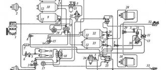
Brake valve of MAZ car
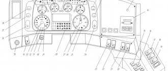
Removal and disassembly of the brake valve (Fig. 1) is carried out in the following order:
— remove the brake pedal release spring and disconnect the brake pedal rod from the lever;
— disconnect all pipelines from the brake valve;
— disconnect the bolts securing the brake valve bracket and remove the brake valve;
— unscrew the bolts and remove the support plate 32 together with the lever body 7 and lever 1, remove the pusher 6;
— remove the upper piston 30 with the balancing element assembly;
— remove spring 12;
— unscrew the bolts and disconnect the upper housing 33 and the lower housing 25;
— remove the large piston 28 and the small piston 15 as an assembly, then remove the small piston from the large one, remove the spring 26;
— remove the retaining ring 22 and take out the seal, support ring, spring 24 and body with valve 17 of the lower section;
— remove the retaining ring and take out the outlet window, support ring and upper section valve assembly;
— remove lever 1 of the brake valve, for which remove the axle;
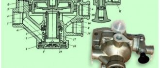
— when installing the upper piston, measure the distance “C” (Fig. 2), the protrusion of the shank of the small piston above the valve. Using the adjusting screw on the upper piston, set the distance d = C + 0.8 mm
— install the upper piston 30 (see Fig. 1);
— assemble the crane with the base plate and lever;
- put on a protective cover.
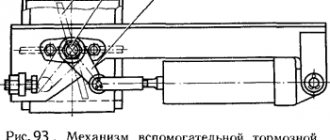
After assembly, the operation of the brake valve must be checked on a bench at an air pressure in the system of 687 kPa. The test circuit is shown in Fig. 3.
The verification procedure is as follows:
— connect the pipelines to terminals 11* and 12*. Press the lever several times until it stops (stroke S, min = 31.2 mm).
Air flow through the terminals should be good.
With the lever released, check terminals 21*, 22* and 3* for leaks using soap emulsion;
connect pins 21, 22 to the cylinders. When you smoothly press the lever, the first circuit should operate after the lever stroke is (5.7 + 1.5) mm, which corresponds to the pusher stroke (2.3 + 0.6) mm.
The initial pressure surge in the primary circuit should not exceed 20 kPa;
when the pressure in the primary circuit reaches 50 kPa, the pressure in the second circuit must be at least 245 kPa.
The advance of pressure in the primary circuit relative to the pressure in the secondary circuit can be maintained over the entire pressure range, but not exceed 25 kPa.
The initial pressure surge in the secondary circuit should not exceed 20 kPa;
— the lever stroke up to a pressure of 294 kPa in the primary circuit should be (17.2d: 1.7) mm, which corresponds to the pusher stroke (6.9 ± 0.7) mm;
— the lever stroke up to a pressure of 687 kPa in the first and second circuits should be (24±2.4) mm, which corresponds to the pusher stroke (9.6±1) mm;
— the total stroke of the lever to the stop should be (34.6 ± 3.5) mm, which corresponds to the stroke of the pusher (13.9 + 1.4) mm;
— when you smoothly press the lever, after the initial jump, the pressure in each circuit should gradually increase, and when released, it should gradually decrease. The pressure reduction step should not exceed 294 kPa;
— if the first or second circuit fails, the remaining circuit must remain fully operational;
— check the valve for leaks in the inlet position.
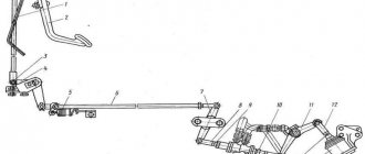
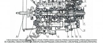
The valve is installed on the vehicle in the reverse order of removal. It is possible to install a brake valve (Fig. 4).
Brake modification valve No. 2
Removal and disassembly of the brake valve (Fig. 4) is carried out in the following order:
— raise the car cabin;
— disconnect all pipelines from the brake valve;
— unscrew bolts 27 and remove the brake valve, preventing pusher 1 from falling out;
— remove the upper piston 25 with the elastic element 26 assembled;
— remove spring 7;
— unscrew the bolts and disconnect the upper housing 28 and the lower housing 20;
- remove spring 21, large piston 23 assembled with small piston 10, and then remove the small piston from the large one;
— remove the locking ring 17 and take out the atmospheric outlet housing 18 with sealing rings, support ring 14, spring 19 and lower section valve 12;
— remove the retaining ring and take out the seal, support ring 9, spring 8 and upper section valve 24.
Reassemble the tap in the reverse order of disassembly. Before installing the upper piston, measure the distance “C” (Fig. 2) - the protrusion of the small piston shank above the valve.
Using the adjusting screw on the upper piston, set the distance d = c + 0.8 mm and lock the adjusting screw.
After assembly, it is necessary to check the operation of the brake valve on a stand at an air pressure in the system of 0.7 MPa (7.0 kgf/cm2).
The test diagram is shown in Fig. 5.
The verification procedure is as follows:
— connect the pipelines, plug unused terminals. Press the pusher three times until it stops.
With the pusher released, check terminals 21, 22 and 23 for leaks using soap emulsion;
—- connect terminals 21 and 22 to the cylinders and smoothly press the pusher.
The first circuit (upper) should operate after a pusher stroke of 1.9-3.0 mm. The initial pressure surge should not exceed 0.02 MPa (0.2 kgf/cm2);
— when the pressure in outlet 21 reaches 0.05 MPa (0.5 kgf/cm2), the pressure in outlet 22 must be at least 0.025 MPa (0.25 kgf/cm2).
The advance of pressure in outlet 21 relative to the pressure in outlet 22 can be maintained over the entire pressure range, but not exceed 0.025 MPa (0.25 kgf/cm2).
The initial pressure surge in terminal 22 should not exceed 0.02 MPa (0.2 kgf/cm2).
when the pressure in terminal 21 reaches 0.3 MPa (3.0 kgf/cm2), the pusher stroke should be (5.8-8.0) mm;
when the pressure in terminal 21 reaches 0.75 MPa (7.5 kgf/cm2), the pusher stroke should be (8.4-10.8) mm;
the total stroke of the pusher to the stop should be (12.5-15.7) mm;
— when you smoothly press the pusher, after the initial jump, the pressure in each circuit should gradually increase, and when released, it should gradually decrease;
— check the tightness of the tap with the pusher pressed all the way;
— check the tightness with the pusher of the first circuit pressed all the way and there is no pressure in the second circuit, and then the tightness of the second circuit when there is no pressure in the first.
Install the tap in the reverse order.
Repair
Any equipment breaks down for some reason. It is important to know the structure of the device and understand what leads to a decrease in functionality.
For example, a MAZ 5440 floor level tap can freeze (like any other model). The solution to the problem is quite simple: remove the condensate and check the eccentric. For a complete repair, some experienced drivers recommend a complete replacement of both sensors and calibration.
Much less often, a control panel or valve block occurs. For example, you need to diagnose the MAZ 6430 floor level valve. If the air suspension indicators do not light up when the ignition is turned on, then first check the fuses.