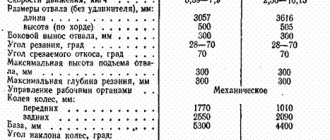
Specifications
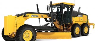
The GS 14.02 motor grader is a modern 140 class machine, the design of which uses domestic and imported components. Large components and assemblies are created in accordance with user requirements for the technical performance of construction machines. The grader is equipped with various power units and offers owners advanced capabilities.
- Class - 140;
- Operating weight, kg - 13,500;
- Engines D442 / D260 / YaMZ-236 / Cummins 6VT5.9-S135 / Cummins 6VTA-S165;
- Transmission - mechanical;
- Travel speed GS-14.02, km/h: 4.1-34.2;
- Number of motor grader gears: forward - 6; back – 2;
- The wheel formula of the motor grader is 1x2x3;
- Overall dimensions GS-14.02, mm 8820x2500x3475;
- Tires: 14.00-20.00;
- Grader blade: Overall dimensions, mm - 3740x620x250;
- Removal, mm - 800;
- Slope cleaning angle, degrees - 90.
Engine
The manufacturer offers customers a choice of five trim levels. Initially, the car was equipped with a domestic D-442 engine. This is a turbocharged diesel with a rated power of 100 hp. Later, models with power units D-260 and YaMZ-236 with rated power of 100 and 110 hp became available. respectively.
The most modern machines are equipped with imported engines from the American brand Cummins. The Cummins 6ВТ5.9-С135 model produces a maximum power of 100 hp. The Cummins 6VTA-C165 model operates at a maximum power of 120 hp. American engines are reliable and do not require serious repairs over a long period of time. On the other hand, Russian power units are cheaper to maintain, and spare parts for the GS 14.02 motor grader motors are available in any region.
Fuel consumption
This model of the device is equipped with a large fuel tank of 490 liters. Various motor grader configurations use their own engines, so fuel consumption depends on their power. Most often, engines with a consumption of 220 -230 g/kWh are used for these purposes.
Transmission
Modern GS 14.02 graders are equipped with automatic gearboxes of the German ZF brand. As standard with the domestic power unit, the car comes with a manual transmission. GS 14.02 can move with six forward and two reverse speeds. In this case, the speed range is 4.1-34.2 km/h.
The manufacturer used a 1x2x3 wheel arrangement in the grader's chassis. Base models are equipped with 14.00-20 tires. The gearbox is complemented by a NAF tandem bogie and a No-Spin differential. The service braking system is represented by disc brakes controlled by a pedal. The device uses a dual-circuit brake system that provides equal force on all wheels of the motor grader. To increase reliability, the brake mechanism is equipped with a backup power source.
Hydraulic system
The GS 14.02 hydraulic system uses a constant volume pump with an additional system for unloading the working unit when the control handle is in the neutral position. The functioning of the system is ensured by six manual hydraulic valves, with the help of which the working bodies are controlled. Four electric hydraulic valves are used to perform related operations.
Working equipment and blade characteristics
The GS 14.02 motor grader is equipped with a full-rotating grader blade with the following characteristics:
- length - 3740 mm;
- height - 620 mm;
- lowering below the supporting surface - 250 mm;
- offset - 800 mm;
- slope cleaning angle is 90 degrees.
The manufacturer supplies the following as replacement working equipment:
- side grader blade;
- rotary bulldozer blade;
- rear ripper.
Spare parts for motor grader GS-14.02
Spare parts for motor grader GS-14.02
The GS-14.02 motor grader is designed to perform large volumes of excavation and profiling work during the construction and maintenance of roads. GS-14.02 is equipped with a powerful 110 kW engine and mechanical transmission.
240301100029-02 Bushing 240301100029-01 Bushing 46121329630 Bearing 212 99904103 Ring B110 240301100029 Bushing 240301100028 Cover 99504041 Washer 56.0 2.06 99405069 Nut M56x2 46121329632 Bearing 312 240301100025 Cover 240301100006 Gasket 97060224 Cuff 12-75x100-1 240301100023 Ring 240301100054 Ga yka 240301100055 Washer 240301100060 Ring 240301100050 Washer 240301100022 Cover 240301100013 Gasket 240301100029-03 Bushing 46121329633 Bearing 314 999904127 Ring B150 240301100012-03 Bushing 461213299631 Bearing 2 15 99904093 Ring B130 240301100012-02 Bushing
240301100018 Clutch 8771030 Magnetic plug 240301100063 Housing 240301100065 Gasket 240301100015 Gear Z=30 240301110000 Speedometer drive 240301100012-01 Bushing 24030 1100012 Bushing 240301100014 Washer 240301100010 Gear Z=49 7001605022 Pin 240301100072 Speedometer gear Z=4, m=1.25 240301100009 Gear Z=41 240301100008 She stubble Z =24 240301300003 Cover 92312 Bearing 92312 99904009 Ring B60 240301100004 Gear Z=30 240301100003 Gear Z=19 46121329634 Bearing 410 99904101 Ring B50 24 0.30.13.01.200 Lever 240.30.13.03.000 Lever 240301302000 Rod 240301106000 Roller 240301100041 Stopper 240301103000 Locking roller 240301100058 Locking device 0856 0128 Gasket 08771036 Plug 240301100059 Roller Wire 2-0-C Wire 2-0-C 240301100053 Cover 97040047 Ring 026-032-36-2-2 240301100052 Fork 240301100049 Stopper 2 40301100021 Fork 240301100040 Fork 225.73.06.01.012-80 Spring for motor grader 225.73. 06.01.013-80 Spring for motor grader 225.73.06.01.015-80 Spring for motor grader 225.73.06.01.017-80 Spring for motor grader 200.03.06.03.000-01 Hydraulic cylinder for motor grader GS-14.02 225.73.06. 01.100-80 Block for motor grader 225.73.06.01.100-81 Shoe for motor grader 0.820.2056 Nut for motor grader GS-14.02 225.73.04.00.000 Brake drum with hub for motor grader 225.03.00.00.002 Conical bushing for motor grader GS-14 .02 A-120.62.00.000 Axle gearbox rear for motor grader 248.03.02.00.000 Balancer assembly for motor grader 248.03.02.02.000 Balancer housing for motor grader 248.03.02.00.001 Gear for motor grader GS-14.02 240.03.02.00.002 Gear for motor grader GS-14.0 2 225.73.02.00.010- 01 Shaft for motor grader 225.63.02.02.000 Rear brake hub for motor grader 240301300006 Fork 240301100046 Spring 240301100045 Washer 240301300002 Roller 240301300002-01 Roller 2403 01101004 Spring 240301101003 Spring plate 06210020 Pin 240301101002 Cover 240301101001 Column 14.00-20 Model OI-25 NS14 Tire (with chamber 14 -20, valve RK-5A-145 OST 37.001.215 and rim tape 300-508) original factory 380-310.10.12 Wheel 8.5-20 disc GOST 10409 253.01.12.00.000 -10 Front frame equipment for motor grader 225.81. 02.00.000 Locking cylinder for motor grader 225.81.01.04.000 Bracket for motor grader GS-14.02 250.01.01.00.000-10 Sub-motor frame equipment 751.01.00.00.002 Cover for motor grader GS-14.02 GE-80SX By bearing for motor grader GS-14.02 751.01. 03.00.000 Mounting axle for motor grader GS-14.02 281.05.02.00.000 Installation of hydraulic distributors for motor grader RM12-116 Hydraulic distributors RM-12-116 240301110001 Housing 240301110009 Speedometer roller Z=15,m=1.25 2403 01110003 Cover 97060128 Cuff 1.2-10x25-1 D100 -14.20 TU BY 790244540.001-2010 Metering pump D-100 250.05.01.07.000 Hydraulic distributor for motor grader 250.05.01.03.000 Pressure filter for motor grader AMZ-SR-AV Hydraulic lock for motor grader GS-14.02 KPR-1 0/3 TM-2V Valve charging for a motor grader 250.47.02.00.000 Installation of a pedal for a motor grader 250.11.02.00.000 Charging valve for a motor grader 274.11.02.00.000 Disconnect valve for a motor grader 200.05.08.01.000-01 Hydraulic booster for a motor grader 225.67 .00.00.001 Ball pin for motor grader 225.67.09.00.000-01 Gearbox without hydraulic motor for motor grader 225.67.06.00.000-02 Hydraulic joint for motor grader 225.07.00.00.007 Carrier for motor grader GS-14.02 225.07.02.00.001 Narrow crown for motor grader GS -14.02 248.07.01.01. 000-02 Left bracket (without liner) 248.07.01.01.000-03 Right bracket (without liner) 248.07.01.00.001 Insert for motor grader GS-14.02 225.07.13.00.001 Insert for motor grader GS-14.02 225.07. 14.00.000 Knife - blade for motor grader GS-14.02 225.67.11.01.000-01 Turning circle for motor grader 274.07.01.00.000 Traction frame for motor grader 225.07.00.00.019 Cover for motor grader GS-14.02 225.07.14.01.000 Blade for motor grader GS-14.02 225.07 .04.00.004 Knife for motor grader GS-14.02 225.07.04.00.005 Knife for motor grader GS-14.02 225.07.04.00.001-02 Bolt for motor grader 240301110004 Washer 240301110005 Gasket 201A Bearing 201A 240301110006 Cover 240301301100 Rocker assembly 240301301001 Housing 240301301004 Roller 240301301006 Lever 240301301000 Switching mechanism assembly 4112109700 Hydraulic distributor RM 12-29 253450101001-01 Fitting 253450101001 Fitting 08711188 Fitting 08771187-01 Fitting 08771188-01 Fitting 0 8711187 Fitting 253050000020 Ring 99420001 Union nut 3-12 248040600000 Installation of levers 248040600001 Seal 225040300007 Spring 250.02.01.00.000 Installation pump NSh-10 UZ 250.02.05.01.000 Brake for motor grader GS-14.02 250.02.05.01.500 Brake block for motor grader 250.02.05.01.002 Spacer for motor grader 250.02.05.01.200 Lever comes complete with motor for motor grader ydera 277.17.00.00 .000-02 Installation of cardan shafts and parking brake for a motor grader 240.30.03.00.000-00 Gearbox with mechanic's brackets Pskov 240.30.13.01.000-01 Gearbox shift mechanism for a motor grader 240.30.13.02.000 Traction for a motor grader GS-14. 02 274.08 .03.00.000 Fork for motor grader GS-14.02 240.30.11.05.000 Fork for motor grader GS-14.02 240.30.13.03.000 Lever for motor grader GS-14.02 240.30.11.00.072 Gear for motor grader GS-14.0 2 240.30.11.10.000 Speedometer drive for motor grader 248.03.06.00.000-01 Rear wheel brake for motor grader 225.73.06.01.004-80 Spring for motor grader 99502026 Washer 10 65G 99109053 Bolt M10x50 225040307001 Friction ring 995 03124 Washer 12 99401376 Nut M12 225040307002 Spring 225040307700 Clamp 271040203000 Gas pedal 99109051 Bolt M10 ×25 225.07.04.00.001-01 Bolt for motor grader 225.07.04.00.001 Bolt for motor grader 225.07.04.00.004-01 Knife for motor grader 225.67.09.00.000-01 Gearbox without hydraulic motor 225.67.09.00. 001 Housing for motor grader 225.67. 02.00.001 Shaft for motor grader 225.67.09.02.000 Adapter for motor grader 225.07.00.00.029 Bushing for motor grader 225.07.00.00.027 Bushing for motor grader 225.07.05.00.013 Cover for motor grader 225.6 7.09.03.000 Cover for motor grader 225.67.09.00. 005 Worm wheel for motor grader 225.67.09.01.000 Shaft for motor grader GS-14.02 225.67.09.00.003 Gasket for motor grader 225.67.09.00.002 Cover for motor grader 225.67.09.00.007 Gear Z=8 22 5.07.05.00.023 Washer for motor grader 225.07 .05.00.022 Washer for motor grader 97060224 Cuff 1.2-75x100-1 GOST 8752-79 97040069 Ring 140-150-58-2-2 GOST 9833-73 225.05.10.06.000 Fork for motor grader GTSO2-80x5 0x160B Hydraulic cylinder for motor grader GTSO2- 80x50x280. 000B Hydraulic cylinder for motor grader 260.06.00.00.001 Front hub for motor grader 225.66.03.00.003 Bushing for motor grader 260.06.00.00.007 Cover for motor grader 260.06.01.00.000 Left lever for motor grader 22 5.66.03.00.000 Right lever for motor grader 225.66.00.00 .003 Bipod for motor grader 260.06.00.00.006 Wheel pin for motor grader 260.06.00.00.003 Cover for motor grader 200.36.00.00.020 Axle for motor grader 225.06.00.00.006 Axle pin for motor grader 260.06.0 0.00.011 Traction fork for motor grader 260.06. 00.00.002 Axle for motor grader 225.66.02.00.000 Front axle traction for motor grader 225.66.00.00.014 Axle for motor grader 225.66.00.00.015 Crosspiece for motor grader 225.66.00.00.004 Bushing (bronze) for motor grader dera 225.66.00.00.015-01 Crosspiece for motor grader 260.06.00.00.004 Bushing for motor grader 225.66.00.00.010 Fork for motor grader 225.66.00.00.011 Fork for motor grader 225.66.00.00.012 Rod for motor grader 225.21.12.00.000 Traction for motor grader 253.21.02.00.000 Bulldozer blade for motor grader 253.21.01.00.000 Support for motor grader 225.07.04.00.005 Knife (1820 mm) for motor grader 225.21.00.00.008 Knife (604 mm) for motor grader 225.39.03.00.000 Ripper tooth for motor grader 225.1 9.06.00.007 Tip for motor grader 271.19.01.00.000 Front frame for motor grader 150.01.01.00.000 Hydraulic distributor for motor grader HD3-ES-3C-K-024C Hydraulic distributor (Italy) MRS-02W Hydraulic lock (Italy) 250.25.00.00.000 Facing for motor grader 250.25.15.00. 000 Tank block for motor grader 271.25.15.06.000 Drain filter for motor grader 250.04.00.00.000-01 Cabin assembly for motor grader 250.41.00.00.000 Cabin heating system for motor grader 250.09.00.00.000-01 Electrical equipment for cabins (+ wiring) 250.04 .01.02.000 Lock for motor grader 250.04.01.02.000-01 Lock for motor grader 250.04.00.00.002 Traction for motor grader F2001/80Hx Driver's seat F2001/80Нх 4301-3402015 Steering wheel 4301-3402 015 TU6-19-296 274.04.00.00. 001 Windshield (950x860x1636 mm) 250.04.00.00.001 Door glass for motor grader 274.04.00.00.003 Side glass for motor grader 225.44.00.00.010-01 Rear glass for motor grader 250.02.06.00.0 00 Cooling system 4 150U.13.01.010- 4-02 Water radiator TU 23461771059-89E 150U.08.000-1 Oil radiator for a motor grader 250.02.03.00.000 Installation of an air cleaner for a motor grader 250.02.04.00.000 Installation of a muffler assembly for a motor grader 250.02.09.00.0 00 Installation of pump NSh-32 DKM- 3 (with pump NSh-32) 250.02.09.00.000 Installation of pump NSh-32 DKM-3 (without pump NSh-32) 250.02.08.00.000 Power system for motor grader 200.16.00.01.000 Shock absorber for motor grader GS-14.02 630300- 1001020 Engine cushion for motor grader 630300-1001029 Shock absorber for motor grader ГЦО5- 80х50х400 Hydraulic cylinder for motor grader ГЦО5- 80х50х710 Hydraulic cylinder for motor grader ГЦО5- 80х50х1000-01 Hydraulic cylinder for motor grader ГЦО2-100х50х250А Hydraulic cylinder for motor grader dera 225.07.06.00.000 Blade extension for motor grader 225.66.10.00.000 Steering for motor grader 225.81.02.00.000 Clamp cylinder for motor grader 99401374 Nut M10 248080000016 Fork 248080000006 Rod 248081200000 Roller 225080000002 Bracket 99503103 Washer 1 0 99601161 Cotter pin 2×20 225080000008 Rod 225040300009 Pin 4751347001-01 Bushing
You can always buy spare parts for the GS-14.02 motor grader from our company. We also sell spare parts for motor graders A-120, DZ-98, DZ-122, DZ-143, DZ-180, GS-10.01, GS-14.02, GS-18.05, GS-25.09, etc.
supplies spare parts for the GS-14.02 motor grader to all regions of the Russian Federation, as well as to the CIS countries and Kazakhstan.
Device
A machine of this class is used for road surface planning and profiling. Additionally, it is used to create embankments from gravel, various types of soil and crushed stone by leveling and moving them. In winter, it is allowed to use the GS-14.02 motor grader to clear road transport routes from precipitation and formed ice. This is possible due to the wide range of operating temperatures and adaptation to work in tropical and temperate latitudes.
A wide grip on the grader blade is achieved through the use of an articulated frame and rotary grader and bulldozer blades. This design also allows the machine to be used for profiling in the opposite direction of movement due to the reverse gear. The blade is located directly between the front and rear axles and is fully rotatable.
The design feature of the GS-14.02 motor grader is that it is equipped with removable equipment. Therefore, its bulldozer blade can be replaced with a ripper-pick, and it, in turn, can be replaced with a ripper-scarifier. The power of the equipment directly depends on the engine used, but due to the fact that there are several design options, each modification should be considered separately, based on the technical characteristics.
The GS-14.02 motor grader is adapted for work in high mountain areas. This is largely possible thanks to the transmission used. It's made in Germany here. The brake system is dual-circuit hydraulic with a backup power source. It is complemented by a parking brake with gear lock. The hydraulics are supplied with a constant volume pump. It includes 6 hydraulic boosters for the main equipment and four electrical modules for additional equipment, as well as hydraulic locks for the circuits.
The operator's work is facilitated by the automatic blade control system. For this purpose, the design provides a number of sensors and balancers, also containing sensors.
dimensions
- length - 8820 mm;
- width - 2500 mm;
- cabin roof height - 3475 mm;
- operating weight - 13,500 kg.
Controls
The steering operates on the front pair of swivel wheels through a drive consisting of two hydraulic cylinders. There is no mechanical connection between the wheels and the steering column.
The use of the drive, the tilt of the steering wheels and the bending of the frame provides the unit with a turning radius of 7.8 m.
Shoe brakes with hydraulic drive are installed on the wheels of the rear axle. The disc-type parking brake acts on the drive gear shaft of the central gearbox. Cab mounting dampers, heating and ventilation devices, and spring seat suspension create comfortable conditions for the operator.
The cabin equipment is well thought out, and the interior ergonomics are modern. Glazing with a minimum of closed areas, headlights and mirrors provide visibility of the working area and visual control of the motor grader components.
The cabin, reinforced with steel inserts, protects the operator in emergency situations. The turntable for mounting the grader blade is secured in three places by clamping devices. It is controlled by a pair of hydraulic cylinders with valves configured to relieve shock loads.
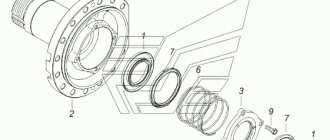
Grader GS 14 02 front hub diagram
Motor grader GS-14.02. Front axle
The front axle (Figure 13) is attached to the motor grader frame using axle 36. On the axle, the front axle can freely rotate in a plane perpendicular to the axis of the machine, which ensures constant contact of all wheels with the ground and ensures the leveling ability of the motor grader. The swing of the front axle is limited by stops on the frame bracket.
At the ends of the beam, brackets 3 are installed in the forks with axles on which the wheel hubs are mounted. The wheel axles are equipped with levers connected by rod 44.
Fenders (mud flaps) are installed on the pins that secure the wheel axles, which turn and tilt along with the wheels.
The rotation of the wheels is carried out by hydraulic cylinders 6, the sleeves of which are fixed to the axle 36 by forks, and the rods are connected by crosses 34 with levers.
The wheels are tilted using a hydraulic cylinder 5, one end of which is fixed by a pin to the beam 43, and the other to the left bracket 3. The brackets are connected to each other by a rod 4. When the rod moves, the left bracket rotates around the axis and turns the right bracket through the rod, and the brackets through The hub axles tilt the wheels.
Figure 13 Front axle
1.9-wheel, 2.10-axle shaft, 3.8-wheel tilt bracket, 4-rod, 5-hydraulic cylinder,
6-hydraulic wheel steering cylinder, 7-brace, 11,36,41-axle, 12,23,29-cover,
13-bearing, 14-seal, 15-hub, 16, 21-nut, 17-stud, 18-lock nut,
19-lock washer, 20-lock washer, 22,30-gasket, 24,25-bearing,
26-cuff, 27-clip, 28,33,38-bushing, 31-pin, 32-washer, 34-cross,
35-lever, 36-axle, 37-screw, 39,42,45-fork, 40-finger, 43-beam, 44-rod
With inclined wheels, the turning radius of the motor grader decreases and the stability against skidding increases under heavy loads on the blade.
Adjustment of the front wheel hub bearings is described in the “Wheels” section.
To make it easier to turn the wheels, they are installed with camber. This is achieved by the design of the hub axles and additional adjustments are not required during operation.
To protect the tires from excessive wear, the front wheels are installed with some toe-in, which is adjusted by rod 44. In this case, the distance between the centers of the wheels in front should be 8...9 mm less than the same distance behind the wheels.
A
motor grader GS-14.02. The procedure for carrying out individual repair operations of the brake system of a motor grader with a hydraulic pedal and a pneumatic-hydraulic accumulator
Before starting to repair the brake system, it is necessary to perform several brakes in the parking lot with the engine running and make sure that the brake pedal completely returns to its original position, and that there is a gap between the pedal and the pressure rod, which is necessary to completely release the car. If after this there is a need for repairs, turn off the engine and perform about 20 pedal braking until the fluid in the hydraulic accumulators is completely consumed, otherwise the system will be under pressure and disassembling it is unsafe.
If there is increased oil leakage through the brake pedal:
— Depress the brake pedal completely and hold it in this position. If the characteristic clicks have stopped or their frequency has noticeably decreased, then the cause of the malfunction is the pedal and its repair or replacement is required;
— an additional sign of increased oil leakage in the brake pedal is the rapid lighting of the red warning lamp for emergency oil pressure in the accumulator after stopping the engine;
If there is insufficient or excessive nitrogen pressure in the accumulator:
Start the engine and stop it after 1...2 minutes. Periodically pressing the brake pedal, count the number of braking times in each circuit (using the green indicator lamps on the remote control).
A circuit in which there is not enough nitrogen has an increased number of brakes - usually more than 20 with reduced braking efficiency.
A circuit in which there is an excess of nitrogen has a reduced number of brakes - usually less than 10. The normal number of brakes is from 10 to 20, but not less than 6 after the red warning lamp comes on.
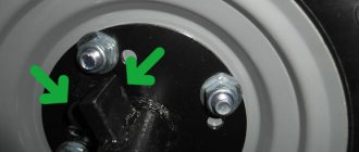
To check the nitrogen pressure in the hydraulic accumulator, remove the plug at the top of the hydraulic accumulator and install a pressure gauge on a special fitting instead of the plug (a drawing of the fitting is available in the Operating Manual for the hydraulic accumulator). Nitrogen pressure should be 50 - 55 kgf/cm2. If necessary, recharge the hydraulic accumulators with nitrogen, install the plug, check the tightness of the charging valve and the absence of nitrogen leaks.
Purpose and features
Refers to medium-tonnage, less than 14 tons of operating weight, machines. It is used in the implementation of large-scale projects for the construction of transport infrastructure facilities - roads, railways, airfields.
Performs mechanization work:
- moving soil, loosening it, picking, laying;
- formation of ditch trenches, embankments with various slopes;
- distribution of inert materials along the road surface;
- snow removal
Unit features:
- The wheel formula is 1x2x3 - 3-axle, with a pair of driving axles and one steered.
- Works on soils from category I to III at temperatures from +40° C to -40° C.
- A full-rotation grader blade driven by a worm gear ensures surface profiling when moving backwards.
- Forms slopes with an angle of 90 degrees.
- The articulated frame provides strong grip on unstable soil and inclined planes of the work site.
- Possibility of using 15 types of attachments.
- It is possible to install additional mechanisms on the front and rear semi-frames with wide parameters in the horizontal and vertical planes and with extension to one of the sides, which expands the technological capabilities of the machine.
- Full visibility of the work site from the cab, additional headlights and a flashing beacon.
- Hydraulic control of working equipment.
- Optional installation of electronic control systems for components and assemblies, a GLONASS module, automatic leveling, a video camera for monitoring the rear sphere, and a device for centralized lubrication of articulated joints.