A grab (from the German “greifen” - “to grab”) is a device intended for pulling/loading pillowcases (dust-like, loose, lumpy) and other piece goods. They can be divided into a couple of types: grab buckets for digging up soil and grab grips, necessary for unloading/loading operations. The former are often used for digging wells or cleaning wells, while the latter are employed in auxiliary work for moving various cargoes in various industries (from construction to shipping).
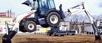
Excavators, loaders, as well as cranes can be equipped with grab equipment - grabs are installed on their lifting boom.
Control of such a mechanism comes down to two simple actions - capturing the load with the jaws of the device and its direct movement. Depending on the type of control, these mechanisms can be rope-based or motor-driven (driven).
Description
The device is a device consisting of a large iron scoop attached to a load-lifting crane and used to grab and unload material lifted by the crane - sand, earth, rocks, scrap metals.
Grabs are also working equipment for mechanical and hydraulic excavators and are used in the development of soils below and above the parking level, as well as some other types of work - digging deep pits, cleaning ponds and canals.
Options
The value of the crane's lifting capacity (denoted by " Q
"), equipped with a grab, the masses of the cargo and the grab are included. The scooping ability of the grab depends on the ratio of these masses. In this regard, bulk cargo handled by a grab is divided according to bulk density into the following groups:
The lifting capacity of a grab is determined by weighing the material after a test scooping performed by the owner of the grab before using it for handling cargo of a given type (brand, grade). Test scooping is carried out from the horizontal surface of freshly poured soil. The grab ropes must be protected from chafing by the material grabbed by the grab.
The grab blocks are positioned and constructed in such a way as to prevent spontaneous opening and loss of ropes from the groove of the block.
Excavators[ | code]
Rope grabs | code
On mechanical cable excavators, both double-jaw grabs and grabs with a large number of jaws are used - the number and shape of the jaws depend on the type of material being handled. However, the basic diagram of their operation does not differ from the diagram of a double-jaw grab.
Description | code
For a grab used on a mechanical excavator, a dragline lattice boom is used. Three types of grabs are produced for excavators: light, medium and heavy. In this case, the mass of the grab used should be greater, the denser the soil. However, the heavier the grab, the less soil it can lift for a given equipment stability, which affects its productivity.
Device | code
To prevent twisting of the ropes and significant swinging of the grab when turning the platform, a pull-out device called a damper is used. The damper acts on the bucket with a pull rope. A constant rope tension, independent of the position of the grab, is created by the weight of the load moving inside the boom along the guides, to which the rope bending around the blocks is attached. Some excavators use a friction mechanism for opening the bottom of the bucket, on the drum of which a rope is attached.
Advantages and disadvantages | code
The disadvantage of the rope grab is the inability to develop dense soils: the load from the mass of the grab is not enough to crash into the ground.
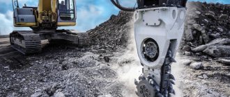
Hydraulic grabs | code
On hydraulically driven excavators, special rigidly suspended grabs are installed, which are attached to the handle instead of a bucket.
Advantages and disadvantages | code
The main advantage is the ability to create the necessary pressure when cutting into the ground and, regardless of its mass, to develop dense soils.
Rope grabs
Single rope grab
Single-rope grabs are replaceable lifting devices and can be hung on the hook cage of any crane of the appropriate lifting capacity. The rope of this type of grab is both lifting and closing. The main design feature is the presence of a lock connecting the holder to the traverse. The clip and traverse can be made with pulley blocks. The capacity of this type of grabs is from 0.5 m³ to 2.0 m³.
Principle of operation
The following are the stages of the work cycle of a single rope grab.
Advantages and disadvantages
Advantages:
- quick change;
- ability to work on any crane.
Flaws:
- strong impacts on the stops when opening the jaws;
- reduction in lifting height (due to the fact that the length of the rope removed from the pulley reaches 2.5 m);
- manual control of the opening of the grab jaws.
Double-rope
Device
The two-rope grab has jaws that are pivotally connected to the lower crossbar and with the help of rods with the head. The lifting rope, which is attached to the head, is designed to raise and lower the grab using a lifting winch. A trailing rope connected to the lower beam, which passes through a hole in the head and is fixed to the drum of the trailing winch. This rope is designed to open and close the grab jaws. To increase the cutting forces on the edges of the jaws and to better scoop up the material, the closing rope is stored in a pulley, the clips with blocks of which are attached to the lower traverse and the head. Winches have independent control.
- According to the type of drive, winches of two-rope grabs with a single-motor and double-motor drive are distinguished. In a single-engine grab winch, both drums are served by one engine and driven by clutches. In a twin-engine model, each of the drums is driven by a separate engine.
Drawing No. 1
Principle of operation
- The working cycle of a two-rope grab includes the following operations:
Drawing No. 3
If you continue to operate the closing winch after closing the jaws, the grab along with the load will be lifted on one closing rope, which will be overloaded. Lifting the grab on one trailing rope is prohibited, as this leads to rapid wear of the rope.
To avoid overloading the closing rope, semi-automatic grab control is used, in which the lifting winch is automatically turned on at the moment the jaws close. Grab capacity ranges from 2 m³ to 20 m³. The control of the ropes and provision of their tensions and speeds necessary for the normal operation of the grab is carried out by grab winches.
Advantages and disadvantages
- The main advantages are automatic operation and high productivity.
- Disadvantages are the need to have two winches and the inability to quickly replace the grab with another load-handling device.
Four-rope grab
Double rope grabs can be equipped with two, three or four ropes, but the operating principle remains the same. Four-rope grabs belong to the group of two-rope grabs. They are made with two lifting and two closing ropes.
Raking grab
Raking grabs are designed for scooping material, for example, from wagons, ship holds, etc. In a four-rope raking grab, the trailing ropes form a horizontal pulley.
Device
Supporting ropes bypass blocks on a traverse connected to the jaws by means of rods. The grab is closed when the closing ropes move upward; the grab is opened in a suspended state when the closing ropes are stopped and the supporting ropes are moving upward. The jaw span when open is up to 8 m.
Buckets and pliers: differences in grips by type of jaw
The shapes of the jaws determine what type of materials the gripper is designed to work with:
- Bucket grabs are used for digging work and are used in mining. They often have to work with dense soil, therefore, the edge of the bucket can be additionally equipped with pointed teeth;
- Pincer grabs are designed for loading round timber, various pipes (both metal and plastic), and working with scrap metal;
- Fork grabs are usually used in the agricultural sector - they are convenient for loading hay, silage, and other loose or fibrous materials.
Various bulk/small cargo (especially those that can leak) are loaded using closed (or semi-closed) grab buckets. It is their tight closure of the blades that prevents the load from being lost.
Also, grippers may differ in the trajectory of application. Digging machines are adapted for a pronounced acute angle of cutting into the working surface, while loading machines are sufficient to work at a right angle.
Among other things, some grabs can be multifunctional and made to suit specific needs. As a rule, such models are equipped with a grab rotator, which allows them to be used for both digging and loading.
Drive grab
Grab cranes use motor-driven grabs mounted on a hook cage with a single-drum winch. Motorized grabs can be used on a crane of the appropriate lifting capacity, but they have a greater mass than double-rope grabs. Controlling such a grab during unloading is simpler than using a single-rope grab. The design of the drive grab contains only support ropes.
Device
The grab has an upper head in which the drive is mounted, and hinged jaws.
The drives are available in different versions:
- electric hoist with chain hoist.
- lever devices.
- hydraulic cylinders.
In these grabs, the closing mechanism is built into the design of the grab and is a rope winch installed on one of the traverses, or a lever-screw or hydraulic system that tightens the traverses. To power the drive, a cable current supply is required.
The drive of the closing mechanism can also be performed on the upper traverse. The center of gravity of a grab of this design is shifted upward.
Advantages and disadvantages
- Advantages: compact design and preservation of the crane’s lifting height.
- The disadvantage of grabs with a locking mechanism on the upper traverse is the deterioration of the stability of the grab when scooping from a slope due to a shift in the center of gravity.
Instead of an epilogue
The market analysis shows that this segment is quite saturated with various models and allows you to make a reasonable choice. If we focus on foreign brands, then the secondary market is more filled with them. Russian brands occupy an average position in the primary market, but only due to their reduced prices. In any case, the choice between used and new equipment should be made based on current tasks and the expected duration of use of the device. It is worth noting that it is completely impossible to navigate prices by monitoring online sites for new models - you can find out the price for new copies only by requesting it directly from the dealer or manufacturer. In turn, the search for the required model on the secondary market is extremely limited; as a rule, it is not possible to assemble a grab grab completely “for yourself” and you have to search for a long time for the required equipment in a ready-made version.
Device
The load-handling organ of a grab crane consists of jaws designed for scooping. During operation, the jaws open and close. The structure of the grab jaws consists of two vertical walls and a bottom, forming a separate container in which material is lifted and transferred. The jaws are articulated with a supporting traction beam, which allows them to be controlled using supporting and closing ropes. Grab winches provide tension on the ropes and regulate their speeds.
Grab cranes are designed in the same way as overhead cranes. The working mechanism is fixed to a movable metal structure. In cross section, it looks like a U-shaped beam, which is why it is usually called a bridge, or a crane beam. Trolleys moved along rails or belts of the crane beam are designed for lifting and transporting goods along the span. To ensure movement, the carts are equipped with special running wheels-rollers. The diameter and rotation speed of each roller are different, proportional to the maximum and minimum radius.
Purpose
Grab cranes, thanks to the specific design of the load-handling device, are designed for transporting difficult-to-scoop types of cargo. The scooping capacity of the grab is established at the design and testing stage of the machine. The actual scooping capacity, that is, the mass of the load, is related to several parameters:
- bulk density of the material;
- width of jaws and distance between cutting edges;
- compliance of the load with the introduction of the grab;
- material compaction coefficient.
To determine the scooping capacity of the grab, the data from GOST 24599-87 Rope grabs for bulk cargo are used. The standard also defines the main transported materials:
- dry heavy sand;
- lead and iron ore concentrate;
- coal;
- gypsum lumps;
- alumina;
- wheat grain;
- coal coke;
- powdered apatite.
Properties of raw materials, such as density, hardness, size of fractions or pieces, affect the performance of the crane, since they have different resistance, requiring adjustment of the forces and methods of scooping control. For example, if the support ropes are under strong tension, it is impossible to move the upper beam. As a result, the machine scoops up a small amount of material.
Application area
The main part of the crane is the console. This is a beam located in the horizontal direction. A cart with a hook moves along it. The mechanism rises and lowers, and the trolley with the load moves only horizontally. If it is mounted on a wall, the mechanism is called a wall-mounted jib crane.
The cantilever beam is attached to a vertical column. Column-mounted jib cranes take up little space, are easily disassembled and transported to the desired part of the production area. They replaced bridge structures that stood on 2 supports and took up a lot of space on the site.
Console devices rotate around the column left and right, sometimes rotate 360°. Turns are carried out manually - the KKR is mechanical, or the turning mechanism can be equipped with a motor with a gearbox. The console uses a trolley that moves using cables.
Lifting mechanisms have found their application in warehouses, in the construction of household and industrial facilities, and at airports. Jib cranes are often used in production shops as additional equipment. With its help, heavy workpieces are moved to machines. In workshops it is also found standing on a column against the wall or in the middle part of the room.
If it is necessary to work with light loads, manually controlled structures are used - mechanical KKR. For heavy loads, there are console cranes of 2 tons, cranes with a lifting capacity of 5 tons, 10 tons and more. They are often equipped with electric traction and a hoist winch. To ensure greater stability, a cantilever double-arm crane unit is used.
Such equipment is produced upon individual orders. It can have a console of greater or lesser length, change the angle of rotation of the mechanism, the height of the load, and the load capacity of the device.
Notes
- Grab
- article from the Great Soviet Encyclopedia. - ↑ 1234567891011121314151617181920212223242526272829
Load-lifting and transporting machines at construction materials factories/V. P. Balashov
- M: Mechanical Engineering - 1987 - 384 p., ill.
- Grab // Explanatory dictionary of the Russian language: in 4 volumes / ch. ed. B. M. Volin, D. N. Ushakov (vol. 2-4); comp. G. O. Vinokur, B. A. Larin, S. I. Ozhegov, B. V. Tomashevsky, D. N. Ushakov; edited by D. N. Ushakova. - M.: State Institute "Soviet Encyclopedia" (vol. 1): OGIZ (vol. 1): State Publishing House of Foreign and National Dictionaries (vol. 2-4), 1935-1940.
- ↑ 1 2 3 4 5 6 7 8 Berkman I.L., Rannev A.V., Reish A.K.
- Universal single-bucket construction excavators, School - M: Higher School, 1977, 384 pp., ill. - ↑ 1 2 3 4 5 P. N. Ushakov, M. G. Brodsky
- Ref: Cranes and elevators of Industrial enterprises, 1974, 352 pp., illus. - ↑ 1 2 3 4 5 6 7 8 9 P. Z. Petukhov, G. P. Ksyunin, L. G. Serlin
- Special cranes - M: Mashinostroenie, 1985, 248 p.
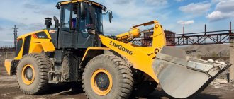
JCB Attachments Grab Bucket
Information
is ready to offer a wide range of JCB attachments, hand tools and special equipment. All products are made in the UK. The status of an official partner allows us to set minimum prices for grab buckets and other equipment, as well as constantly have in stock all the items listed in the catalog. Grabs for excavators and other attachments that can be purchased at LONMADI are covered by the manufacturer's warranty. The clamshell bucket of an excavator or manipulator is a simple and effective lifting device used for lifting and loading bulk materials, as well as excavating developed soil from deep pits. In the manufacture of modern grippers, a powerful hydraulic drive is used to ensure reliable retention of the load. Some models can be equipped with round jaws, suitable for digging wells.
Grab grabs for scrap metal and other cargo on sale have larger hydraulic cylinders. The design of the grabs is reinforced in areas experiencing the greatest loads. All important components are reliably protected, which prevents accidental damage when working with hard materials. Flexible hoses, which are installed on grab grips for logs and scrap metal, have increased thickness and are made of materials that are abrasion-resistant and do not degrade under the influence of aggressive substances, high temperatures and UV radiation.
At the request of the customer, the grab can be equipped with telescopic equipment, allowing it to work in pits up to thirty meters deep. When using this type of equipment, it should be noted that the use of extended grab buckets for cranes or excavators requires careful safety precautions from operators. Before starting work, you must make sure that the surface on which the equipment is located provides a sufficient margin of stability.
Advantages of ordering grabs for excavators from us
Would you like to clarify the characteristics or cost of equipment? Contact the company's consultants. We are ready to help you select a grab bucket for an excavator or manipulator at an affordable price. All equipment is supplied directly from the warehouse and is regularly in stock. LONMADI has a network of representative offices that allows you to purchase special equipment, equipment and hand tools outside of Moscow.
From the company you can not only buy a hydraulic grab and other attachments. Do you need professional maintenance and repair services? LONMADI has its own service center, which has everything necessary to carry out high-quality diagnostics and repair work of any complexity. The company uses OEM parts and consumables recommended by the manufacturer. Customers doing their own repairs can purchase spare parts for clamshell buckets separately.
Specifications
The main parameters of a grab loader are bulk density, which is measured in kilograms or tons per cubic meter, and lifting capacity. The latter is designated by the letter Q.
This parameter includes the weight of the grab and the load itself. The scooping capacity of the unit depends on the Q ratio. There are four classes of grab loaders:
- Very light. Their bulk density ranges from 400 to 630 kilograms per cubic meter. Typically such loaders are used for coal dust and lime. Load capacity index – 0.37.
- Lungs. These units are used for loading dry slag, alumina, chalk, medium crushed stone and coal of various grades. Bulk density ranges from 800 to 1000 kilograms per cubic meter. Load capacity index – 0.4.
- Average. Used for fine clay, alabaster, and limestone. Also, this type of tractor (middle class grab loader) can be used for transporting broken bricks, large crushed stone and cement. The bulk density of the unit is about two tons per cubic meter. Load capacity – 0.42 Q.
- Heavy. These loaders are used for hard rock. Load capacity – 0.45 Q. Bulk density varies from 2.5 to 3.2 tons per cubic meter.
DIY process
You can make a grab yourself, saving on the purchase or rental of expensive equipment. In terms of efficiency, a homemade grab for cleaning wells will be no different from a mechanized one, since sludge is a soft substance, which is also in a semi-liquid state.
Grab device diagram
Required material
To make the device you will need:
- steel sheet 2 mm thick (any one will do, for example, the common ST3);
- two steel pipes about 60 mm long, one of which fits freely into the other, but does not dangle;
- a chain or steel cable three times longer than the depth of the well, plus 1.5–2 m for reserve;
- welding machine, electrodes and welder’s mask;
- additionally - a drill, a grinder for metal, mounting bolts (you can do without them).
Structurally, any homemade grab consists of two toothed buckets, which, when closed, form a semicircle when viewed from the front. They are connected to each other by brackets welded to a drum made of pipes inserted into one another - the first bucket to the outer pipe, the second to the inner one. Additionally, ballast is welded onto the bucket plates, approximately 5 kg on each side. One chain is wound on a drum, other chains or cables are threaded through the eyes on the plates - they open the “jaws”.
Step-by-step instruction
Construction process:
Homemade grab - drawing
- For a manual grab with a capacity of 1 bucket, a steel plate 550 mm long and 220 mm wide is sufficient. It is cut into 2 equal parts, and the cut either immediately goes in a zigzag, forming teeth, or the strips with teeth are welded subsequently.
- On the first bucket, the teeth should be at the end of the plate, on the second, they should be welded on the outside so that when closed they overlap, one on top of the other.
- For the sides, trapezoidal plates with a height of 220 are taken. They are welded to the main plates, which will form a sliding bottom, with a distance of 50 mm from the line of the jagged edge of the side. In this case, the side plates are butt-welded to the first bowl, and to the second - from the outer edge of the side, so that when closed they overlap one another.
- Ballast is welded from below or to the side.
- After this, brackets or “ears” are cut out of the remaining metal, 2 for each half of the sliding bucket. They are welded to the narrow part of the trapezoidal sidewalls.
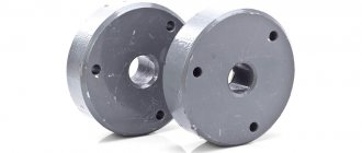
- The hinge is made from two metal pipes. The smaller diameter tube should protrude slightly from the larger one.
- Thread the hinge between the halves of the “mouth”. A bowl of smaller diameter is welded through “ears” to the outer pipe (so as not to catch the inner one by welding), a bowl of larger diameter is welded to the inner pipe.
- They check. The structure should move freely, the toothed plates should close, the “jaws” should slightly overlap one another.
- The main chain is welded or otherwise attached to the drum. In both bowls, holes are made on the side opposite to the teeth, into which chains or cables are also threaded (can be welded or attached differently).
- The do-it-yourself grab bucket is ready.
Double rope grab dimensions