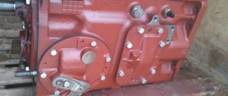
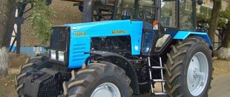
Gearbox T 170
Gearboxes T-170, T-130, T10M, B10M
are an important component of these special vehicles from.
These tractors and bulldozers are considered indispensable units for agricultural and construction work, and they are also often used for mining. Since Russia is rich in spacious territories, it is impossible to do without such heavy equipment, unlike Europe, where mini tractors will do just fine in more modest areas. But for companies that mine diamonds, gold and coal (for example, in Yakutia, Siberia or the Far East)
, with such large-scale tasks, the above-mentioned special vehicles even look small. Therefore, manufacturers do not stop working on developing larger models.
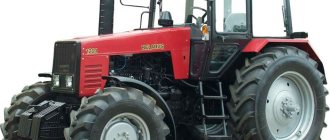
T-170 tractor is still in demand on the domestic equipment market
, which has been produced since 2003 and has several modifications.
The T-130
is also a fairly common unit, in particular due to the fact that in Soviet times all equipment was very reliable and durable.
More modern modifications of bulldozers are those that began to be produced after 2003. These are machines such as T10, B10, T10M, B10M
, as well as a specialized version
T10MB
, which is additionally equipped with attachments (pipe layers, pile drivers, bar installations or auger equipment).
REASONS FOR THE POPULARITY OF THE T 170 GEARBOX IN THE SPARE PARTS MARKET
Along with a properly functioning diesel engine and tracks, the gearbox
is one of the most important factors in organizing the performance of the entire tractor.
In the domestic spare parts market, gearboxes are quite a popular product. This is due to the fact that most customers prefer to work with old tractor models, restoring them by replacing the most important components. At the same time, newer special equipment, both original and manufactured under license, will cost about 4.5-6.5 million rubles
, taking into account the recycling fee. Most construction and other companies simply cannot afford such a machine.
Thus, we can say that the gearbox is a popular replacement unit in a tractor produced by ChTZ, which is a four-shaft mechanism (otherwise it can be called a three-stage gearbox or a five-row planetary mechanism). It is equipped with control levers and has a total weight of about half a ton. The cost of such a device averages 70-150 thousand rubles (the price depends on whether the box is new or refurbished).
VARIETIES OF T 170 Gearbox
Four-shaft gearbox
Designed specifically for cars that operate with a manual transmission. It has two levers to control braking and turning, as well as shafts and a number of gears. The upper shaft is the weakest, while the lower one has the highest torque and high power. The design also provides two intermediate rollers.
The box is equipped with several continuous gears, which organize 8 forward gears (both normal and accelerated), as well as 4 reverse speeds. In addition, the device contains a gear, which, depending on its diameter, makes the box quiet or fast. It is used as part of the T-10, B-10, T10M, B10M, T-130, T-170, B-170 tractors, including swamp versions of the units.
Even though the hydromechanical transmission
gained its popularity a long time ago, the four-shaft gearbox is still a hot commodity. In most cases, this is due to the fact that manufacturers who assemble equipment under license supply it with a mechanical transmission. Moreover, the number of such assemblers is quite large, because the original manufacturers experience difficulties related to pricing policy and production time.
Planetary box
used along with hydromechanics (1-stage three-wheel transformer). Its main advantages are the smooth traction of the unit, the presence of three speeds when moving forward and in reverse (the gearbox includes five planetary gears, which are connected to five brake devices). A special feature of the gearbox is the presence of a single-stage gearbox, which connects the planetary mechanism and the main bevel gear.
Checkpoint swamp 50-12-12(Opens in a new browser tab)
Gearboxes T-170 T-130(Opens in a new browser tab)
Gearboxes T-170 T-130(Opens in a new browser tab)
Gearbox 50-12-12 swamp (with 642 gears) (Opens in a new browser tab)
Tractors T-130, T-170, T-10 have several versions of gearboxes, among which the most common are: 24-12-1SP
(intended for high-speed T-170 vehicles with a 320mm gear or low-speed with a 642mm gear),
20-12-9SP or 20-12-9-01SP
(with locked 1st gear or not, used in a T10MB swamp vehicle equipped with mechanics ),
50-12-8SP and 50-12-12SP
(for special equipment T-170.00 and its subsequent model T-170, respectively).
For machines with hydromechanics, boxes of types 64-12-3-02SP and 64-12-3-04SP
. This applies to those tractors that were produced after 2003 (these are T10M and B10M units).
It must be remembered that more advanced gearboxes are usually not installed on older versions of tractors.
This is due to the fact that an increase in torque on equipment can lead to rapid wear of the gears, and at the same time the gearbox may not improve traction characteristics. That is why, when choosing a box that does not match the model, it is better to seek help from a professional.
Tractor T-130
The T-130 tractor is used to carry out a whole range of road, planting, earth-moving and reclamation works. This model is also actively used on construction sites and in agriculture (plowing, sowing, cultivating).
The T-130 is the brainchild of the Chelyabinsk Tractor Plant, which has been operating since 1933. This company is positioned as one of the largest manufacturers of tracked vehicles. Subsequently, such tractors were used as the basis for the construction of bulldozer-ripper units, pipe layers and other variations of equipment. The main direction of the Chelyabinsk Tractor Plant is the production of tractors and bulldozers of the most popular traction classes (10-15 tons).
The T-130 model was put on the assembly line in 1969, and in 1988 mass production was officially discontinued. Despite this, the released models continue to be popular due to their long service life and high maintainability.
RULES FOR ASSEMBLY OF TRANSMISSIONS
When installing a gearbox, certain requirements must be taken into account. First of all, you need to take care of lubricating the outer surfaces of the bushings for sliding bearings, rubbing surfaces, as well as the smooth holes of the gears using transmission oil. Roller bearing rings (internal and external)
cylinder-shaped must necessarily belong to the same group.
In this case, before installation, ball and roller bearings must be preheated in an oil bath to a temperature of approximately 80 to 100 degrees
. The front cover, as well as the body, are marked with identical serial numbers on their tops, and these are machined during the assembly process.
The lower gearbox shaft is equipped with a bevel gear
related to the main gear.
Dismantling of these parts is strictly prohibited. The levers that change gears inside the gearbox must be moved from neutral to the left or right side, taking into account the evenly increasing force created by the resistance of the springs. And the shafts in the system, along with their forks, must move freely, while their neutral and working positions must be clearly fixed. The rotation of the levers is also free
with no jamming in all the provided locations that provide for the activation of a particular gear. In this case, the rollers do not move if the latches are locked.
When one shaft moves from the neutral position
, the remaining shafts must be firmly held in their positions by means of a ball lock.
The studs as part of the structure must be mounted on thickly ground red lead made of iron. When assembling, you also need to take into account the gap
between the outer race of the bushings and the gear hole, which should not exceed 0.3 mm (usually it is 0.12-0.21 mm). And the distance between the gear bushings and the spline side of the upper roller should be 0.146-0.424 mm (no more than 1 mm).
The assembled gearbox is equipped with a bevel gear, which is a spare part. When changing the gearbox, it is also necessary to replace this part, the serial number of which is indicated on the gearbox housing.
Shift forks with drive rollers are located in pairs in special bores of the box body and are covered on top with two switching mechanisms, which are secured with studs and nuts on two inclined platforms of the box body.The right control mechanism 70 provides one of three ranges, and the left 55 provides one of four gears. Both mechanisms operate independently of each other.
A driver 68 with a blind groove is secured to each drive roller 64 with a screw 69 with a conical end. Two adjacent drivers form a closed groove in which the end of the intermediate lever 57 is located. If both forks are in the neutral position, the end of the intermediate control lever can freely fit into the groove of either driver. When moving the movable gear coupling, when the intermediate lever is pumped in the longitudinal direction, the driver and special lugs in the upper part of the other driver form a closed groove from which the lever cannot exit until both drivers are in a neutral position, i.e., they are located against each other.
The intermediate lever is bolted 59 to an axis 58; this axis easily moves in the tides of the shift mechanism housing. In the upper part, the intermediate lever has a cylindrical well, into which the lower end of the control levers 62 fits. The lever has a spherical thickening in the middle part, allowing it to move in spherical covers. The control lever has a seal 61. It is returned to the neutral position by two springs 60, resting on the support ring.
To prevent the gears from turning on or off during operation, there are four clamps 67 located in the housings of the switching mechanisms in pairs, which are pressed by springs to the grooves of the drive rollers 64 of the forks. The clamp rollers 66, connected by the lever 65 to the clutch, form a locking device that locks the clamps and, accordingly, the shift forks in the position they occupied when the clutch was engaged.
When a particular gear is engaged, the fork moves left or right. The lower conical end of the clamp slides along the conical groove of the drive roller (there are three grooves on each roller) and rises, overcoming the force of the clamp spring. In this case, the upper end of the clamp falls into the groove in the clamp shaft 66. This groove is located above the clamps if the clutch is disengaged. Only under this condition can the latch rise, releasing the drive roller and fork. When the clutch is engaged, the clamp roller is rotated so that the outer diameter of the roller is located opposite the upper ends of the clamps. This position of the clamp roller does not allow the clamp to rise and the drive roller with the fork to move.
If any gear is not fully engaged, the corresponding lock does not fit into the groove of the drive roller and remains in a raised position. When the clutch is engaged, the edge of the groove of the clamp shaft, resting against the shank of the clamp, can break it off if the safety spring does not work. The spring rotates the detent shaft, but when resistance occurs, the shaft stops and the spring usually begins to compress. The compressed spring ensures that the clutch is completely disengaged.
To prevent two gears from engaging simultaneously, a ball lock consisting of two balls 63 and two cylindrical grooves is installed between two adjacent drive rollers. When one of the rollers moves, the cylindrical surface of the groove of this roller pushes out a ball, which presses the second ball into the groove of the other roller.
The gearbox is attached to the front wall of the onboard clutch housing with 12 studs. The box body is centered in the hole in the front wall of the side clutch housing with the outer ring of a special roller bearing. The rotation of the gearbox relative to the longitudinal axis is determined by the alignment pin.
All gears are made of chromium-nickel steel, cemented and hardened to high hardness. The lateral clearance in the meshing of the gearbox gears is 0.2-1 mm.
The rear end of the driven shaft is integral with a 13-tooth small bevel gear, which is in constant mesh with the final drive driven bevel gear.
To ensure correct installation of the driven shaft bevel gear relative to the mating plane of the box, steel shims are installed under the flange of the front ball bearing housing of the driven shaft. Distance from the rear plane of the driven shaft to
the mating plane of the gearbox housing should be 83.8–84.0 mm (dimension b in Fig. 59).
To prevent oil from leaking, a non-contact seal is installed between the gearbox drive shaft and the bearing cap, consisting of an oil drain thread, a specially shaped reflector and a system of drainage holes. The runout of the reflector relative to the drive shaft should be minimal.
Oil is poured into the box body through the neck located on the rear right side of the tractor on the top sheet of the clutch housing, up to the mark marked on the ruler. Check the oil level using an oil dipstick.
There is a hole in the rear wall of the gearbox housing through which oil from the gearbox can flow into the bevel gear compartment, forming a common oil bath.
But the oil does not completely flow from the gearbox housing into the main gear compartment when the tractor is moving uphill, and does not flow from the main gear compartment into the gearbox housing when starting the tractor from the mountain.
To drain the oil, there is a hole at the bottom of the gearbox, the plug of which is equipped with a magnet to catch metal (steel) particles from the oil.
On a swamp tractor, the gearbox control mechanism differs from that described. The neck of the mechanism is attached in a cantilever fashion with studs and nuts to the modified body of mechanism 3 (Fig. 61). At the same time, the control roller 4 is longer than that of the base model, and instead of a solid intermediate lever 8 there are upper and lower intermediate ones.
The rear end of the drive shaft is a dependent power take-off shaft from which up to 100% of engine power can be removed.
It is not recommended to make any adjustments to the gearbox during operation.
ASSEMBLY PROCESS OF TRANSMISSION T-170, T-130, T10M, B10M
To begin, the upper shaft is installed into the device, with its side with the key pointing down
.
After this, the ring, bushings, gears and special couplings are installed one by one, while the grooves of the bushings and couplings, when installing them, must be aligned with the machined channels for supplying the lubricant. Next, the clamp is attached to the mechanism along with its spring and bushing
, the flat of which is located towards the lower roller, aligning the holes for lubrication. After this, the upper shaft is mated with another gear and bushing.
All installed parts are moved together, installing sealing gaskets
, which at the same time provide a gap of no more than 0.3 mm for the subsequent connection of another bushing and bearing.
These seals, characterized by a thickness of only 2 mm, are attached to both ends of the bag. Before pressing onto the shaft, the above-mentioned bearing is preheated to 80-90 degrees, after which a lock washer is placed on the roller and tightened with a special nut (tension torque is 450-550 Nm
).
As a result, the specified washer bends onto the edge of this nut
, making it possible to rotate the roller in the opposite direction.
The process is completed by heating the other bearing, which is also pressed until it stops. As a result, in a fully mounted upper shaft, the gears can rotate freely
on their bushings, and the couplings move without jamming.
After the upper one, the first intermediate shaft
, while its splined surface should be directed upward, and then bushings with gears, rings, bearings and a spacer are put on it, tightly attaching all parts to the shaft with a stop.
Then a special ring is put on, into which a bearing heated to 90 degrees is pressed. Next, a lock washer
, towards which the nut is pulled with the machined side (with a tightening torque of 450-550 Nm).
The process is completed by turning over the intermediate roller
, after which a preheated bearing is put on it.
After the first, the second intermediate shaft
gearboxes
It is attached to the device, having previously turned the threaded end upward, and is mated with a number of gears and bushings, which move everything together until it stops. Following this, a gap of approximately 0.05-0.3 mm is created between the end of the gear and the inner ring of the bearing by installing a series of 2 mm thick spacers on both sides of the device. As with other shafts, a heated bearing
, after which the roller is inverted, allowing another bearing heated to the same temperature to be mounted. The design is completed with a retaining ring.
Following the upper roller and two intermediate ones, the lower one
, the bevel gear of which is initially directed downwards.
After this, the bearing, preheated to 90 degrees, is tightly mounted on the shaft, allowing it to be installed with emphasis on the shoulder. Next, a set of bushings, gears, as well as a spacer and ring are installed one by one, with all the parts moving tightly
together. Thanks to this, it is possible to attach special 2mm thick spacers, which, when mounted correctly, provide a gap of 0.05-0.3mm (as on other rollers) between the bushing and the inner race of the bearing. It, like similar elements in the system, is initially heated to the above temperature by dipping into an oil bath.
It is important to remember that when assembling the lower roller, it is necessary to ensure that the groove is aligned with the splined part of the coupling with the holes that are machined on the roller for supplying lubricant. This gearbox shaft is mounted in the system simultaneously with the corresponding bevel gear of the main drive, which is checked for gearing.
9.2.2. Mechanical transmission of the T-170 T10 tractor
The tractor's mechanical multi-stage transmission consists of a clutch, a gearbox with switching mechanisms, a final drive, final clutches, brakes, final drives, a lubrication system and a transmission control system.
The clutch (Fig. 9.28) of dry friction, permanently closed with a hydroserved engagement drive with two driving and two driven disks, is mounted on a diesel engine. The driven disks rotate together with the drum on closed bearings mounted on a journal attached to the diesel crankshaft. The drive and pressure disks rotate together with the flywheel.
Rice. 9.28. Clutch:
1 – pressure springs; 2 – flange; 3 – pressure disk; 4 – master disk; 5 – driven disk; 6 – cardan shaft coupling; 7 – gear drum; 8 – diesel flywheel; 9 – axle; 10 – nut; 11 – bolt; 12 – lever; 13 – release clutch; 14 – brake; 15 – gearbox upper shaft flange; 16 – coupling; 17 – cardan shaft; 18 – brake cover; 19 – shutdown lever (release); 20 – slider
Rotation is transmitted to the upper shaft of the gearbox through the cardan shaft and gear couplings. When the clutch is disengaged, the release clutch, moving backward, pulls three levers, which, through fingers acting on the pressure plate, compress the spring package, providing clearances between the drive and driven discs. At the end of the pedal stroke, brake 14, in contact with the friction lining with the release bearing housing, stops the upper shaft of the gearbox, ensuring shockless gear shifting.
The coupling is protected from the outside by a casing. Turning it off is facilitated by a servo mechanism included in the hydraulic tractor control system (Fig. 9.29). The clutch of swamp tractors has an extended shaft.
The clutch is removed from the tractor without dismantling the diesel engine and the upper half of the clutch housing. To do this, it is necessary to unscrew the drain pipe fitting 5 (Fig. 9.29) from the servomechanism body and disconnect the pipe. Screw the fitting back into the servomechanism body, this will protect the servomechanism piston from lowering to the non-working position and jamming. Remove the lower half of the clutch cover. Disconnect the clutch release lever 19 (Fig. 9.28) from the linkage to the servo mechanism, the bolts securing the clutch to the upper gearbox shaft and the brake cover 14 to the clutch. Together with the clutch, move the propeller shaft 17 all the way towards the release clutch 13. Remove the clutch 16, tighten the flange 2 and the pressure plate 3 through the holes in the flange with three M12x35 bolts. Remove the bolts securing the flange to the flywheel, holding the coupling from below or through the hatch in the upper half of the casing. Move the clutch towards the gearbox and remove it downwards. Install the coupling in the reverse order.
Rice. 9.29. Hydraulic control system for tractor with mechanical transmission:
1 – pipe for supplying working fluid from the hydraulic tank valve to the control system pump; 2 – pipe for draining the working fluid into the hydraulic tank; 3 – pipe for draining the working fluid from the servomechanism of the onboard clutches; 4 – pipe for supplying working fluid to the servomechanism of the onboard clutches; 5 – pipe for draining the working fluid from the clutch servo mechanism; 6 – pipe for supplying working fluid to the clutch servo mechanism
The gearbox (Fig. 9.30, 9.31) has 8 forward and 4 reverse gears, is mounted in a separate housing and attached to the front wall of the side clutch housing. The gearbox is four-shaft with constant mesh gears. Each shaft is double-supported on three rolling bearings, of which the front one is ball bearings, and the rest are roller bearings.
On the intermediate shafts, the gears are mounted on splines. On the upper and lower shafts, the gears rotate freely on bushings.
To install the power take-off shaft drive, the upper and second intermediate shafts are made with splined shanks for connecting the PTO drive and creeper. The maximum power output from the gearbox shaft, taking into account losses on the pump drive (without load) of the hydraulic system for controlling attachments and transmission, see table 10.1.
Table 10.1
| Diesel power, hp | Maximum power output from the gearbox shaft at the rated speed of the diesel crankshaft, kW (hp), not less |
| 180 | 125+3,7 (170+5) |
| 170 | 117,6+3,7 (160+5) |
| 140 | 95,6+3 (130+4) |
Rice. 9.30. Transmission:
1 – lower shaft; 2 – body; 3 – gears of 2nd gear; 4 – 1st gear gears; 5 – gears of the 3rd gear; 6 – forward gear; 7 – coupling; 8 – 4th gear gears; 9, 21 – reverse gear; 10 – cover; 11 – gasket; 12, 28 – nut; 13 – bearing housing; 14 – second intermediate shaft; 15 – lock washer; 16 – first intermediate shaft; 17 – oil deflector; 18 – flange; 19 – upper shaft; 20, 31 – ring; 22 – gears of normal range; 23 – accelerated range gears; 24 – clamp; 25 – oil pump drive gear; 26– plug; 27 – stopper; 29 – bushing; 30 – cover; C – installation size of gear shift forks (21.5 ± 0.8) mm; D – installation size of gear shift forks (27.5 ± 0.8) mm
Gears are switched by two levers of the shift mechanisms: lever 6
(Fig. 9.31) gear shift and lever 15 for switching reverse and forward ranges, with the help of which the gear couplings on the upper and lower shafts are moved by the forks. On the lever for switching reverse and forward ranges there is a start blocking switch VK418 and a sound intermittent reverse signal switch VK412.
When the reverse gear is engaged, the contacts of the switch VK412 are open, an intermittent signal sounds.
In the gear shift mechanism on swamp tractors, the levers are moved forward, and the spacer, lever and roller are changed accordingly.
The front wall of the gearbox is removable.
In the gearbox of T10MB.2120-11 tractors, the first gear is blocked. The blocking is carried out using a stop bushing, which prevents the shaft and fork from moving in the direction of engaging 1st gear.
Rice. 9.31. Transmission:
1, 2 – plug; 3 – locking plate; 4 – switch VK 418; 5 – switch VK412; 6, 15 – lever; 7 – gear shift lever; 8, 13 – spacer; 9, 14 – roller; 10, 17 – switching mechanism; 11 – cover; 12 – body; 16 – lever for switching reverse and forward ranges; 18 – cover; 19 – lever; 20 – housing of the clamp roller; 21 – clamp roller; 22 – roller of gear shift mechanisms; 23 – retainer; N – gap (0.3–0.5) mm; K – size (29 ± 1) mm; L – gap (0.3–1.5) mm; M=(51–Р) ±1 mm
Lubrication system (Fig. 7.6)
The rubbing surfaces of the upper and lower gearbox shafts and the bevel gear shaft bearings are lubricated under pressure.
Pour oil into the gearbox and bevel gear compartment through the neck located on the upper plane of the onboard clutch housing (near the servomechanism). The oil pump is installed on the gearbox housing on the right. The oil filter is attached to the left shift housing. The oil cooler for the transmission lubrication system is installed in front of the diesel oil cooler.
ATTENTION! Tractors are supplied with the transmission lubrication system radiator disconnected.
The radiator is connected by rearranging the hollow bolt 4 and stop 3 in the filter housing of the transmission lubrication system.
The main gear, final clutches, brakes and final drives are the same as for tractors with hydromechanical transmission (see subsection 9.2.1).
INSTALLING ROLLERS WITH THE FRONT COVER OF THE TRANSMISSION
When the assembly of all gearbox shafts (upper, lower and a pair of intermediate ones)
All these elements are installed inside the device.
To begin, attach the upper shaft so that the distance between the surface and the ends of the gear is approximately 126 mm (±0.06). This gap can be adjusted using a special template
, due to which this size provides a distance G equal to 126 ± 0.2 mm.
the first intermediate roller is installed
inside the gearbox cavity, while the ends of the gear gear of the upper roller protrude in relation to the teeth of the other gear in such a way as to ensure a distance of 2±0.5 mm.
Mounting the above-mentioned rollers in the gearbox to the required dimensions is possible thanks to the use of handles. After this, the 2nd intermediate roller
is attached inside the device in such a way as to form a distance between the ends of the gear of the 1st intermediate roller and the gear of the 2nd, equal to 4±0.5 mm.
Following this, the structure is completed with a lower shaft
, after which the mentioned cover is installed on the pins, which is pressed tightly to the plane using clamps.
After attaching the gasket pack and sealing ring to the flange, it is possible to install the bearing housing into the front cover. Following this, the outer race of the bearing is firmly pressed into the housing flange on the upper shaft of the gearbox. After this, another bearing is heated
in the system, which mates with the upper roller at a temperature of about 80-90 degrees, while it is firmly attached to the other bearing. After this, an oil deflector with a key is installed in the device.
Before installing the gasket on the flange, it is first lubricated with sealant, after which a cover is attached to the bearing housing on the upper roller. It is tightly screwed to the body using fastening bolts and washers. Following this, the upper roller cover is equipped with a rubber ring, after which a flange heated to 260 degrees is pressed on. Next, a nut is screwed onto the roller with an emphasis on the specified flange, after which the structure is tightly secured with a pair of bolts and spring washers. After installing all the listed elements, you need to check the size D
, which must correspond to the specified parameter of 126±0.2. If necessary, you can use shims.
Next, a set of other gaskets is put on, along with an o-ring, onto the bearing housing related to the 1st intermediate shaft, with its subsequent installation in the front cover. The outer ring of the bearing is securely pressed into the housing with a stop, while its number on the ring is directed upward. The bearing is heated to the same temperature that was required for the installation of similar parts, after which it is firmly attached to the intermediate roller.
After this, the structure is supplemented with a lock washer, the inner tendril of which fits into the keyway, after which the nut is screwed towards the washer with its machined side (while the ends of the washer are moved towards it).
The other gasket is lubricated with the same sealing material
on both sides, after which it, along with the cover, is installed on the flange of the bearing housing.
Its position is securely fixed with bolts and washers. The gap is checked at 2 ± 0.5 mm and, if necessary, adjusted using gaskets. Following this, another sealing ring is installed in the bearing housing, which already belongs to the 2nd intermediate shaft with pressing towards the cover. The outer race of the bearing is attached to the housing with its stop in the shoulder, with the number on its race facing upward. The next bearing is heated in the same oil bath
according to all the specified rules, as a result of which it is pressed onto the shaft.
The internal antenna of the lock washer is installed in a special groove made on the intermediate shaft, after which the machined end of the nut is screwed towards it with the edges bent. The other gasket is also lubricated with sealant
, is installed together with another cover on the flange of the bearing housing on the 2nd intermediate roller.
The connections are reliably sealed using spring washers and fastening bolts
. As a result, the size should correspond to 4±0.5mm. If the parameter does not match, it can be adjusted using another set of shims.
The final round of installation of the gaskets and sealing ring takes place on other bearings, now related to the lower press-fitted roller on the front cover. The outer race of the bearing is tightly attached to the bearing housing with an emphasis on the shoulder. The last lock washer is secured in the groove using its internal tab
, after which a nut is screwed onto the lower shaft, the machined side of which is adjacent to the above washer.
Dimension D
(83.9±0.1mm) must correspond when adjusting (additional spacers can be used).
Regulation of mechanical transmission mechanisms T-170 B-10
here you will find information: about tractors T-170, T-130, B-10, and their mounted attachments, cabins of old and new cabins T-130, T-170, B-10, power plants engines D-160, D -180, caterpillar undercarriage T-170, B-10, bogie frame T-130, T-170, B-10, spare parts spare parts T-170, T-130, B-10, read articles about the repair of T- bulldozers 130, T-170, B-10.
Adjustment of the clutch, clutch servo and locking mechanism.
Regulation of the clutch and its control drives consists of ensuring a gap of 10 ± 1 mm between flange 1 (Fig. 8.20) and release clutch 6, installing the arms of the levers 2 in the same plane and ensuring a free play of 14 + 1 mm of the rod 17 (Fig. 8.21) servomechanism.
| Rice. 8.20. Clutch adjustment: 1 – flange; 2 – lever; 3 – prism; 4 – adjustment nut; 5 – bolt; 6 – release clutch; 7 – clutch release lever | During operation, due to wear of the friction linings, the gap in the coupling and the free movement of the servomechanism rod decrease. When the gap between the flange and the release coupling is reduced to 2+1 mm, which corresponds to 6+1.5 mm of free play of the servomechanism rod, it is necessary to make adjustments. To adjust the clutch: – stop diesel; – set the gearbox shift levers to the neutral position; – open the hatch of the clutch housing and unlock the adjusting nuts 4 (Fig. 8.20) of all three levers; – set (using a template) by rotating the adjusting nuts 4 of the three levers a gap of 10 ± 1 mm between flange 1 and release coupling 6 and a gap of 0 to 0.2 mm between levers 2 and the flange of release coupling 6. |
Adjusting the clutch servo mechanism.
After adjusting the gaps in the clutch, you should make sure that there is a gap A of 0.5 to 1 mm between the rod 17 (Fig. 8.21) of the servo mechanism and the pressure lever 5. The gap is set by rotating stop 11 on the pedal column. Measure the free play of the rod 17 (the rod sinks when the pedal is pressed). The stroke should be 14+1 mm.
| If necessary, adjust the amount of free play by rotating ball nut 2 located inside the clutch housing. Secure the ball nut with stopper 1 (castle nut) and install the cotter pin. Rice. 8.21. Adjusting the locking mechanism: 1 – stopper; 2 – ball nut; 3, 4,14 – lever; 5 – push lever; 6 – clutch pedal clamp; 7 – bracket; 8 – roller; 9 – pedal; 10 – clamp roller lever; 11 – emphasis; 12 – axis; 13 – traction; 15 – adjusting fork; 16 – locking adjusting rod; 17 – servomechanism rod; A – gap (0.5–1) mm |
attention! Adjust the free travel of the servo rod only when the clearances in the clutch are adjusted.
After adjusting the servo mechanism, it is recommended to check the oil pressure in its working cavity. To do this you need:
– stop diesel;
– put the lever of the rotation control mechanism on the latch;
– remove the left front floor panel in the tractor cabin, unscrew plug 6 (Fig. 8.22) from the servo mechanism housing, and instead connect a pressure gauge using an adapter, a high-pressure hose and an adapter with a gasket (from spare parts).
| Rice. 8.22. Clutch servo mechanism: 1 – adjusting rod; 2 – locking screw; 3, 6 – plug; 4 – rod; 5 – valve; 7 – body; 8 – heel; 9 – shaft; 10 – bolt | Start the diesel engine and, pressing the clutch pedal, check the pressure in the working cavity of the servomechanism at the end of the rod stroke. The pressure should be from 5 to 6.5 MPa (50 to 60 kgf/cm²) at an oil temperature of 30 to 60 °C. To regulate the pressure, remove the outer pressure lever with the roller, unlock and remove plug 3, unscrew the locking screw 2 and remove it. Insert a screwdriver into the groove of rod 1. Holding the rod from turning with a wrench and rotating the rod with a screwdriver, adjust the pressure. When rotating clockwise, the pressure decreases, counterclockwise, it increases. Install the pressure lever with the roller and, while pressing the clutch pedal, check the pressure. After completing the adjustment, lock rod with locking screw, into valve stem Screw in plug 3 and secure it with wire. Turn off diesel. Disconnect the pressure gauge and screw in plug 6. |
Check and, if necessary, adjust the size of the gap A (Fig. 8.21) between the roller and the valve stem of the servomechanism.
Adjustment of the locking mechanism when the clutch is engaged is carried out as follows:
– tilt lever 14 (Fig. 8.21) at an angle (18 ± 3)° forward along the tractor (corresponds to the size of 85 ± 5 mm between the clutch housing and the axis of the hole for the pin) and connect it with an adjusting rod 16 to the lever on the clutch housing ;
– adjust the length of the rods 13 so that the marks on the levers 10 coincide with the average marks on the housings of the clamp rollers. In this case, the levers are rotated forward along the tractor at an angle of 30° from the vertical position. An angle of 30° corresponds to the closed position of the locking mechanism.
Check the travel of the clutch pedal with the diesel engine running: the pedal should return to its original position without jamming. If the pedal is stuck, you should check whether the rods are installed correctly and whether they are jammed in the eyes of the levers 10 due to the action of the safety springs when the gears are not fully engaged or the clamps are stuck.
The pedal stroke of 100+30 mm should provide the ability to switch the gearbox levers when the diesel engine is running.
Check the operation of the servo mechanism with the diesel engine running. The servomechanism rod must quickly and clearly return to its original position after removing the force from the pedal.
Adjustment of steering control mechanisms . The rotation control mechanism is adjusted to prevent slipping of the side clutches when they are not fully engaged, as well as with increased force on control lever 15 (Fig. 8.23).
Rice. 8.23. Adjusting the steering control and brakes:
1 – ball nut; 2 – lever; 3 – servomechanism; 4 – brake band; 5 – spring; 6 – brake rod; 7 – thrust of the servomechanism; 8 – internal brake rod; 9 – adjusting nut; 10, 23 – fork; 11, 17 – emphasis; 12 – double-arm lever; 13 – rotation control mechanism; 14 – parking brake lever; 15 – steering control lever; 16 – brake pedal; 18, 22 – lock nut; 19 – outer lever; 20, 24 – finger; 21 – adjusting rod; 25 – lever; 26 – installation bolt; 27 – adjusting fork; 28 – adjusting bolt; A – the gap between the adjusting nut and the stop is no more than 2 mm (provided by bending the stop); B – free play of the steering mechanism lever
Adjusting the turning control mechanism consists of setting the free play of the lever 15. The free play of the lever, measured at the end of the handle on a new tractor, should be equal to 55 to 80 mm to the right and left of the vertical position, and the force on the lever when controlling the turn of the tractor should not exceed 70 N (7 kgf).
During operation, due to wear of the side clutch discs, the free play decreases, as well as a possible increase in force. If the free play decreases to 35 mm or the force increases above 70 N (7 kgf), make adjustments.
Adjustment should be carried out with the diesel engine stopped in the following sequence:
– remove the hatch covers of the side clutch housing;
– by rotating ball nuts 1 using levers 2, move the pistons of the servomechanism until they stop in the spools;
– measure the play of the rotation control mechanism, which, when measured at the end of the lever handle 15, should be no more than 30 mm to the right and left of the vertical position;
– by rotating the ball nuts 1 in the opposite direction, set the free play of the lever 15, equal to, with the amount of play included in it, from 75 to 100 mm to the right and left of the vertical position.
If, during the specified adjustment, it is revealed that the play of the rotation control mechanism is more than 30 mm or the increased force on the control lever has not been eliminated, then full adjustment of the mechanism is necessary in the following sequence:
– remove the hatch covers of the onboard clutch housing, the tractor driver’s seat together with the support and the floor panels;
– disconnect the rods 7 of the servomechanism (or shorten them, creating a gap between the rod and the pusher of the servomechanism);
– install lever 15 on the latch;
– by rotating ball nuts 1 using levers 2, move the pistons until they stop in the spools;
– install the servomechanism rods without axial play, adjusting their length using adjusting forks 27. In this position of the rods, the play at the end of the lever handle 15 should not exceed 30 mm to the right and left of the vertical position;
– take measurements by removing lever 15 from the latch;
– adjust the free play as indicated above.
If during operation after full adjustment the play exceeds 30 mm, it must be restored by replacing worn parts in the rotation control mechanism.
To adjust the brakes:
– remove the hatch covers on the top sheet of the side clutch housing;
– screw bolts 1 into the bottom of the side clutch housing until the brake bands of the outer drums touch, then unscrew them 1–1.5 turns and lock;
– adjust the gap between the belt and the outer drum by rotating the adjusting nut 9.
With a normally adjusted gap, the brake bands should not touch the drums; the stroke of lever 15 when tightening the brake band, measured at the end of the handle, should be from 250 to 290 mm. Check the lever stroke from the extreme forward position with the diesel engine running and the corresponding onboard clutch turned off.
After adjusting the gap of the brake bands, it is necessary to check the operation of the parking brake; with the brake bands fully tightened, the tooth of the steering control lever should fit into the first or second cavity of the latch. The brakes require adjustment if the lever tooth is installed in the third slot of the parking brake pawl.
Adjusting the position of the brake pedal . With the brakes off, the pedal should be positioned at an angle of (60 ± 5)° to the cab floor. If adjustment is necessary, remove the cab carpet, hydraulic distributor trim and right front panel. Unscrew pin 24 and disconnect rod 21. Loosen locknut 18 and rotate the stop to set the required pedal position. Loosen the lock nut 22 and, rotating the fork 23, achieve a position in which there is no gap between the pin 20 and the eye. Tighten the locknut and insert the cotter pin into the pin.
Check the operation of the pedal: the pedal should quickly and freely return to its original position. Pedal 16 should not move when lever 15 is pulled towards you.
ALL ARTICLES
RULES FOR ASSEMBLY OF CASE AND MECHANISMS OF TRANSMISSION T-170, T-130, T10M, B10M
Before installation, the device is first placed on a special stand. The seats intended for installing bearings are lubricated with oil, after which the bearing outer rings are mounted, and their seats are located under the stoppers (against the counter holes). After this, the stopper is installed, going all the way into the bearing seats on the hole, and the plug is pressed in. Other bearings with plugs provided in the device are installed in the same way.
a rubber seal in the form of a ring is put on the lid.
, after which it is attached to the body, and a retaining ring is located in a special groove. If the pins were initially pressed out, they are mounted back along with the bushing. The gasket is lubricated on both sides with a sealing substance, after which it is simultaneously attached to the gearbox housing together with the cover, tightly screwed to it with nuts and washers. Finally, the plug with a magnet and its gasket is screwed into the specified cap.
It is important to note that the body and cover must have the same serial number. The body is turned over, with its mating side facing down, after which it is secured using clamps. A gasket is installed on the housing flange, lubricated with oil on both sides
, and after that the front cover is mounted on the body along with its rollers in the assembly.
Installation is carried out in such a way that the pins fit tightly into the punctures made on the surface of the cover, which is subsequently secured with bolts and washers. After this, the box is rotated and its lower shaft is removed (taking into account the size D = 83.9 ± 0.1 mm)
, where gaskets are installed between the end of this roller and the immediate surface of the gearbox.
The lower roller is shifted into the cavity of the box when checking the above size. The sealant is used to lubricate the gasket, which is then installed on the flange. Next, the fitting required for supplying the lubricant is screwed into the cover, followed by installation of the gasket. When moving in the play between the holes and bolts, an arrangement is selected so that when moving, the fitting does not come into contact with the lower roller.
At the end of this process, the cover is tightly secured with washers and bolts, and a pair of studs with tripods are inserted into its holes, after which the structure is secured with nuts.
After assembling the housing, the gear shift shafts are installed. To do this, the body is first turned over so that the hatches of the mechanisms are directed upward. Following this, the activation fork of the upper roller is installed in the annular groove. The shaft is passed through the holes made on the fork, after which a shank, a pair of balls and a sleeve are attached to it. The fork fits into the above groove
, making it possible to install the 2nd roller in the hole in the gearbox housing. Shanks are attached to the rollers, which are additionally sealed using stoppers. Wedges with nuts attach the above forks to the center of the coupling with a toothed surface relative to the one located inside, as well as in the neutral position of the shaft.
The nuts are sealed using locking plates, checking dimension B
, which must correspond to the parameter 21.5±0.8mm.
In this case, the rollers in the device must move freely. Following this, the plug is pressed in before installing the cover, maintaining a backlash between the ends of the rollers and the cover of 0.3 ± 1.2 mm, securing them in the activated location using bolts and washers. According to an identical scheme, those forks with rollers that are designed to mate with the lower shaft are installed, after which a fitting
for lubricant is connected to the upper one. The gasket is lubricated with a sealing substance before installing it on the oil pump flange, after which the pump and its oil receiver are attached to the pins in the housing hatch, screwing them tightly with bolts and washers.
Following this, the mechanisms that change gears are mounted. The left one is mounted first
, in this case, the spacer is pre-installed on the workbench, and a roller with springs is inserted into its holes (the longest of them should be on the outside of the box).
After this, the ring, special gaskets and a ball flange are laid, and the pin is pressed into the lever, allowing it to be installed in the specified flange. Following this, another gasket and another similar flange are laid, securing the entire structure together using spring washers and fastening bolts
.
The ring with the lid and cap are mounted on the box using a cotter pin
, after which the handle is screwed onto the lever.
A pre-lubricated gasket is placed on the left cover, immediately after which the left switching mechanism is installed on the cover and secured with special bolts. Exactly the same process is repeated when installing the right gearbox mechanism with a spacer installed on the cover. The only difference is in the sequence in which the VK-403
. To begin with, the threaded piercing recess includes a ring made of rubber, a locking plate, and about 8 shims. In this case, it is necessary to adjust the play of 0.3-0.5 mm between the surface of the shaft and the switch, which is then screwed in until it stops.
A roller passes into the housing hole, after which an oil seal
, pressing the element tightly into the box.
After this, the assembled lever is put on the shaft, while aligning the hole on the lever with the groove made on the shaft. After this, a stopper is installed, secured with a washer and nuts. Next comes the installation of the strip, which fits into the groove of the shaft, after which a guide plate with a set of gaskets, pre-lubricated with a sealed material, is installed in the device. Next, the fixing shaft housing is secured to the left cover using bolts and the plug is pressed into the puncture made on the housing. Exactly the same scheme is used to install the 2nd housing of the clamps
on the right cover, allowing you to proceed to the installation of the left mechanism.
Studs are screwed into the body of the device, allowing you to attach a gasket lubricated from two surfaces with sealant. Next, a pair of clamps is installed in the grooves, which are made on the shafts that are in their non-working position. the flats made on them
must be directed forward in accordance with the movement of special equipment.
The left cover, along with its mechanism, is installed on pairs of studs and pins, after which the levers are inserted into the grooves on the shanks. The above cover is attached to the said mechanism using nuts and spring washers
, after which a ring made of rubber is installed.
When the lever is in the non-working position, the shaft is inserted to a size corresponding to the parameter 29±1mm
.
A lever is inserted through a hatch made in the side using bolts and washers. The cover, along with the gasket, is secured using spring washers and fastening bolts, after which the lock washer and gasket are put on a special plug and then rolled into the boss. A similar system is used to screw the plugs into their threaded holes. The right cover is installed according to a similar scheme
described above.
All rollers of the device move freely inside the box, while their working and non-working states are clearly recorded. However, when the clamps are blocked, their movement is suspended: for this purpose, the backlash formed between them and the shaft is adjusted by means of gaskets that are mounted inside the housing. Using glue, a ring made of rubber is glued into the recess of the flange.
If the gearbox assembly for special equipment T170 and T130
was done properly, then all the rollers and gears rotate easily in the system without causing jamming.
The rollers switch freely, while their working positions are reliably established. The levers move left or right
, while the resistance force of the springs gradually increases.
Device
The T-130 is a modernized version of the obsolete T-100 tractor. The model is available in two different versions. One of them is basic, and the second is swamp. Subsequently, the T-170 was built on the basis of the T-130, which was equipped with a 174-horsepower component unit.
Photo of the T-130 tractor
Engine
The power unit is a four-stroke diesel engine D-160 with four cylinders and turbocharging. A distinctive feature of the installation is its extreme efficiency. During operation, the formation of a mixture and combustion of the fuel mass occurs in the combustion chamber, which is located in the bottom of the piston. The component unit is started from a carburetor starting engine equipped with an electric starter.
The engine cylinder heads are additionally equipped with bronze bushings. Their presence allows for the installation of injectors. The design features of the fuel pump make it possible to shut off the fuel supply to the second and third cylinders during long-term operation at idle. This is what determines the maximum efficiency of the device.
Inside the diesel engine there are closed injectors without pins. Fastening of these elements is carried out through the use of hinged levers with two shoulders.
Transmission
The multi-stage transmission of the T-130 tractor is mechanical. Design features include the installation of two-stage final drives and an eight-speed gearbox.
Additionally, the transmission includes a rotation mechanism. The presence of this element makes it possible to communicate with tracks at different speeds. It should be noted that more modern tractors do not use such a turning mechanism. This is due to the presence of a large number of wearing parts, and also due to the fact that its use does not allow obtaining a variable turning radius.
The smooth connection between the engine and transmission is achieved through the use of a friction clutch.
Dry-type four-plate clutch provides minimal release effort. As a result, it is possible to control the tractor without the use of special servomechanisms.
The eight-speed gearbox has movable gears. The latter ensure maximum smooth shifting and high performance of the entire transmission.
Electrical equipment
The electrical equipment of the tractor does not take part in the direct work process, but at the same time increases the overall operational potential of the vehicle. It has virtually no differences in comparison with automotive electrical equipment and is performed on the basis of unified automotive components.
The electrical equipment of the T-130 tractor is implemented using a single-wire circuit with a voltage of 12 V. It includes various energy sources, as well as a generator with rectifiers. Equipment of this type is vital for starting the power plant, ventilation or heating the interior of the tractor cabin. Moreover, it activates the glass wipers and audible alarm.
In addition to the standard set of electrical equipment, additional devices can be used, which are safety blocks. Their installation ensures uninterrupted operation of the main equipment. Fuse blocks protect electrical circuits from short circuits.
The electrical wiring of the T-130 tractor is made using wires with polyvinyl chloride insulation. For maximum ease of installation, these elements are pre-numbered.
Drawing of the T-130 tractor
Steering
The steering levers and pedals vibrate slightly during operation, which can cause some inconvenience. Changing directions of movement is carried out through the use of a special rotation clutch. A gearbox with the ability to hydraulically change speeds on the go can also be used for this.
The rear axle of the tractor is equipped with two rotation couplings, which are connected to the shafts of the drive gears. When the clutch is engaged, torque is not transmitted to it; the caterpillar gradually slows down, which allows the tractor to turn.
To make sharper turns, a band brake located around the clutch is used. Provided that if it is tightened too much, it will lead to the cessation of rotation of the disabled track. As a result, the tractor turns in one place.
Installing a locking mechanism prevents the hydraulic clutches from turning off on both sides. A mechanism of this type is presented in the form of three balls placed in the hole of the leash between the recesses in the levers.
Cabin
The closed cabin of the T-130 tractor has a two-seater design. In its manufacture, high-quality metal materials were used, which make the cabin as resistant to various mechanical damage as possible.
The use of special seals had a positive effect on the thermal insulation and sound insulation characteristics. A good overview greatly facilitates the work process and allows you to clearly control every step.
Additional installation of an air conditioner and ventilation system allows you to work comfortably in various climatic conditions. The driver's seat is adjustable, so you can work for a very long time without feeling discomfort.
FINAL STAGE OF GEARBOX INSTALLATION
In the hole made on the plane near the roller, the bot clutches are installed. In this case, the routers for the pins should be positioned perpendicular to the straight plane that connects the central part of the hole with a diameter of 160 mm with a hole with a diameter of 16 mm for the pin. The groove, which is made on the clutch body, is lubricated with special glue
, after which the ring is installed. After this, the box is wound up and installed on the studs and pin, and the bearing with its outgoing end is fixed in the hole on the housing.
Box T170 and T130
tightly secured with washers and nuts, which are tightened in a cross pattern, starting from those located at the top.
Where the mating planes meet the box, the presence of backlash is eliminated. The groove is lubricated with glue, after which a ring is installed in it. Following this, the clutch with the casing and the rotating mechanism are installed. Oil lines
are connected to the gearbox pump along with fittings and bevel gears. So the oil is supplied through grooves to the lower and upper rollers. As a result, the cabin itself with wings and floor is mounted.

