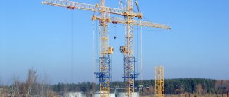
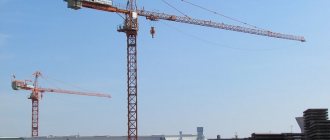
The KB-403 tower crane is a self-erecting lifting unit with electrical control, capable of moving on wheel-rail tracks. Equipped with a movable beam boom mounted on the same lattice tower and controlled by a system of ropes. Capable of lifting various loads to very high heights (up to the height of a 16-story building) with comparative compactness and coverage of a large work area.
Tower crane KB-403 - general information
KB-403 tower cranes are assembled at specialized construction equipment factories in different cities of the Russian Federation and throughout the CIS: Nyazepetrovsk Crane Building, Moscow Stroymash Production Association, Karacharovsky Mechanical, Podolsk, Tashkent Mechanical Experimental Plant, etc. Factory assembly involves delivery to the working location crane with a finished chassis and a set of other elements of the tower crane, the assembly and installation of which takes place on the construction site in the following sequence:
- Crane rail tracks are installed and leveled.
- The chassis is installed using a medium-duty truck crane.
- The tower is brought into a vertical position.
- The boom is hung on the support hinges.
- The tower is extended and all components are adjusted using its own tower-type mechanisms.
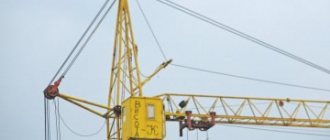
Photo of tower crane KB 403
IMPORTANT! The crane can be transported to a new construction site already assembled and quickly installed using a truck crane and its own mechanisms.
KBM-401
| KBM-401 | |
| KBM-401 cranes (with beam boom) | |
| Crane type | Tower: rail, 33 sp. |
| Boom type | Beam |
| Load moment | 100-200 • |
| Maximum load moment | 102-200 • (Spanish) |
| Reach, maximum (horizontal boom) | 20 /40 |
| Time for full departure change | n-d |
| Load lowering depth | 5 |
| Tower type | Growing from below, rotating |
| Maximum number of tower sections | 3-9 |
| Elevator lift | No |
| Wind operating area | I…VI |
| Electric motor power | 67 kW |
| KBM-401 | |
| Version with lifting boom | |
| Crane type | Tower: rail, 9 sp. |
| Boom type | Lifting |
| Load moment | 96 - 187.5 (Spanish) |
| Maximum load moment | 187,5 • |
| Reach, maximum (horizontal boom) | 20 -30 |
| Tower type | Growing from below, rotating |
| Maximum number of tower sections | 6-9 (Spanish) |
| Elevator lift | No |
| Wind operating area | I…III |
KBM-401P
— tower crane, self-propelled, rail-mounted, full-rotating, has 33 versions (from
“-00”
to
“-27”
and from
“-33”
to
“-39”
), designed for construction and installation work of residential and administrative buildings and structures with a mass of mounted elements up to 10, refers to modular type cranes[1]. To service a building from several sides, the crane (versions up to 160 •) can move along rails with curved sections, with a minimum radius of curvature of the internal rail of 10 [1].
general description
Executions are unified and can be obtained on the basis of the basic model (execution «-00»
) when the number of sections of the tower changes, the booms and have different load capacity, lifting height, load moment, boom reach, permissible wind speed [1]. The tower is built up from below with replaceable intermediate sections using its own mechanisms and an auxiliary crane. The main boom, depending on the design and model, is a beam type or a lifting, sectional, triangular section. A cargo trolley with a hook clip moves along the lower chords on the main beam type boom [1]. The crane is powered from an alternating current network 380 with a frequency of 50, with a transformer power of at least 70 • [1]. Manufacturer - RKZ [1], [2].
Design
Main elements of the crane:
- running trolley - is a two-wheeled trolley with one wheel drive. The design is similar to typical “unified crane trolleys”. All four bogies are driving[1].
- The running frame of KBM-401P
and
KBM-401PA
is a flat support frame with rotating weather vane beams[1]. - rotating platform - the design is described below.
- tower - is a type of “bottom-up” crane. It consists of a portal, intermediate sections, an upper section with a mechanism for lifting the cabin and a head. The sections are installed from below sequentially one after another[1].
- control cabin - installed on a retractable mechanism in the upper section of the crane. In later models - remote[1].
- rotary device KBM-401
- consists of two turntables[1]. - boom—represents a sectional truss. The beam can be installed horizontally or at an angle of up to 30 degrees. Lifting - up to 65 [1].
- load trolley - A load trolley with a hook clip moves along the lower tiers of the main boom. Cargo trolleys are used in two types (depending on the design)[1].
- hook cage - is a biaxial suspension (similar to cranes KB-405
,
KB-407
)[1]. - portal - design and purpose are described below.
The characteristics of the crane are given in the card[1].
Crane assembly
Before installation, all pins and holes, supporting planes of all structures must be cleaned and lubricated with a special lubricant. Installation is carried out with one auxiliary crane on a truck or pneumatic wheels with a lifting capacity of at least 8. A sleeper cage[1] is required for installation. The general installation diagram below is suitable for tower cranes with both luffing and girder booms (different for the KBM-401-41
)[1].
Crane installation steps:
- Preparation of an installation site measuring 50 by 20, with a transverse slope from the building under construction - 0.008-0.01 and a longitudinal slope - 0.002-0.005[1].
- Equipment of the crane power point with electricity with a voltage of 380 and a frequency of 50 [1].
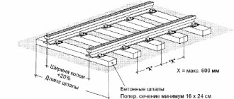
Figures 1 and 2 - Ring frame
- Crane tracks. The distance from the axis of the rail tracks to the most protruding part of the building under construction must be at least 4.7. The installation site must ensure that the distance between the crane metal structures and power lines is at least 30 [1]. Preparation, installation, leveling and grounding of tracks[1].
- Installation of the running frame and running trolleys: Mark the position of the running trolleys on the crane tracks[1].
- A sleeper cage is laid along the axis of the crane track (in Figure 1). A ring frame is installed on it (in Figure 2)[1].
- A running trolley is installed on the rail, then a lining is installed under its drive so that it does not tip over. A truck crane is used to lift the weather vane and lower it onto the pin of the undercarriage. The free end of the weather vane is inserted into the eyes of the annular frame until the holes coincide. Then the axle is inserted and secured with a bracket. The rest of the trolleys are installed in the same way and fastened to the weather vanes[1].
- Raise the ring frame and dismantle the sleeper cage. Then the frame is lowered onto the trolleys, and the stops are removed from the weather vanes and protective covers are put on[1].
- Installation of a rotating platform: A rotating platform with a rotating support-circle is installed and secured to the running frame, then the boom and cargo winches are installed on it[1].
- Electrical equipment panels (electrical cabinets) are installed, which are located in three options: in the control cabin; in two cabinets on opposite sides of the platform; in two cabinets - on one platform. The options depend on the name of the equipment used (type of control panels) and the methods of placement and installation. If cabinets are used, platforms are installed under them[1].
- Counterweight plates and a mounting strut are installed, connecting the eyelets of the rods and the strut earrings[1].
- Installation of the portal: Diagonal beams are installed on the lower frame of the portal. The gantry lugs are connected to the turntable brackets. Then the portal is lowered onto a sleeper cage laid under the lower frame of the portal[1].
- Install platforms, fences and stairs, tower struts, and upper sections[1].
- The locks on the portal are first removed by pulling the chain by the hooks on the belts of the portal. The upper section with the attached head is brought to the upper frame of the portal and inserted into the portal rollers, after which the section is pushed into the opening - into the lower tier of the rollers and brought to the cradle. The mounting studs are removed from the cradle, after which the flanges of the upper section are seated on the flanges of the cradle by longitudinal movement, and then the portal locks are lowered[1].
Boom installation
Depending on the design of the crane and the type of boom (lifting or girder boom), the assembly steps differ:
- Assembly and installation of a lifting boom
: using an auxiliary crane, sections of the boom are docked and fastened together. After this, a spacer with a strut and a rod is installed on the boom, then the boom is raised and its eyes are brought to the head brackets[1]. - Assembly and installation of the beam boom
: Place the root section on the stand, and roll the load trolley onto it. Next, the boom sections are joined and fastened together. Roller supports are installed on the beam of the head section. It is equipped with service platforms, then the boom is raised and its eyes are brought to the head brackets[1].
Tower extension
- By turning on the boom winch “to lower”, a slack is created in the boom rope, sufficient to extend the tower by one section. Set the gaps between the eccentric rollers and the belt pipes of the tower by turning the levers and fixing them in one of the holes on the bracket. Remove the studs securing the cradle to the diagonal beams, connect the flanges of the cradle with the lower flanges of the upper section of the tower [1].
- An auxiliary crane is used to lift the boom so that it does not touch the ground, then the tower is extended to a position where the lower tier of stops of the upper section with the cabin rises above the portal locks[1].
- The tower is placed with stops on the supporting planes of the locks[1].
- When extending the tower, the end of the boom, if there are no roller supports on it, is supported in weight by an auxiliary crane[1].
- Diagonal beams are unfastened and deployed to clear the opening: for the passage of tower sections inside the portal. Then the tower is placed with the upper tier of stops on the supporting planes of the locks and the upper section is uncoupled from the cradle[1].
- The stage of fastening the tower
[1].
Tower mount
- Using a cargo winch, the tower is first lifted until the lower tier of the stops of the lower section exits above the supporting plane of the locks, then lowered onto the locks. The diagonal beams are rotated around the axes inside the portal and secured, then the tower is raised to a position where the stops of the lower section are higher than the supporting plane of the locks. Next, the locks are overturned using chains. The tower is lowered using a cargo winch until it lands on the diagonal beams[1].
- After the tower is fully extended and attached to the portal, the guys are secured to the turntable and the eccentric rollers of the portal are moved away from the belts of the tower section[1].
- Raise the boom to the working position and push the cabin into the working position, connect the strut struts with the eyes and connect them with a safety cable to the tower belts[1].
- When installing a crane with a beam boom, turn on the boom winch and raise the boom to a horizontal position, install the load trolley close to the stops and attach the rod to the tower. Restoring of ropes is carried out automatically when the boom is moved from a horizontal position to an inclined position (at an angle of 30) and back[1].
- Install the equipment cabin, a stand under it, as well as an entrance platform. Perform electrical installation work[1].
- The anti-theft grips of the running trolleys are deployed. Configure and adjust safety devices and limit switches[1].
Building up
- Clamp the anti-theft grips, then depending on the type of boom:
- When the crane is designed with a beam jib, the load rope is transferred to a load trolley and the rod is undocked[1].
- When the crane is equipped with a lifting boom, the struts are disconnected from the boom heel eyes[1].
- The work is carried out in the following sequence:
- Remove the equipment cabin, platforms and stand under the cabin. Move the control cabin into the installation position, lower the boom to the vertical position [1].
- Remove the guy wires from the platform and the fastenings to the portal. The eccentric rollers of the portal are brought to the belts of the tower section[1].
- The flanges of the tower and cradle sections are disconnected from the diagonal beams and connected to each other. Using a cargo winch, they first lift the tower above the locks, then lower it onto the stops. Remove the fastenings of the diagonal beams to the portal, and then lift them and unfold them, freeing the passage for the sections[1].
- Undo the lower flanges of the tower section with the cradle, then lower the cradle until the stops on the turntable engage [1].
- Undocking the cradle from the mounted section[1].
- Before installing the intermediate sections of the tower on the cradle with an auxiliary crane, the boom is moved away from the tower using a truck crane and fixed on an inventory stand or using a guy rope[1].
- For various versions of the crane, depending on the height of the tower, a pair of guy wires of the appropriate length is installed, with a distance between the centers of the wedge cages. After the boom lifts off the ground, the roller supports are removed from it[1].
- The stage of fastening the tower
[1].
Modifications
KBM-401PA
Version with lifting boom
KBM-401PA
— a modular type tower crane on rails, with a luffing jib, with a lifting capacity of 10.
Has 9 versions ( “-28”
,
“-29”
,
“-30”, “-31”
,
“
-32
”
,
“-42”
,
“-43” , “-44”
,
-45”
), differing load altitude and wind characteristics.
In terms of design, the main components, except for the working boom and the reeving scheme for cargo ropes, are unified and coincide with the KBM-401P
with a beam boom[1].
Produced by the Rzhev Crane Manufacturing Plant, Rzhev [1], [2].
KBM-401HL
KBM-401HL
— a modular type tower crane, on rails.
Designed for operation in areas with cold climates at ambient temperatures from minus 60 to plus 40. The crane is equipped with a beam boom and a load lifting height of up to 47 with a maximum reach of a horizontal boom; with an inclined boom (at an angle of up to 30), the maximum lifting height can increase to 60. Has the “-UHL”
. Produced by the Ukhta Mechanical Plant, Ukhta[2].
KBM-401UHL
Crane KBM-401UHL
is a modernization of the
KBM-401HL
. It has 24 versions, differing in cargo height characteristics, and:
- KBM-401UHL-23
(version
“-23”
) is a mobile crane on rails. Lifting height up to 47.4. - KBM-401UHL-24
(version
“-24”
) is a stationary crane. Lifting height up to 53.
The models are produced by the Ukhta Mechanical Plant, Ukhta[2].
KBM-401P-41
KBM-401P-41
— tower crane-loader with a load moment of 200 •, having a modification with the index
“A”
(
“-PA-41”
). Designed for mechanization of lifting and transport operations in warehouses, landfills, bases, etc. The crane has a base of 6, and has a maximum lifting height of up to 13. The maximum lifting capacity of the crane is 8, with a maximum reach of up to 6.5. Produced by the Rzhev Crane Manufacturing Plant, Rzhev[2]. Counterweight weight - 55, structural weight - 50. Power 70 kW[1].
Transportation
- Transportation by rail. When transported by rail, the crane must be disassembled into separate enlarged units, the placement and fastening of which units on railway platforms and gondola cars must be carried out in accordance with. with drawings and fastening calculations approved in the prescribed manner. In this case, they are guided by the “Technical conditions for loading and securing cargo” of the Ministry of Railways[1].
- Transportation by water transport. They are guided by SNIP and the “Rules of safety precautions and industrial sanitation for loading and unloading operations in ports and piers” of the Ministry of River Fleet of Russia[1].
- Transportation of the crane by road. It can be carried out in separate units using standard vehicles, depending on local conditions, vehicle characteristics and traffic police requirements. In this case, they are guided by the “Road Rules” and installation instructions[1].
It is advisable to transport the crane from site to site over a distance of no more than 300 in a partially assembled form (without intermediate sections of the tower, boom and counterweight) on dolly trolleys with a specially equipped tractor unit, KRAZ-255V with a ball joint or another tractor with a performance rating not lower than KRAZ- 255V. Transport dimensions of the road train during transportation: length -27.8, height - 4.2, width: 4.02[1]. Intermediate sections of the tower, the head and sections of the boom, counterweight plates, tools, mounting devices and fasteners are transported separately by standard vehicles[1].
Scope of application
Cranes of the KB-403 type are particularly popular and the most widely used among other special lifting machines. They are used on large construction sites and facilities that require large volumes of construction or installation work, speed and high productivity:
- In the construction of residential or administrative buildings.
- On the construction of large industrial complexes.
INTERESTING! KB-403 is capable of performing absolutely all work on lifting any cargo on site, which allows significant savings on the use of additional lifting equipment.
Peculiarities
The KB-403 crane belongs to the IV size group (by load moment) of tower cranes, as indicated by the digital index 4 in the marking, and has a rotating tower (index 03). A sufficiently high load moment determines the special vehicle’s greater resistance to rollover and the high economic efficiency of its use.
Device
The convenience and productivity of the crane are also explained by its design features:
- The lattice structure of the tower and boom makes the structure lighter and provides greater precision of movement with a free view of the actions being performed.
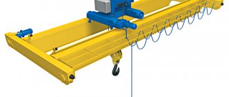
- The cargo trolley, movably secured by hinges and cables to the boom, provides both vertical and horizontal transport of building parts and materials.
- The rotating platform of the tower is made in the form of a roller circle.
- The tower consists of several retractable sections with a collapsible head section and the possibility of growing from below.
- The KB-403 rope system is equipped with a pulley system.
- The cabin is installed unified for high-rise cranes with a height of up to 20 or more than 20 meters.
- The beam boom also has a sectional design.
- The crane can be equipped with a safety device with a coordinate-type protection system.
- Control is carried out both from the crane cabin and from the ground.
- For comfortable work in winter, the cabin is equipped with a heating system.
Scheme of tower crane KB-403
Specifications
To install the crane, rails of type P43 or P50 are used.
It can withstand wind loads from degree I to IV and temperature range from -40 to +40 0C.
The remaining qualitative and quantitative technical characteristics of KB-403 are presented in the table:
| Parameter | Unit measurements | Magnitude |
| Control - electrical, input voltage | IN | 380 |
| Motor power | kW | 116-120 |
| Swivel power | kW | 5 |
| Free height | m | 37,9-54,7 |
| Width (on track) | m | 6 |
| Section database | m | 1,8 |
| Number of tower sections | PC | up to 5 |
| Turning part, radius | m | 3,8 |
| Total weight of the structure | T | 76,6-80,5 |
| Counterweight mass | T | 30 |
| Maximum lifting capacity (with minimum boom shot) | T | 8 |
| Load capacity at max. boom outreach | T | 3 |
| Maximum lifting height | m | 54,7 |
| Maximum boom reach | m | 30 |
| Load moment (maximum) | t*m | 120 |
| Boom radius (min/max) | m | 5,6/30 |
| Boom reach at max. lifting | m | 16,5 |
| Maximum movement speed | m/min | 18 |
| Full cart speed | m/min | 30 |
| maximum lifting speed of hook suspension | m/min | 55 |
| Smooth landing | m/min | 5 |
| Rotation frequency | rpm | 0,65 |
| Wheel load on rail | kN | 270 |
All tower cranes are assembled from separate sections of towers and booms, which makes it possible to create various designs and modifications from them, differing in reach, lifting height and load capacity. These qualities are especially evident in the so-called modular tower cranes, the development of which has begun in recent years.
Basic machines with a load moment from 100 to 400 tm are available in various designs, the number of which in some models reaches 41.
In modular cranes, it is possible to obtain a crane with a beam and a luffing jib for the same standard size. Cranes with a load moment of 100 and 250 tm, as a rule, are made with a rotating tower, and cranes with a moment of 250-1000 tm are made with a fixed tower.
Most of the manufactured tower cranes with a slewing tower are designed in the so-called mobile design, which ensures their relatively quick relocation. Attachment cranes, as well as mobile cranes with a large single lifting capacity and with a non-stop door tower, are transported disassembled into enlarged units.
Almost all valves are manufactured in a design designed for operation in areas with a temperate climate at an ambient temperature of ±40 °C. Only three models of cranes KB-100.ОАС, KB-100.ОА-1С and KB-309ХЛ are made in the HL design, allowing them to operate at temperatures down to -60 “С. The cranes are powered by electricity from an external general-purpose network with voltages of 220 and 380 V. Therefore, most cranes are equipped with AC electric motors, and only some of them have converting units in the form of thyristors and a motor-generator that allow powering the motors of the mechanisms with direct current.
In cranes with a lifting capacity of 5 and 8 tons, a single-speed cargo lifting winch is used for the construction of mainly 5-7-story buildings. Cranes with a lifting capacity of 10–25 tons and a high lifting height are equipped with multi-speed winches. The control cabin comes in two types: remote and built into the tower. To facilitate ascent and descent on high cranes, a lift for the driver (KB-674A, KB-504) is mounted.
The metal structures of towers and booms are made from angles or tubular elements.
The conditions for using tower cranes (by lifting height) in various windy areas are given in Table. 21.50.
Table 21.50 Conditions for using neck taps in various windy areas
A special group of tower cranes are KBR cranes, which, thanks to the special design of the jib assembly and its assembly system, are designed to work in cramped conditions, fit into narrow passages and pass under arches.
KBR-1 crane (Fig. 21.49, a) with a beam boom with a lifting capacity of 5 tons. The basic model has two versions, differing in reach of 20 and 30 m. The running gear is provided in the form of a rail-wheeled and trackless - on supports. The running frame is similar in design to the frame of the KB-308 crane and differs in the ability to replace the running trolleys with supports. Ballast slabs are suspended from the frame. The dimensions and layout of the turntable are made in the form of a separate block, transported on a rolling axle with wheels in a trailer to the KAZ-608 tractor unit. When assembling the crane (Fig. 21.49, b), the base of the boom is fixed to the boom carriage, which is moved along the tower. Sections of the tower are connected to the base using a special mounting device (crane-jib), which can be mounted on the tower. After assembling the boom, it and the carriage rise to the highest position and lower to the working horizontal position.
The KBR-2 crane is a modernized model of the KBR-1 crane. The load capacity was increased to 8 tons, and the lifting speed of the maximum load was reduced to 16 m/min, which made it possible to reduce the installed power of the machine.
Technical characteristics of KBR taps are given in table. 21.51.
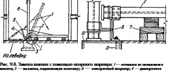
Rice. 21.49. Tower mobile crane KBR-I: a - general view; b - installation diagrams; 1 - ballast; 2 - counterweight; 3 — control cabin; 4 — mounting device; 5 - carriage; b - boom support section; 7 — mounting pulley; 8 — boom assembly; I - securing the boom section to the carriage; II - assembly of boom sections using a mounting device; III — extension of the assembled boom upward; IV - installation of the boom in the uppermost position; V—move the boom to a horizontal position; VI - installing the boom in working position
Table 21.51
Technical characteristics of tower cranes type KBR
Cranes KB-100.3 and KB-100.1A-1 have a lifting capacity of 8 tons with a luffing jib.
The rotating tower is made of a pipe with a lower counterweight on the platform. In a vertical position, the tower is held by struts and a rope system. The crane is equipped with a rotation limiter, which allows the tower to rotate in one direction no more than three turns.
The cranes are equipped with 2- and 4-fold reeving of the cargo pulley, which provides the highest lifting capacity of 5 and 8 tons, respectively.
They are equipped with standardized cargo and boom winches, a turning mechanism, undercarriages and a control cabin.
The cranes are transported assembled on a pneumatic trolley in tow to the tractor.
As a result of the latest modernization, the KB-100.3B crane was created, which has a composite tubular tower that can be extended through a lattice portal. This design allows you to obtain different versions of the lifting height.
Crane KB-100.3B (Fig. 21.50) with a lifting capacity of 8 tons with a lifting boom. It has six versions, differing in lifting height 33; 27.4 and 21.8 m, as well as the type of cargo winch. The first version of the winch is single-engine with a braking machine, the second is double-engine.
There are two more versions of the crane with a lifting capacity of Ute with lifting and girder booms resting on the portal with the ability to pass trains (Fig. 21.51, 21.52). The boom and supporting part of the crane are lattice, and the tower is tubular, which is extended through the portal part during installation. The cabin with the control panel is suspended under the top of the tower.
Rice. 21.50. Tower crane KB-Sh0,ZB (basic model): I, II, III – versions; 1 — running frame; 2 - counterweight; 3 - boom; 4 — control cabin; 5 — tower with a supporting portal; b - rotating platform
The crane is equipped with instruments and safety devices, the limit switches of which are of lever and spindle type. The load limiter of the ONK-M system is used.
The crane is equipped with a KTA-2-0.5E-01U1 air conditioner and an M-95M-2 anemometer. Electricity is supplied via a flexible cable wound onto a cable drum. Ascent to the cabin via a ladder located inside the tower.
Cranes KB-J 00.OA-1S and KB-100.OAS with a lifting capacity of 5 tons, with a lifting jib in the HL version, are designed to operate at temperatures from +40 to -60 °C. The cabin has increased thermal insulation and heating.
Rice. 21.51. Tower crane KB-100.ZB.03 with a portal and a luffing jib
Rice. 21.52. Tower crane KB-YuO.ZB.04 with portal and beam jib
The cabin is provided with natural supply and exhaust ventilation. Outside cold air (in winter) enters the air ducts under the floor and between the walls, heats up and then enters the cabin. The KB-309HL crane (Fig. 21.53) with a lifting capacity of 8 tons (with 4-fold reeving) is equipped with a lifting boom that provides lifting of loads weighing (with 2-fold reeving) 5 tons at a hook reach of 25 m.
The crane can operate in areas with cold climates at air temperatures from -60 to +40 °C. The cabin has increased thermal insulation, is equipped with special heating panels, and the electrical cabinets are equipped with heaters that maintain their internal temperature from +1 to 5 C. Operation of the crane is allowed in wind regions I-VI, and in the presence of obstacles more than 10 m high - in region VII.
Rice. 21.53. Tower crane KB-309HL and its load characteristics: 1 - with 2-fold reeving; 2 - with 4-fold reserve
The crane can operate on curved sections of track with driving trolleys placed on the outer rail. It is equipped with a cable reel, which must be disconnected in these areas.
The tap does not have a ring pantograph and therefore it can turn in one direction no more than 1.5 turns.
Installation and dismantling of the crane is carried out using its own mechanisms, using a truck crane with a lifting capacity of 10 tons. The crane is transported assembled (without counterweight and ballast) on movable pneumatic wheels in a trailer attached to a tractor-trailer, forming a road train with a length of 27 m, a height of 4.2 and a width of 3 ,74 m. The load from the wheel on the rail is 230 kN, which allows the use of the P 50 rail.
The working area of the crane and its structure are illuminated by floodlights (3 pcs.) and lamps mounted on it. It has an hour meter that records how long it has been running.
KB-308A crane (Fig. 21.54) with a lifting capacity of 8 tons with a beam boom, which can be installed at an angle of 30°, providing a lifting height of up to 42 m. With an inclined boom, the lifting capacity is 5 tons. The crane, in addition to the basic one, has 2 height versions by changing the number of tower sections: with 4 sections - 32 m; at 3-26.4 m and at 2-20.8 m. The basic machine and the first version have a load capacity at the maximum reach of 25 m - 4 tons, and the second version - 5 tons. By changing the mass of the counterweight on the chassis for each version, you can change wind areas where the crane operates.
Basic machine, ballast 18 tons—I—IV region; 1st version, ballast 17t - V region; ballast 9 t - I-IV region; 2nd version, ballast 18 tons - VI region, ballast 9 tons - I-V region.
Crane operating mode group - 4K. The cargo winch is twin-engine, providing a 2- and 3-fold increase in the speed of lifting loads. The running gears are installed on two trolleys located on two rails. The tension of the cargo rope can be done automatically when, simultaneously with lifting the load, the boom winch is turned on to lower the boom. An adjustable cabin can be installed on each section of the tower and above the portal. The canopy cabin is moved using a cargo rope through a block attached to the rail.
The crane is installed by self-lifting the tower and boom from the transport position. The tower is grown in sections through a portal.
Crane KB-401B (Fig. 21.55) with a lifting capacity of 8 tons with a lifting boom. A multi-speed winch is mounted on it, providing different lifting speeds depending on the load capacity. The crane is designed to work in windy areas I-VII by changing the height; boom suspension from 43.6 to 26.8 m. A rope with a diameter of 24 mm is used on the winches.
Crane KB-402V (Fig. 21.56) with lifting capacity; 8 t is equipped with a lifting boom on which a jib can be mounted. The load capacity on the jib is 3 tons. The winches also use a rope with a diameter of 24 mm. Electric motors with a different rotor are installed on the load lifting and turning mechanisms, and short-circuit motors are installed in the boom winch and the crane movement mechanism. A controlled normally closed brake is installed on the turning mechanism. When working with a jib, the speed of lifting and lowering the load is 2 times higher. The crane can move with a load on a hook along a curved section of a rail track with a radius of 7 m. It can work in wind regions I-III.
Cranes KB-403B, KB-403A (Fig. 21.57) with a lifting capacity of 8 tons with a beam boom.
It has replaceable boom sections, which allows it to be extended to 20, 25 and 30 m and towers with a height of 18.6 to 41 m. The crane can operate in wind regions I and V at wind speeds up to 13 m/s and in IV, V - at speeds up to 17 m/s. It can move when rounding a path with a radius of 7-10 m. The ringless pantograph limits the angle of rotation to 120° in each direction. The assembled crane is transported by a road train with a length of 27.7, a width of 4 and a height of 4.2 m using a KrAZ-250 vehicle and 4 pneumatic wheels with 14.0 x 20 tires.
Rice. 21.54. Tower crane KB-308A
The crane boom can be installed in three positions: horizontally, at an angle of 30 and 50°. The load trolley can be moved along inclined booms with the hook moving horizontally.
Cranes KB-405-1A and KB-405-2A (Fig. 21.58) with a lifting capacity of 10 and 9 tons with lifting booms. The greatest lifting capacity is provided at a hook reach of 13-18 m.
The cranes are designed to operate in wind regions I–III. Power supply of cranes with electricity from an external network; power source power of at least 100 kV • A. The electric drive of the cargo winch provides a 1.5-fold increase in speeds when lifting and lowering the hook and loads not exceeding 0.3 of the nominal (up to 2.5 tons).
The cranes can move along curved sections of the track with a radius of 7 m. In the cabin they
Rice. 21.55. Tower mobile crane KB-401B: 1 - rotating platform; 2 - running trolley; 3 - counterweight; 4 — jib pulley; 5 - jib rope; 6 — hook suspension; 7 - boom; 8 — control cabin; 9— tower; 10—rotation mechanism; 11 — cargo winch; 12 - weather vane of the running frame; there is an air conditioner KA2-0.5E or KTA-2-0.5E-0GA.
The cranes are mounted and dismantled using their own mechanisms and a truck crane with a lifting capacity of 16 tons. They are transported assembled by one road train with a length of 29, a width of 4.02 and a height of 4.2 m. The tractor is a KrAZ-250 vehicle.
Technical characteristics of tower cranes of the 3rd and 4th size groups are given in table. 21.52 and 21.53.
Tower modular cranes. These KBM series cranes are a special group. They are designed from unified module elements: tower and boom sections, mechanisms, control cabins, electrical cabinets, slewing bearings, counterweight blocks, rope-block systems.
There are 4 basic models of KBM cranes for load moments of 100, 160, 250 and 400 tm and a lifting capacity from 8 to 25 tons. Each basic model has versions.
Modular cranes provide: increased speeds, hydraulic installation, beam booms, and operator lifts. They reduce the need for spare parts, simplify building installation technology, increase productivity and reduce operating costs.
The KBM-40Sh crane (Fig. 21.59, a, 6) with a lifting capacity of 10 tons is a model of a modular tower crane. In addition to the basic model in the crane, using replaceable tower and boom modules, you can get 32 versions, including 27 with a beam and 5 with a lifting boom, including 12 versions (assemblies) of the tower. For each design, you can have one of three types of cargo winch drive: multi-speed AC, AC switchable gearbox and DC. The last two drives provide high speeds for lifting loads weighing up to 2.5 tons and lifting and lowering the hook.
The cabin with electrical equipment in the form of a separate unit is located on the platform.
Replaceable tower modules with a length of 5.6 m and strs-ly 5 m each allow you to obtain a lifting height at maximum reach from 24.8 m to 58.4 and reach of 20, 25, 30, 35 and 40 m. With a lifting boom, the maximum height is 74 m.
The beam boom can be installed at an angle of 30°, which further increases the height! lifting capacity of 8.1 m. A cargo trolley with a load moving horizontally can move along an inclined boom.
Rice. 21.56. Tower mobile crane KB-402V: a - with a luffing jib; b - with an articulated boom
As part of each group of executions, the construction of a building with a height from 6-7 to 16-17 floors is ensured.
The crane can be used in various wind regions from VII to I.
The versions of the crane with a beam boom are combined into 4 groups: 20 m (7 versions); 25 m (6 versions); 30 m (7 versions) and 35 m (7 versions).
The depth of lowering the hook for versions 01...07 is 32-20 m; 00.08… 13.29-35 m; 14…20,30, 31-30m;21…27-35m.
Installation and dismantling is carried out using a cargo winch and an assembly pulley. The tower is assembled using the method of growing through the tower portal using its own winch and mounting pulley.
Rice. 21.57. Tower mobile crane KB-403B
The crane is transported in enlarged units (with the counterweight removed) by a tractor unit on a trolley with 8 pneumatic wheels. The length of the road train is 28, height is 4.2, width is 4.02 m.
The KBM-671 crane has a lifting capacity of 25 tons. The main parameters of the crane are adopted for 2- and 4-fold reeving of the cargo rope. It has a rotating head with a spring console and a beam boom. Designed to work in wind regions I–IV.
It is possible to move the counterweight along the console. The cargo winch drive uses direct current, and the other mechanisms use alternating current.
There is a lift for lifting the driver into the cabin, located inside the tower.
Table 21.52
Technical characteristics of tower cranes of the 3rd size group
Climbing can also be done using vertical ladders.
Installation and dismantling of the crane is carried out using a mounting clip and an additional jib crane. The crane is transported disassembled into enlarged units.
Technical characteristics of modular tower cranes are given in table. 21.54—21.55.
The KB-503B crane (Fig. 21.60) with a lifting capacity of 12.5 tons with a beam boom has three versions along the boom length of 35, 40 and 45 m. In addition to the horizontal position, the boom can be installed at an angle of 30° and a trolley with a load moves along it. Three turning mechanisms, a unified cargo and installation winch, and a main engine drive (generator - DC motor) are mounted on the platform. The cabin is located in the upper section of the tower and can occupy two positions: extended when the crane is operating and retracted in the transport position. To raise the tower there is a mounting winch on a rotating platform.
Transportation. The crane is transported assembled on dolly trolleys in tow to a KrAZ-255B tractor or in units on general purpose vehicles.
The KB-504 crane (Fig. 21.61) with a lifting capacity of Yute beam boom has three versions with an outreach of 35, 40 and 45 m. The greatest lifting capacity is provided at outreaches of 28, 25 and 20 m, respectively. The boom can be installed at an angle of 30° and moves along it cargo trolley while maintaining horizontal movement of the load.
The crane tower is sectional, which allows, as the height of the building under construction increases, to change its height by growing from below.
The crane is equipped with a lift for the driver.
The load and installation brace ropes are 24 mm in diameter, the rest are 37 mm in diameter, which simplifies the operation of the crane.
The load winch is driven by a DC generator. The turning mechanism provides the possibility of smooth braking and acceleration due to the alternate application and release of two brake pads.
The running gear of the crane consists of four three-wheeled trolleys. The trolleys are leading and balanced.
The crane is equipped with a tower extension limiter and an anemometer. It is mounted and dismantled using its own mechanisms and a jib crane with a lifting capacity of 16-40 tons.
It is transported assembled on five four-wheeled trolleys in tow to a MAZ-537 or KrAZ-255B tractor.
Crane KB-408 (Fig. 21.62) with a lifting capacity of Yuta beam boom. It has 13 versions, differing in reach (20, 25 and 30 m), lifting height and load capacity. The boom can be installed at an angle of 30 and 43°. The crane can be used in windy areas 1-7.
The maximum depth of lowering the hook is 30 m.
There are three types of cargo winch drive: direct current, alternating current with two electric motors and alternating current with a brake machine, which allows you to obtain the speed of lifting and lowering the load and hook suspension within a wide range.
The remote cabin is equipped with a KTA2-0.5E-01 air conditioner. The crane is equipped with a radio station and an M-95M-Ts anemometer.
The crane is transported in enlarged units on a rolling pneumatic trolley.
Rice. 21.59. Modular tower crane KBM-401P and its load characteristics: a - with a beam boom; b - with a lifting boom 01...32 - versions
Mobile cranes are distinguished by long reach of up to 50-66 m and lifting height of up to 71-83 m.
The cranes have standardized towers, booms, mounting posts, and mechanisms. Equipped with lifts for the driver inside the tower.
The running frame is supported by four double drive bogies. By means of replaceable sections of towers 6 m long, you can get 13 designs in the KB-674A crane, and 3 designs in the KB-676 crane.
The control cabin and equipment cabin are mounted on the rotating frame of the tower.
The design of cargo trolleys is designed for a load capacity of 12.5 and 25 tons with the number of cargo blocks 2 and 3.
The counterweight console contains two counterweighted trolleys, moved by a separate winch, and a cargo winch. At the end of the console there is a device for lowering and raising the cargo winch during its repair.
The tower is extended using a mounting stand with 2 winches for lifting the stand itself and for lifting the tower sections. The ropes are stored in pulleys on the mounting rack.
When building up the KB-676 crane tower, frames are fixed between sections, to which wall supports are connected when a certain height is reached. In the crane at a height of 49, 72.8 and 97 m, 1, 2 and 3 wall supports are installed, respectively.
In the basic crane KB-674A and its versions KB-674A-1... 10 control is carried out using command controllers located in the cabin; crane versions KB-674A-0...10-1 have an additional remote control - radio program RPU-2. The thyristor drive of the cargo winch and DC electric motors of the turning mechanism and the cargo trolley provide a wide range of changes in operating speeds, smooth acceleration, braking and landing speed of cargo.
Crane KB-674A-13 with a lifting capacity of 12.5 tons with a fixed tower and a beam boom. The mechanisms and components of the crane are unified with the KB-674A crane.
The height of the tower was reduced compared to the base crane, which made it possible to increase the reach to 50 m while maintaining a load moment of 400 tm. The cargo winch is equipped with a reversible thyristor DC drive, providing smooth acceleration and braking.
The design of the crane allows you to extend the tower by changing the length of the boom and use it to construct not only the underground, but also the above-ground part of the building.
The KB-676A crane with a lifting capacity of 25 tons is a modernized model of the KB-676 and KB-674A cranes. The lifting speed for loads weighing up to 9 tons is 35 m/min, and for large ones - 17.5 m/min. The following are used: an electric drive for winding up the tower sections, an equipment cabin instead of electrical cabinets, a reinforced running frame, a simplified installation diagram for the boom guys.
When not in operation, the cargo trolley is installed at the outreach, which depends on the design of the crane.
The KBSM-200-16 crane (Fig. 21.64) is mobile with a beam boom with a lifting capacity of 10 tons. The crane has a special feature - a boom assembly moving along the tower, thanks to which the boom together with the suspended cabin can be installed through each section, i.e. at the level of the floor being built and the best working conditions are created for the driver. The tower is mounted to its full height and guide blocks for the lifting tackle are installed on the upper section. The cargo winch and the winch for moving the cargo trolley are located on the counterweight console. The electric motors are powered using a flexible cable wound around a drum.
Rice. 21.62. Tower mobile crane KB-408 and its load characteristics:
Rice. 21.63. Tower mobile crane KB-674A: 1 - ballast; 2 — struts; 3 — mounting mast; 4 - movable counterweight; 5 — control cabin; 6 — boom rods; 7— hook suspension; 8—cable drum; 9 - running trolleys
MSK-250 crane with a beam boom with a lifting capacity of 16 tons. The tower is rotating, telescopic. The cabin is located in the upper section of the tower. The crane can only operate on straight rail tracks.
The most powerful of the MSK series of cranes is the MSK-400 crane. It has a lifting capacity of 20 tons at a reach of 20 m. The boom is a beam type, which can be installed at an angle and increase the lifting height from 52 to 62 m. In addition to the counterweight, the crane is equipped with reinforced concrete ballast. The parameters of this crane allow the installation of buildings and large block rooms weighing up to 18 tons.
The MKRS-300 crane has two versions: the MKRM-ZOOB tower crane with a lifting capacity of 25 tons and the MKRS-300P loader crane. The crane is equipped with a beam boom, which, due to replaceable sections of 5 m each, provides a reach from 20 to 35 m. The boom can be installed at an angle and the load trolley moves along the inclined boom.
The tower is also sectional, with one section 6.8 m long and the rest 5 m long.
Installation or removal of tower sections allows you to obtain a lifting height from 9 to 36 m, for a loader 15 m.
The tower rests on a rotating platform with a rear clearance of 6 m. The load chain hoist has a multiplicity of 2, and on a boom of 17.6 m and a load capacity of 25 tons - 4. A counterweight made of reinforced concrete slabs can change the mass from 30.6 to 49.8 tons.
The crane is transported in larger units on movable steerable trolleys.
Crane BK-1000B with a luffing jib, lifting capacity of the main lift is 63 tons, auxiliary on the Yut jib. This crane is the most powerful domestic tower crane. The cargo pulley has: with a load capacity of 63 tons, six branches, and with 30 tons - four. Changing the multiplicity of the pulley is achieved without re-passing the rope. The crane tower is rotatable and rests on a three-legged portal with ballast slabs placed on its legs. Its mass can vary from 21 to 102 tons, increasing with increasing lift height. In this case, the basic machine can be used in wind regions I-III, and the crane version can be used in regions IV-VI with a lifting height of 40.3; 29.7 and 23 m.
The cabin is located above the portal, and winches and a turning mechanism are also mounted there. The main lift winch has two drums and two electric motors. Thanks to the planetary gearbox with differential and different engine activation, it is possible to obtain several operating speeds for lifting and landing.
The crane is mounted using the method of sequential assembly of enlarged components and assemblies.
Since when operating cranes there is often a need to change machine parameters, several modernized types of cranes have been manufactured using the basic model of the BK-1000 crane.
The BK-YOOA crane uses a jib length of Yum instead of 3 m with a lifting capacity of 9 tons and the upper section of the boom is reinforced.
In the BK-1000B crane, the lifting capacity of the main and auxiliary hooks has been increased to 63 and 18 tons, respectively.
In the BK-1000-60 crane, by reducing the lifting height to 62 m and the boom length to 30.8 m, the lifting capacity is increased to 60 tons.
In the BK-1000-48 crane, the lifting capacity of the main lift is 48 tons, the height of the tower and the length of the boom are reduced, and no auxiliary lift is provided. The change in parameters was made for a specific object to be reconstructed in cramped conditions.
The two modernized cranes BK-1000D and BK-1000V have increased their lifting capacity to 80 and 100 tons. The booms have been shortened to 30.7 and 24.78 m, the auxiliary lifting mechanism has been removed, additional blocks and a new reeving of cargo ropes have been introduced.
A separate group of tower cranes consists of cranes for hydraulic engineering of the KBGS series with load moments of 450-1200 tm (Table 21.63). They have reduced lifting speeds, as well as a smooth landing of 1.25 m/min. what is required for supplying concrete mixture in buckets and installing reinforced frames.
Modifications
At the moment, there are several modifications of the basic model of the KB-403 tower crane, these are:
- The KB-403A crane, which is distinguished by lifting up to the 16th floor, more convenient and easier control from a structurally improved cabin, increased lifting speeds and movement of the loading trolley, as well as greater stability with an increased load moment.
- KB-403B, designed for lifting loads on buildings up to 17 floors. It has a larger boom radius and is available in 4 variants with different load torque (from 120 to 132), total height, boom radius, etc. It is distinguished by its reliable design and ease of maintenance.
- KB-403B.4 is used in lifting loads up to 35.4 m. It has an increased boom reach and load moment.
Comparative characteristics of the models:
| Options | KB-403A | KB-403B | KB-403B.4 |
| Structural weight, t | 50 | 50,5 | 46,6 |
| Total weight, t | 80 | 80,5 | |
| Track, m | 6 | 6 | |
| Load moment, t*m | 132 | 120 | 132 |
| Maximum load capacity, t | 8 | 8 | 8 |
| Load lifting at full boom reach, t | 4,5 | 3 | 3 |
| Maximum boom radius, m | 25 | 30 | 30 |
| Boom radius with max. load, m | 16,5 | 15 | 16,5 |
| Lifting height at full reach, m 41 | 41 | 41 | 24,2 |
| Maximum lift, m | 52 | 54,7 | 37,9 |
| Landing speed, m/min | 4,8 | 5 | 5 |
| Lifting speed max. load, m/min | 40 | 40 | 40 |
| Maximum lifting speed, m/min | 58 | 55 | 55 |
| The highest speed of the chassis | 18 | 18 | 18 |
| Speed of movement of a filled cart | 23 | 30 | 30 |
| Rotation speed, rpm | 0,6 | 0,65 | 0,65 |
| Possible degree of wind gust | IV | III | VII |
The video shows the installation process of the KB-403 tower crane:
KB-402
Cranes series KB-160
and
KB-402
have a base of 6. The crane boom, as well as all supporting structures, are made of metal pipes in the form of a lattice structure and are connected to each other using flange connections.[3]. Structurally they consist of:
Turntable and turning mechanism
Made in the form of a flat design. A portal is installed on the platform. In the front part at the top there are the eyes of the support joint. On the side there are cabinets with electrical equipment of the crane (command controllers, starters, etc.). At the rear, rods are welded to the transverse beam for attaching the lower frame of the jib pulley. When installing the crane, the main ballast slabs (30) are placed on the transverse beam. Braces and posts are attached to the longitudinal beams, which together form a two-legged post. Working struts are hinged to this rack and serve to hold the tower in a vertical position. The platform also contains the main mechanisms of the crane - the rotation mechanism, cargo and jib winches. Two counterweight blocks are attached to the sides with steel traction pins. The platform rests on a running frame with rotating supports (has an X-shape in the working position) and is connected to it using a rotating mechanism called a slewing support (abbr. OPU). Rotating mechanism on the basic model of the KB-160
looks like a roller circle (in two rows).[3]
In later cranes, the design of the rotating mechanism was changed - on the KB-402
and
KB-403
it looks like a roller circle (in one row) with a diameter of 2500 [3].
Running frame with rotating vanes
Four rotary weather vane supports with fastenings for crane trolleys are attached to the running frame. The rotary vane supports are fixed in two positions - working and transport (working - fastening to the support trolleys, transport - fastening to the support base). KB-160
rests on four two-wheeled support trolleys (unified trolleys for cranes with a load moment of up to 200 • are used), two of which are driving, as they have an electric drive. For the crane, rails of the P-43 or P-50 type are used. Both straight and curved rails can be used. The main differences are in the location of the driving bogies (for straight rails, it is one-sided; in the second case, the driving bogies are placed on the outer rail relative to the center of curvature).[3]
Portal
The crane portal has a 4-sided design, which is open at the top and bottom for the passage of tower sections. On the rotating platform, the portal is mounted on a truss truss and held using special struts with a telescopic design.[3]
Tower
The crane tower is rotating, growable from below, of variable height (depending on the number of installed inventory sections). Contains the top of the tower (head), head section, additional (inventory) sections, spacers with blocks. On it there is a control cabin (on the right along the crane axis), fastenings for the lifting boom (in front). In the working position, the tower is secured in the lower tier by diagonal beams.
Tower KB-402
differs in the number of inventory intermediate sections, the number of which in this model is increased to 7, the length of the pulley ropes, as well as the design of the head section (it is collapsible and two-section)[3].
Control cabin
The control cabin is hung on brackets located on the head section of the tower (near the lifting boom hinge). On the KB-160
a unified cabin for low cranes
is installed (installation at a height of up to 20).
On the KB-401
and
KB-402
, a unified cabin for high cranes
is installed (installation at a height of over 20). The mounting methods are similar to those of the cabins. It differs from the base model cabin in a more advanced design, adapted for convenient viewing at a greater height of the crane, and also differs in internal content and equipment. Additionally, it can be equipped with air conditioning.[3]
Lifting boom
The boom is made of three parts (sections). Refers to inclined arrows. Attached to the head section of the tower. The reach changes by changing the angle of inclination to the horizon. At its end there are mounted a special hook lift limiter (the so-called OVP), cargo winches (blocks) and boom brace attachments, which serve to hold it. The beam is stored 2 times through the lifting boom, then proceeds according to the scheme: head blocks, spacer and through a balancing block installed on the boom winch located on the upper frame.[3]
Design of the main boom of the KB-402
almost identical
to KB-160
. It is distinguished by the presence of additional fasteners and the ability to install on them (on hinges) an additional metal structure - a jib 5.6 in length, which allows you to increase the lifting height of the crane (up to 66.5), but at the same time the load capacity is significantly reduced (from 8 to 2-3)[3 ].
Hook clip
Hook clip. It is a biaxial suspension: two cheeks, two axles, on which blocks, traverses and a hook are mounted on ball bearings.[3]. In KB-402
and
KB-403
, unlike
KB-160
, there are additionally metal external protective casings for hook cage blocks[4].