KamAZ is a powerful vehicle, but for its maximum efficiency and operational safety, it is necessary that all components and assemblies are in good working order, and that the components have sufficient service life. Correct adjustment of the power unit valves also contributes to this: it is important that the gaps are within the values established by the standards.
The correct clearances in the valve drive of the KamAZ engine ensure their reliable connection with the seats when the rod lengthens due to heating when the cylinder head settles when the chamfers wear out. If the clearances are broken, a knock appears in the engine, and over time it may even fail.
Let's look at how to adjust the valves on a KamAZ so that the further operation of the vehicle is as productive and long-lasting as possible.
ADJUSTING THERMAL CLEARANCES OF THE KAMAZ-740 ENGINE
First method
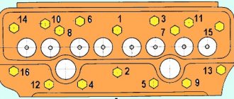
Adjust the following valves: ch 1. and issue; 2 issue; ch 3; 4 issues; 5 issue; ch 7; 8 VP. Adjust the clearances of the remaining valves after turning the crankshaft 360.
Second way
Adjust vp. and vol. valves of cylinder 1, and adjust the valves of the remaining cylinders in the order of their operation (1-5-4-2-6-3-7-8), turning the crankshaft by 90 each time when moving from cylinder to cylinder.
4. Make the adjustment by rotating the adjusting screw, having first loosened the lock nut so that the 0.25 mm probe passes freely, and the 0.3 mm probe passes with little effort. After adjustment, fix the locknut (Figure 2).
5. Replace the rocker arm covers, tighten their fastening nuts evenly with a torque of 5-6 N.m (0.5-0.6 kgf-m).
6. Reinstall the spark plug of the first cylinder.
7. Start the engine and listen to its operation (when the engine is running, in some modes you can hear a subtle knocking of the valves; there should be no “sneezing” in the carburetor or “shots” in the muffler).
ADJUSTING THERMAL CLEARANCES OF THE KAMAZ-740 ENGINE
Purpose of adjustment:
Bring the gaps to the value established by the technical specifications.
Specifications:
1. The engine must be cold (+15-20 C) or not earlier than 30 minutes after stopping it.
2. Fuel supply is turned off.
3. The cylinder head mounting bolts are tightened to a torque of 190-210N-M
4. Nuts securing the rocker arms are tightened with a torque of 44-56N-M
5. The gap size for intake valves is 0.25-0.30 mm, for exhaust valves 0.35-0.40 mm.
Adjustment procedure:
- Thermal clearances are adjusted simultaneously in two cylinders, following the operating order one after the other (1-5-4-2-6-3-7-8), during the compression strokes or power strokes in these cylinders. The valves of the adjustable cylinders must be closed at this moment. To adjust the gaps, the crankshaft is installed sequentially in certain positions: 1,2,3,4.
2. Remove the cylinder head covers.
3. Check the tightness of the cylinder head bolts.
4. Set the lock on the flywheel housing to the lower position (Figure 56).
5. Remove the hatch cover at the bottom of the clutch housing.
6. Set the crankshaft to position 1, for which: by inserting a crowbar into the holes of the flywheel bosses, turn the crankshaft until the latch engages with the flywheel.
7. Check the position of the marks (Figure 6) on the end of the fuel injection advance clutch housing and the flange of the drive coupling half of the high-pressure fuel pump drive. If the marks are at the bottom, disengage the latch from the flywheel, turn the crankshaft one revolution, and the latch should engage with the flywheel.
8. Set the lock to the upper position (Figure 5a).
9. Rotate the crankshaft in the direction of rotation (counterclockwise looking from the flywheel side) through an angle of 60V (rotation of the flywheel by the angular distance between two adjacent holes in the bosses corresponds to a rotation of the crankshaft by 30). The crankshaft is set to position 1. In this case, the valves of cylinders 1 and 5 must be closed (the rods can be easily turned by hand).
10. Tighten the nuts securing the rocker arm axle stands. Use a feeler gauge to check the gap between the toes of the rocker arms and the ends of the valves of cylinders 1 and 5 (a feeler gauge of 0.25 mm for intake valves and 0.35 mm for exhaust valves should pass freely, and 0.30 mm for exhaust and 0.40 mm for exhaust valves should pass with little force ). (The front valves for cylinders 1,2,3,4 are inlet, for cylinders 5,6,7.8 - exhaust).
11. If necessary, adjust the gap with the adjusting screw, having first loosened the lock nut, after adjustment, tighten the lock nut with a torque of 44-56 Nm (4.4-5.6 kts-m) and check the gap again.
12. Adjust the clearances in the valve mechanism in pairs sequentially in cylinders 4 and 2 (position 2), 6 and 3 (position 3). 7 and 8 (position 4). turning the crankshaft 180°' each time during rotation.
13. Start the engine and check its operation (with correctly adjusted clearances on a warm engine, there should be no knocking in the valve mechanism).
14. Reinstall the clutch housing hatch covers and cylinder heads, tightening them to a torque of 20-26 Nm (2.0-2.6 kgf-m).
Features of settings for various modifications
The procedure for adjusting valves on KamAZ may vary depending on the installed engine modification.
In order to do everything correctly, it is recommended that you read the “Valve Clearance Adjustment Procedure” section in the owner's manual.
Euro 1
In order to adjust the clearance on a Cummins engine that has 6 cylinders, you need to do the following:
- Remove the locking mechanism from the connection with the flywheel and rotate the crankshaft 360°. The valves of the cylindrical device should open.
- Check the tension of the fastening screws of the rocker arms of the adjusting cylindrical elements.
- Using a special device, check the distance between the base of the rocker arms and their ends.
- If the limit exceeds 42-52 Nm, then valve adjustment will be required.
- Loosen the lock nut of the reduction mechanism.
- Insert the measuring device into the resulting gap.
- Rotate the screw using a screwdriver to set the required distance.
- Adjust the valves in cylindrical parts numbered 4, 2, 6, 3, turning the crankshaft half a turn each time.
Euro 2
To adjust the valve elements on equipment with a Kamens engine, manufactured according to the international standard Euro-2, you need:
- Remove the covers from the cylindrical device.
- Check the tightening level of the mounting bolts.
- Set the flywheel locking part to the lower position.
- In two steps, remove the cover from the clutch mechanism and injection pump.
- Turn the crankshaft.
- Using a special wrench, check the tightening torque of the rocker arm mounting screws.
- Loosen the tension on the lock nut.
- Insert the feeler gauge into the gap and set the gap to 0.4 mm.
- Hold the screw with a screwdriver, tighten the nut and check the amount of the set gap.
- Rotate the crankshaft 60° from top dead center.
Euro-3
Instructions for adjusting valve elements on a vehicle with a Cummins engine (Euro-3):
- Remove the cap and cover from the heads of the cylindrical mechanism.
- Remove the rocker arm axle and struts.
- Move the crankshaft until it closes the valve elements in cylinder number 1. After this, you can begin adjustments in the fourth, sixth, seventh and eighth cylinders.
- Move the crankshaft again and adjust cylinders 2, 3 and 5.
- Using a torque wrench, check the tension level of all cylinder head fasteners in the cylinder firing sequence. If necessary, tighten the elements (up to 10 Nm).
- Return the rocker arm axle to its place, adjust the gap between the valve parts and the rocker arm arrangement.
Euro 4
Adjusting the valves of the Kamenets engine, manufactured according to the international environmental standard Euro-4:
- Remove all protective elements from the cylindrical mechanism.
- Set the flywheel locking device to the lower position.
- Remove the hatch cover, which is located at the base of the clutch mechanism.
- Using a small crowbar inserted into the flywheel connector, rotate the crankshaft 1.5 turns.
- During each movement of the crankshaft, the valve elements of the cylinders must be adjusted.
Adjusting KAMAZ valves
Adjusting valves on a KAMAZ vehicle is always difficult. This is due to the fact that it is very difficult to navigate the position of the pistons and set each piston separately to top dead center (TDC) at the moment of fuel compression in the combustion chamber. And to make adjustments, you need to know a certain sequence of actions.
It is advisable to carry out the adjustment together with a partner, since it is necessary to rotate the crankshaft from below the car and it is advisable to use an inspection hole. There is a special window in the flywheel housing, and holes on the flywheel itself. If a rod of the appropriate diameter is inserted into these holes through the viewing window, then with its help the flywheel can easily rotate the length of the technological window, when the rod rests on one side of the window, another hole will appear on the other, and by moving the rod into it we can continue rotating the flywheel. The flywheel must be rotated in the direction of rotation of the crankshaft, as it rotates when the engine is running. There is a stopper on the top of the flywheel housing. And there is a recess on the flywheel; when the stopper enters this recess, the flywheel will take a position corresponding to the position of the piston of the first cylinder at TDC.
But we need to bring the piston to TDC at the moment of fuel compression in the first cylinder. Therefore, we focus on the mark located on the high-pressure fuel pump (HPF). As soon as the mark on the fuel injection pump is set at the time of fuel injection in the first cylinder, only then does the locked flywheel assume the correct position.
Now we remove the stopper and rotate the crankshaft through two holes in the flywheel, which corresponds to a rotation angle of 60 degrees; in this position, the valves of cylinders 1 and 5 are completely closed.
You constantly get confused in the direction of rotation of the crankshaft. To test yourself there is a simple way, stand in front of the cabin, and imagine that you are starting the engine from the handle clockwise, in this direction the flywheel should rotate, that is, if you rotate the flywheel from below using a rod, the rod will move towards the batteries . So, we adjust the valves of cylinders 1 and 5. Then we rotate the flywheel through 6 holes, which corresponds to 180 degrees of rotation, and adjust the valves of cylinders 4 and 2. We turn 6 more holes and adjust the valves of cylinders 6 and 3. And for the last time we turn it by 6 holes and adjust the valves of cylinders 7 and 8.
The adjustment of the valves itself does not cause much difficulty; it is necessary to establish the permissible gap between the valve stem and the rocker arm, this is done using an adjusting screw locked with a nut. Unscrew the lock nut, loosening the adjusting screw, and install the feeler gauge between the rocker arm and the valve. On the intake valves it has a size of 0.35, on the exhaust valves 0.45 mm. We tighten the adjusting screw so that the feeler gauge is not tightened and moves between the rocker arm and the valve stem, and at the same time this movement should not be free. Then tighten the lock nut while holding the adjusting screw with a screwdriver. After adjustment, install the valve covers.
When you start the engine, you will immediately feel that it has become more responsive, as the cylinders begin to work more evenly in relation to each other.
Engine Mercedes-Benz (Daimler) OM 457 LA
When developing a new tractor, the most powerful engine installed on the Axor was taken as a basis - a unit of 428 horsepower.
Characteristics of the KAMAZ 5490 engine
- Six cylinders arranged in a row,
- Volume - 11.97 liters,
- Maximum torque - 2100 Nm,
- Electronic turbocharging system with intercooling of charge air,
- BlueTec system, which reduces NOx emissions and reduces the share of harmful substances in the exhaust,
- Compliance with Euro 5 environmental class standard,
- Circulating cooling with coolant,
- 4-stroke direct diesel injection,
- Cylinder diameter - 128 mm,
- Piston stroke - 155 mm,
- Coolant filling volume without recooling - 15 l,
- The volume of engine oil to be filled, including the oil filter, is minimum 34 liters, maximum 39 liters.
Operation of the KAMAZ 5490 engine
The engine is paired with a sixteen-speed synchronized manual transmission (manual transmission) ZF 16S-2221 with remote control, which allows the car, according to the owners, to be truly “powerful and torquey.”
The maximum speed of the car is stated to be 110 km/h, and the engine can withstand this maximum 110 km/h on a good road with a bang, say car enthusiasts. Fuel consumption averages 33 liters per 100 km; according to reviews, this figure corresponds to reality - from 30 to 36 liters, depending on the load.
There is no need for mandatory adjustment of the KAMAZ 5490 engine valves for the first two hundred thousand kilometers. The Kama plant began producing regulation tools well in advance of release.
Checking the oil level, replacing it, replacing filter elements - air and oil - everything happens reliably on time. According to reviews from owners, if you follow the operating recommendations, there is no need to carry out these procedures more often.
KAMAZ 5490 engine spare parts
Drivers who had to look for spare parts for a new long-haul tractor managed to appreciate the uniqueness of the truck - the arrival of important and sometimes even the most insignificant parts from the production site can take quite a long time. Reviews about this problem have already filled the forums of car owners.
The AUTOALFA group of companies offers to speed up the process of obtaining spare parts with the help of large warehouse stocks, as well as official dealership of a large group of companies that produce spare parts for the KAMAZ 5490 engine.
This group includes the main manufacturer Daimler AG and other German companies:
Spare parts from imported companies from other countries are also available:
And world-famous manufacturers of filter elements MANN+HUMMEL and Fleetguard, Inc.
Adjusting KAMAZ valves - How to properly adjust the valves
If you plan to adjust the KAMAZ valves, then you will need to prepare the vehicle in advance and place it on an inspection ditch or on a fairly flat surface to carry out this work. It is very important not to forget to put the car on the brake (it is recommended to use the handbrake) or you can use special anti-recoil installations. After completing these steps, you need to raise the KAMAZ cab and securely fix the special limiter of the KAMAZ vehicle cab. Only after these procedures are completed, the KAMAZ valves are adjusted.
When the car engine has cooled down, we begin to remove the valve covers, which will help the KAMAZ valve stems cool faster. There is a lever on the car fuel pump that needs to be switched to the “Stop” mode, which will help prevent the engine from starting unexpectedly. This procedure must be completed in order to avoid an accident when performing this type of work on a KAMAZ vehicle. In addition, you will need to use a crowbar or a reliable screwdriver, which will come in handy when working. Many KAMAZ owners ask the question, how to adjust the valves on a KAMAZ? To answer this correctly, let’s consider the entire procedure step by step.
Internal processes
The functioning of the KamAZ installation is associated with the processes occurring in the chamber. Actions occur in a certain strict sequence with periodic repetition in each cylinder. The sum of processes is a work cycle consisting of periods of gas distribution.
During one sequence of working processes, one ignition of fuel is performed in the cylinder. The delay period, from one flash to the next, affects the smooth running of the power unit. The smaller the gap, the less vibration when the motor operates. Smoothness also depends on how many cylinders there are in the KamAZ. In our version we are talking about eight cameras. This is a reasonable number, since a large number of cameras leads to a longer interval between flashes and harsh operation of the motor. At the same time, an insufficient number of cameras does not provide the necessary power.
Main stages of work execution
Do-it-yourself adjustment of KAMAZ 740 valves implies strict adherence to the stages of all work. The main steps to follow when adjusting the valves:
- You will need to carefully remove the cover that covers the cylinder heads. You should check whether all the bolts are tightened; if not, then tighten them to the optimal tension.
- You will need to correctly install the clamp to the lowest possible position.
- After this, you will need to remove the hatch cover, which is installed at the bottom of the clutch housing. By turning the crankshaft with little physical effort and smooth movements, you will need to bring it to a position where the installed retainer, under the influence of a spring, engages with the flywheel. For motors of certain models 7303.10, as well as 740.14 and engine type 740.11, the special marks that are located at the end of the injection pump mechanism and the working clutch must completely coincide. It is recommended to take this moment as seriously as possible, because it is important for the correct performance of the specified work on the KAMAZ vehicle.
This arrangement of the crankshaft indicates the beginning of fuel supply in the first cylinder. In cases where such marks do not coincide, it will be necessary to remove the clamp from its engagement with the installed flywheel. To do this, you can turn the shaft 1 turn, then the lock should return to its original place. To rotate the crankshaft to the required position, it is recommended to use a crowbar. It will need to be rotated at an angle that is equal to the existing gap between a row of holes, which will fully correspond to an angle of 30 degrees. Then move the lock and turn it 90 degrees. After completing this moment, it will need to be installed in the highest possible position.
At this stage of work, you will need to check how tight the special nuts for the cylinder rocker arms are tightened. If KAMAZ Euro 2 valves are adjusted, then the torque must be within certain limits, which range from 41.2 to 52.6 N.m. To adjust you will need:
- In order to correctly adjust the valve clearances on a KAMAZ 740, you need to slightly loosen the lock nut of the special screw to make the adjustment, and also install a feeler gauge of optimal thickness.
- Then, by rotating the screw, set the gap to 0.30 millimeters for the intake valve and 0.40 millimeters for the exhaust valve.
- If adjustment of KAMAZ Euro 3 valves is required, then this procedure, as a rule, does not differ from that discussed above and can be performed in the same order.
It is necessary to adjust valves on KAMAZ when it is required due to poor engine performance. This point must be taken into account and understood when there is a noticeable loss of engine power during operation. Adjustment of valves on KAMAZ 5320 should be carried out using all the above recommendations.
Let's consider the optimal procedure for adjusting valves in KAMAZ 740, which will help significantly save time on performing this procedure. You need to rotate the installed crankshaft approximately 60 degrees from TDC and begin adjusting the valves in cylinders 1 and 5. After this, we rotate it 180 degrees and carry out the adjustment process for cylinders 4 and 2. Then, again by 180 degrees, we adjust the 3rd and 6th cylinders and the last ones we adjust are the 8th and 7th cylinders after turning by 180 degrees.
When the above stages of work are completed, you will need to start the engine of the KAMAZ vehicle and listen carefully to how it works. You will need to pay attention to extraneous knocks and noises that should not exist. When everything works stably and without unnecessary noise and knocking, you will need to install the previously removed covers, which are located on the cylinder block.
Engine Mercedes-Benz (Daimler) OM 457 LA
When developing a new tractor, the most powerful engine installed on the Axor was taken as a basis - a unit of 428 horsepower.
Characteristics of the KAMAZ 5490 engine
- Six cylinders arranged in a row,
- Volume - 11.97 liters,
- Maximum torque - 2100 Nm,
- Electronic turbocharging system with intercooling of charge air,
- BlueTec system, which reduces NOx emissions and reduces the share of harmful substances in the exhaust,
- Compliance with Euro 5 environmental class standard,
- Circulating cooling with coolant,
- 4-stroke direct diesel injection,
- Cylinder diameter - 128 mm,
- Piston stroke - 155 mm,
- Coolant filling volume without recooling - 15 l,
- The volume of engine oil to be filled, including the oil filter, is minimum 34 liters, maximum 39 liters.
Operation of the KAMAZ 5490 engine
The engine is paired with a sixteen-speed synchronized manual transmission (manual transmission) ZF 16S-2221 with remote control, which allows the car, according to the owners, to be truly “powerful and torquey.”
The maximum speed of the car is stated to be 110 km/h, and the engine can withstand this maximum 110 km/h on a good road with a bang, say car enthusiasts. Fuel consumption averages 33 liters per 100 km; according to reviews, this figure corresponds to reality - from 30 to 36 liters, depending on the load.
There is no need for mandatory adjustment of the KAMAZ 5490 engine valves for the first two hundred thousand kilometers. The Kama plant began producing regulation tools well in advance of release.
Checking the oil level, replacing it, replacing filter elements - air and oil - everything happens reliably on time. According to reviews from owners, if you follow the operating recommendations, there is no need to carry out these procedures more often.
At the same time, the manufacturer recommends that the vehicle be serviced at least once every 80,000 kilometers, and the vehicle’s service life is stated to be 1 million km.
KAMAZ 5490 engine spare parts
Drivers who had to look for spare parts for a new long-haul tractor managed to appreciate the uniqueness of the truck - the arrival of important and sometimes even the most insignificant parts from the production site can take quite a long time. Reviews about this problem have already filled the forums of car owners.
The AUTOALFA group of companies offers to speed up the process of obtaining spare parts with the help of large warehouse stocks, as well as official dealership of a large group of companies that produce spare parts for the KAMAZ 5490 engine.
This group includes the main manufacturer Daimler AG and other German companies:
Spare parts from imported companies from other countries are also available:
And world-famous manufacturers of filter elements MANN+HUMMEL and Fleetguard, Inc.
All spare parts for the Mercedes KAMAZ 5490 engine are collected for convenience in one section. If the product is out of stock, be sure to contact the manager by phone +7 (8552) 927-001, the wait may not be long.
The Kamaz 5490 model is an updated type of long-haul tractor. This modification was introduced on Russian roads relatively recently, so opinions regarding the operation of the truck are completely different. However, powerful technical characteristics are an order of magnitude higher for its segment, not inferior to foreign tractors, supported by a good price, so the truck is very popular. For a long time, the predecessor 5320 was the leader of Russian roads; production of the car was stopped only in 2001. Many aspects of the technical design were inherited by the 5490. Previously, the Kamaz equipment required the installation of a 740 engine, but this model has long been outdated, giving way to more modern Euro class models.