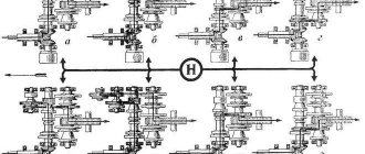
To increase cross-country ability and reduce wheel slipping, differential and brake locks are used on tractors. Switching is performed mechanically, manually or automatically from a separate drive. The MTZ-80 blocking system, which includes a hydraulic system, has this design.
Rear axle differential lock MTZ-82.1
locking clutch
The multi-disc hydraulically controlled differential locking clutch of the rear axle of the Belarus MTZ-82.1, 80.1 tractor is located in housing 8, which is bolted to the housing through the housing of the left double-disc (three-disc) brake and the bearing housing.
The housing 16 of the double-disc dry service brake contains brake discs 15, pressure discs 12, balls 11 and tension springs 17.
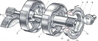
Fig.56. Rear axle differential lock clutch Belarus MTZ-82-1, 80-1, 82-2
1 — locking clutch; 2 - adapter; 3 — diaphragm cover; 4 — pressure database disk; 5 - diaphragm; 6 — squeezing disk; 7 — intermediate disk; 8 — BD coupling casing; 9 — coupling body; 10 — friction disc of the locking clutch; 11 - ball; 12 — brake pressure disc; 13 – differential crosspiece; 14 – locking shaft; 15 – brake disc; 16 – left service brake casing; 17 — tension springs.
The clutch consists of a locking shaft 14 connected through splines to the differential cross 13, a housing 9, a pressure plate 4, a release disk 6, a diaphragm 5, a cover 3, an adapter 2 and disks 10 mounted on the splines of the left drive gear of the final drive.
When oil is supplied from the hydraulic control system of the database under pressure into the working cavity “A”, the diaphragm 5 with the pressure disk 4 moves and presses the disks 10 against the supporting surfaces of the housing 9, the intermediate disk 7 and the release disk 6, blocking the differential (the differential cross with the left side gear) .
Differential lock control
Controlling the rear axle differential lock using a pedal
The rear axle differential lock control Belarus MTZ-82.1, 80.1, 82.2 consists of a locking valve, a pedal installed on the cabin floor, oil pipelines and hydraulic fittings.
The differential lock is controlled from the cab by a pedal, which acts through levers on the lock valve located under the cab floor.
The differential lock valve is built into the HPS drain hydraulic line and controls the flow of oil supplied to the lock clutch.
The control pedal for the differential lock of the rear axle Belarus MTZ-82-1, 80-1 has two positions:
— “Lock off” – the highest position of the pedal (the pedal is not pressed);
— “The locking is forcibly engaged” – when you press the pedal all the way and hold it in this position. Used for short-term blocking of the rear wheels when overcoming road obstacles during field and transport work and when performing various works with significant relative slipping of the rear wheels. The position is not fixed - when the pedal is released, it returns to its original position “Lock off”.
In the off position (the pedal is not pressed), oil from the steering metering pump freely passes through the lock valve and drains into the oil tank.
When you press the pedal, the levers turn the spool of the locking valve, which directs the flow of oil under pressure from 0.9 to 1.3 MPa into the locking clutch and the differential is locked.
When the pedal is released, the return spring lifts the pedal, the spool rotates to its original position, the oil from the locking clutch is drained through the locking valve into the hydraulic system oil tank and the clutch is unlocked.
Fig.57. Rear axle differential lock control Belarus MTZ-82-1, 80-1
1 – plug; 2 – valve body; 3 – bushing; 4 – bracket; 5 – washer; 6 – cotter pin; 7, 14 – washer; 8, 13, 22 – spring washer; 9, 12, 17, 19, 21 – bolt; 10 – pedal; 11 – lever; 15, 16 – spring; 18 – spool lever; 20 — bracket; 23 – adjusting washers; 24 – stopper; 25 – valve; 26 – spring; 27 – ring; 28 – emphasis; 29 – guide; 30 – spring; 31 – ball; 32 – spool; 33 – ring; 34 – pedal pad.
Cable control of rear axle differential lock
The differential lock system consists of a locking clutch, a lock sensor, a pressure reducing valve, oil lines and a remote lock control from the cab.
The differential lock is controlled from the cab by handle 9, which is connected by cable 2 to valve 1 of the lock sensor located in the power steering housing.
The differential locking handle of the rear axle Belarus MTZ-82.1, 80.1 has three positions:
— “Differential lock off” – extreme forward position along the tractor (the valve mark coincides with the “OFF” mark on the sensor cover);
— “Automatic differential lock” – the handle is in the middle position and is locked by turning it 90° clockwise (the valve mark coincides with the “ON” mark on the sensor cover). Oil under pressure from 0.8 to 1.2 MPa, supported by pressure reducing valve 28, is directed into the diaphragm cavity A of the locking clutch and the differential is locked. When the tractor's guide wheels are turned at an angle of more than 13° from straight-line motion, the rack 26 moves so that the spool 4 comes out of the rack groove, cavity A of the locking clutch communicates with the drain, and the differential is unlocked. Use automatic differential locking when performing all types of field work, as well as when performing transport work on dirt roads in conditions of insufficient adhesion of the drive wheels to the road surface. When performing transport work on paved roads in conditions of good traction, turn off the automatic differential lock to prevent increased tire wear;
Front drive axle of MTZ 82 tractor diagram
1 — track adjustment mechanism; 2 — bridge cover; 3 — cuff body; 4, 20 and 21 - shims; 5, 23 and 25 bearings; 6 and 28 - nuts; 7 — driven gear; 8 — drive disk; 9 - pressure cup; 10 and 11 — differential housings; 12 — driven disk; 13 — breather; 14 — bridge body; 15 — semi-axial gear; 16 — side gear plug; 17 — differential bolt; 18 — satellite axis; 19 — satellite; 22 — drive gear cup; 24 - drive gear; 26 — adjusting washers; 27 — connecting flange; 29 — wedge; 30 — half-frame beam; 31 — beam bushing; 32 — locking strip; 33 - swing axis.
Design of the front drive axle MTZ 82
The design of the front drive axle of the MTZ 82 is exactly the same as the non-drive, portal type (the beam is located above the wheel axis). This allows for a high (650 mm) agrotechnical clearance, which is an integral assistant for inter-row cultivation of tall row crops.
The main gear of the front axle of the MTZ 82 tractor is represented by a pair of bevel gears. In order to improve smooth engagement and quiet transmission, bevel gears are manufactured with spiral teeth.
The differential ensures different rotation speeds of the drive wheels when turning the tractor, as well as when driving over various uneven surfaces.
Also, when making turning easier, the differential can worsen the traction capabilities of the tractor. In order to avoid such a problem, tractors of this type use an automatically operating mechanism.
Front axle gearbox MTZ-82
The wheel gearbox of the MTZ-82 front axles is designed not only to increase the torque transmitted from the main gear to the main wheels, but also to rotate these wheels.
The gearbox itself consists of two pairs of upper and lower bevel gears.
With such an axle, all the parameters of its versatility are completely preserved on the tractor - the limits of track adjustment, mounting locations for aggregated machines, turning radii, agrotechnical clearance.
The front driving axle is installed in the opening of the front beam of the semi-frame in the same place where the front non-driving axle is mounted. The front axle housing is hingedly connected to the beam by two hollow axles, which allows the front axle to swing relative to the half-frame in the transverse plane.
Design of the hydraulic system for automatic differential locking MTZ-80 (MTZ-82)
The hydraulic system of automatic differential locking (ABD) is used to lock and unlock the differential of the rear axle of the MTZ-80 (MTZ-82) tractor, depending on the position of the guide wheels. It consists of a hydraulic sensor located in the rack stop 30, power steering, and a friction clutch mounted on the locking shaft of the rear axle of the tractor. The sensor, the working pressure cavity of the friction clutch and the drain line are connected to each other by pipelines 28 and 6.
Rice. Differential lock sensor for tractor MTZ-80 (MTZ-82): 1 — rack stop (sensor housing); 2 - pusher; 3 - spool; 4 — control valve; 5 retaining ring; 6 — clamp spring; 7 — ball retainer; 8 — control valve handwheel; 9 — sensor cover; 10 - sealing rings; 11 — spool spring; 12 — mark; 13 - dipstick.
The differential lock sensor consists of the following parts:
- housing 1, the role of which is played by the power steering rack stop;
- spool 3, held in a certain position by spring 11 and pusher 2 of control valve 4 with handwheel 8;
- cover 9, in which a locking device (ball 7, spring 6 and plug) is installed for setting valve 4 to the “On” and “Off” positions and a probe 13 for correct installation of the guide wheels when adjusting the toe-in.
Spool 3 has a hollow structure and two drillings perpendicular to its axis. There are two annular grooves on the outside of the spool. At the end of the pusher 2 there is a ball pressed into place, which fits into a special recess in the rack 31. When the tractor turns, the rack moves and the ball comes out of the recess and moves the spool in the axial direction.
Control valve 4 has a cylindrical cavity inside, closed at the end with a plug. The hollow part of the tap has three drillings in the diametrical direction. In the part of valve 4 that is located in the lid, two diameter recesses are milled for the locking ball 7. The lid 9 and valve 4 are sealed in the body with rubber rings. On the outer surface of the handwheel 8 there is a mark (cutout) 12, which serves to install the valve in the desired position.
Rice. Mechanism for automatic locking of the rear axle differential: 1 — final drive driven gear; 2 — left axle shaft; 3 and 4 - sealing rings; 5 - pipeline coupling; 6 — diaphragm cover; 7 - diaphragm; 8 — connecting disk assembly; 9 — intermediate disk; 10 — blocking clutch housing; 11 — locking shaft; 12 — left drive final drive gear; 13 — differential crosspiece; 14 — driven gear of the head drive; 15 - cavity for supplying working fluid to the differential lock clutch.
MTZ-80 steering conversion kit. MOUNTAIN MTZ-80
How to easily convert signal lighting to LEDs?
The hydrostatic steering control of the MTZ-80 tractor (MTZ-80 mount) is designed to control the direction of movement of tractors (in particular the MTZ-80 tractor with a non-driving front axle) and to facilitate the work of the tractor driver. The basic operating diagram and connection diagram are presented below.
There are several main possible ways of completing the MTZ-80 mountain control system.
The main kit we offer for re-equipment of the steering control for the MTZ-80 (MTZ-80 MOUNT) includes the following components:
- Bracket for hydraulic cylinder TsS-50 on MTZ-80 (F80-3001011);
- Steering rod from MTZ-1220, reinforced with mount (1220-3003010);
- Steering lever MTZ-80 left with mount (70-3001040-01);
- Steering lever MTZ-80 right with mount (70-300104);
- Steering hydraulic cylinder MTZ Ts50-3405215A;
- Pins F80-3405101B to hydraulic cylinder Ts50-3405215A;
- Length 125.00 mm;
- Threads: M20x1.5/M20x1.5;
- Maximum cone diameter: 29 mm;
The hydraulic cylinder pins of the HPS are included in it;
- Kit for replacing the pivot hydraulic cylinder pin TsS-50, F80-3405108 / F80-3405102 / F80-3405107 / F80-3405103
- Set of MTZ steering cylinder pin seals, F80-3405109;
Dispenser pump with a volume of 160 cm3 (in the literature the following alternative names are found such as hydraulic steering wheel, spool valve); Adapter for metering pumps with splines for the shaft (splined roller); High pressure hoses (HHP) wrench S24, 1.5 m long with a fitting at an angle of 90 degrees on one side;
Operating principle of the automatic differential lock (ADL) system
The automatic differential lock (ADL) system works as follows. The working fluid from the drain pipe 6 of the hydraulic booster, in which the pressure reducing valve 11 maintains a pressure of 0.8 MPa (8 kgf/cm2), flows to the blocking sensor tap. Further movement of the liquid depends on the position of the valve. When valve 4 is installed in the “On” position, the working fluid under a pressure of 0.8 MPa enters cavity A of the friction clutch, which blocks the differential crosspiece 13 with the left drive gear 12 of the final drive. When the tractor's guide wheels are turned at an angle of more than 8°, the power steering rack displaces spool 3, thanks to which the working cavity A of the clutch communicates with the power steering tank. Therefore, the pressure drops in cavity A of the clutch and the differential is unlocked. When the valve is set to the “Off” position, cavity A of the friction clutch is constantly, regardless of the position of the spool, in communication with the hydraulic booster tank and therefore the differential of the rear axle of the tractor is unlocked. Turning the automatic locking on and off is carried out by turning the flywheel 8 of the control valve. In the “Off” and “On” positions, the valve is fixed by ball 7, while mark 12 on the handwheel is set against the corresponding mark on sensor cover 9. The locking is activated only when there is significant slipping of the rear wheels of the tractor during field work and to overcome difficult areas when transporting goods. Operating the tractor with the differential lock constantly engaged on hard soils and roads is prohibited. With the lock turned on, the speed of the tractor when transporting goods should not exceed 10 km/h.
Other conversion options
In my opinion, the option with a hydraulic or pneumatic drive for the operation of the standard friction locking clutch is worthy of attention. Despite the exclusion of the automatic mode sensor, in this version the standard clutch remains. This allows for gentle forced locking without overloading the transmission.
Alternative hydraulic locking drive
Instead of supplying oil from the sensor, a working brake release cylinder from any vehicle with hydraulic brakes is installed. The working fluid is supplied to the cylinder from the master brake cylinder installed in the cabin. The cylinder control drive can be implemented either by a pedal or by an additionally installed fixed sector lever from the handbrake. When the liquid acts on the master cylinder rod, its pressure will squeeze the working cylinder rod, which, with its working stroke, will clamp the friction discs of the tractor locking clutch.
Practitioners also have experience in supplying pressure to drive the locking clutch from the free section of the hydraulic system distributor. To reduce the operating pressure, a pressure reducing valve is built into the supply line, releasing excess pressure into the drain.
Pneumatic locking
In the same way, you can organize a pneumatic drive for turning on the locking clutch from the tractor air system. The pressure supply is controlled by an additional air valve powered from the receiver. Instead of an oil tube, an air hose is connected to the locking fluid coupling through a fitting. When pressure of 6-7 atmospheres is applied to the membrane chamber of the clutch, the friction discs of the device are connected and the differential is directly blocked.
Main malfunctions of the automatic differential lock (ADL) system
The main malfunctions in which the automatic differential lock does not work are:
- Spool 3 of the steering angle sensor is stuck. It is necessary to remove the sensor and wash it in clean diesel fuel or replace the sensor.
- Low pressure of the working fluid in the pipeline to the lock-up clutch. It can be caused by a maladjustment of the pressure reducing valve or increased leakage of the working fluid in the sensor. In the first case, it is necessary to adjust the pressure reducing valve and caulk the valve seat, and in the second case, replace the sensor.
- Unsatisfactory operation of the differential lock friction clutch. The clutch does not work well for two reasons: the clutch discs are oily or the friction linings of the clutch discs are worn out. In the first case, it is necessary to eliminate the leakage of working fluid and wash the clutch discs in gasoline, and in the second case, replace the friction linings with new ones.
Design and principle of operation of the MTZ lock
On Minsk tractors there are 2 locking drives:
The mechanical locking device consists of a pair of jaw couplings, which are located at the inner ends of the final drive drive shafts. The ends of the shafts are splined, which ensures the mobility of the locking elements. The first coupling is installed rigidly and secured against axial play with a screw. The second coupling has the ability to move along splines.
For movement, an adjustable rod is used, which is connected to a separate pedal installed in the operator’s cabin. Pressing the pedal causes the clutch to move. After the cams of the movable clutch engage with the cams of the fixed unit, the final drive shafts are connected. To disengage the lock, you need to release the pedal.
When using a hydraulic drive, a friction type clutch is installed on the left final drive shaft in the transmission. Control is carried out using a distribution valve. The clutch discs are connected to the final drive shaft splines and grooves on the clutch body. The clutch housing part is rigidly connected to a special blocking shaft, which is passed through a hole in the final drive drive gear. The other side of the clutch is connected by splines to the differential spider.
The fluid is supplied to the dispensing unit of the lock activation sensor through the power steering drain line valve. The valve is set to maintain a constant pressure of 0.8 MPa. The dispensing unit is a manually operated valve with two positions - “on” and “off”. In working positions, the control handle is fixed with a stopper (a ball with a spring).
When the tap is opened, liquid is supplied to the cavity located inside the friction clutch. The fluid pressure on the clutch discs connects the drive gear (connected by splines to the left axle shaft), the locking shaft and the differential cross into a single chain. The resulting chain is a single axis, since the differential pinions are not able to rotate relative to the axle drive gears.
Deviation of the tractor guide wheels from straight-line motion by 8° (on some machines by 13°) or more moves the spool valve located in the activation sensor. When the valve opens, the fluid in the clutch cavity receives communication with the power steering reservoir. The pressure decreases and the differential spider begins to rotate. When the valve is in the “off” position, the coupling cavity is permanently connected to the power steering reservoir. In this case, the differential cannot be locked.
Since 2004, MTZ-80 tractors began to be equipped with a metering pump instead of power steering. The system uses a common oil tank for the rear linkage hydraulic system and the wheel steering drive. The principle of switching blocking modes has not changed, but the circuit uses a modified sensor.
MTZ-50
The operation of the drive axle differential lock on MTZ-50 model tractors is based on a mechanical principle. The control is carried out by a pedal located next to the mass switch.
MTZ-80
Tractors use a hydraulic locking circuit. The splines were removed from the shafts in the gearbox to install mechanical drive couplings. The sensor can be controlled by a cable or a pedal.
The cable drive is equipped with a handle and provides 3 operating modes:
- The system is disabled. The handle is in the extreme forward position and is held by a latch.
- Automatic operation when the wheels are turned at an angle of 8°. The handle is fixed in an intermediate position.
- Forced engagement, regardless of the angle of rotation of the front wheels. The mode is activated by pulling the handle all the way and holding it in this position. When you release the handle, the system will automatically turn off.
Pedal control provides 3 modes. Forced activation is carried out by pressing the pedal all the way and holding it. After removing your foot from the pedal, the lock is released.
MTZ-82
The MTZ-82 tractor is a variant of the Model 80 machine with all-wheel drive. The front axle is equipped with a self-locking differential. It switches on automatically when any wheel slips.
The rear axle blocker circuit and control methods do not differ from the units used on the MTZ-80.
Mechanism design
Minsk plant tractors are equipped with a mechanical or hydraulic locking drive. The MTZ 80 hydraulic differential locking mechanism is more efficient and easy to operate, but somewhat less reliable. That is why buyers of used tractors often get copies that are not equipped with this mechanism at all, and the question arises of how to make a lock on the MTZ 80 in order to safely use the equipment for plowing and snow removal. With some experience, you can assemble and install the device yourself. Older tractors have a special spline for this unit.
Principle of operation
The mechanical lock is based on two jaw clutches. They are located at the inner ends of the final drive drive shafts. The first coupling is fixedly mounted, the second one moves along the splines. It is directed by a rod, from which a separate pedal is brought into the cabin. When you press the pedal, the clutch moves and its cams engage with the cams of the stationary unit, as a result of which the final drive shafts are connected. When the pedal is released, the lock is released.
Homemade MTZ blocking
A number of owners equip MTZ tractors with homemade mechanical locking devices.
The manufacture and assembly of the mechanics of the unit consists of several stages:
- Grind the surface of the final drive shaft.
- Make a sleeve in the shape of a spool of thread with slots inside. The bushing should move freely along the shaft splines.
- Place the base for the lever to control the hub on the final drive cover. Inside the cover there is a fork that contacts the inner end surfaces of the sleeve. The fork has 2 bearings that directly move the bushing.
- Bring the control handle into the cabin and equip it with position locks. When the handle moves, the sleeve moves and the locking clutch engages. The locking is activated at the operator's request and does not depend on the angle of rotation of the front wheels.
Installation of attachments
The tractor is equipped with a three-point rear linkage design, made according to the classical design. The device consists of 1 central, two longitudinal rods, braces and a power cylinder that raises and lowers attachments.
- Gear type oil pump;
- Motor driven;
- Hydraulic distributor with three sections;
- 2 or 3 cylinders.
MTZ-80 is operated with various attachments. For work you can use:
- Kuhn;
- Potato digger;
- Plow;
- Harrow;
- Hiller;
- Kosarka;
- Snow shovel and much more.
If necessary, the tractor can be equipped with a trailer. The design of the machine allows you to connect a generator.
Read additionally: How to turn on video on MTZ-80
Useful tips
The hydraulic locking system is used for field work and driving on snowy roads. It is recommended to use a blocker when plowing soil on slopes, since the system ensures that a straight path of movement is maintained.
When driving on paved roads, differential locking causes increased tire wear, so the device should be disabled.
Using a locked differential on a slippery road is allowed at a speed of no more than 10 km/h (due to the danger of the car skidding).
Major breakdowns and repairs
- Blocking spool valve jammed. Repair requires removing the connection sensor and washing it in diesel fuel. If problems persist, the sensor is replaced.
- Pressure drop in the locking drive lines. The cause may be a deformed valve spring or a stuck valve. The valve has a collapsible design and can be adjusted on a bench. The second reason is fluid leakage through internal cracks or damaged gaskets in the connection sensor. The sensor must be replaced.
- Clutch slippage occurs when the linings wear out or become oily. Requires disassembly of the unit and inspection of the disks. Oily components are washed with a degreasing compound, worn ones must be replaced. If traces of oil are detected, it is necessary to eliminate the cracks through which the working fluid leaks.
- Incomplete engagement of the mechanical drive clutch. It is necessary to adjust the length of the rod and remove play in the connections. It is possible that foreign objects may get under the drive pedal and must be removed.
When carrying out regular technical inspections, the locking drives operate reliably, without causing problems to the owner of the MTZ tractor.
Locking drive options
On agricultural machinery produced in Minsk, two types of systems are most often found:
The mechanical type system structurally consists of two couplings, which are located at the ends of the final drive drive shafts. The spline allows the locking elements to move freely. One of the couplings has a rigid attachment to the axial play. The second one moves freely along the slot. Movement is ensured by adjustable traction. The presence of a pedal in the operator's cabin allows you to freely turn the system off and on without stopping the machine.
A special feature of the hydraulic mechanism is the installation of a friction clutch on the final drive shaft on the left side. The system is regulated using a control valve. The coupling discs are firmly attached to the shaft splines in the housing grooves. The locking is activated by supplying hydraulic fluid to the dispensing unit. It, in turn, is made in the form of a manual tap with only two positions.
Enabling blocking works like this:
- the tap opens;
- a special liquid is supplied to the internal cavity of the coupling;
- under the influence of pressure, the drive gear, shaft and differential are connected into one chain.
When the lock is turned off, the flow of hydraulic fluid stops and the differential spider begins to rotate again.
Depending on the tractor model, the systems may vary:
- MTZ-50. Such machines are characterized by mechanical locking systems. The operator controls it using a pedal located in the cab.
- MTZ-80. Such models are equipped with a hydraulic circuit. Control is carried out using a pedal or a special cable.
- MTZ-82. All-wheel drive vehicles are equipped with an automatic differential. It turns on when tires slip on the road. When installing a hydraulic circuit, you cannot do without spare parts for the MTZ-82 front axle.
On some tractors of the latest models, the system may come standard.
How to enable blocking on MTZ
In most cases, blocking on MTZ can only be enabled manually. It is worth keeping in mind that when the lock is turned on, there is a high risk of the tractor skidding. Therefore, the lock can only be activated at a speed of less than 10 kilometers per hour.
It is necessary to secure two couplings, one of which will be in a static position, and the second in a dynamic position and secured to splines. the direction of this coupling is determined by the rod, which is adjusted using a pedal located in the cabin. When the pedal is pressed, the dynamic clutch moves and connects with the static clutch. In this way the shaft bridges are combined. If you release the pedal, the lock will disengage. The column is in constant motion using cables. For more information on how to enable blocking, see the video below.
Have you modified the differential lock on your MTZ?
Homemade systems: pros, cons and assembly features
Some car owners prefer to install homemade mechanical locking devices rather than factory ones. There may be a number of reasons for this - from saving on the purchase of factory parts to the lack of spare parts with the required technical characteristics in the assortment.
The assembly sequence is as follows:
- grooving the surface of the final drive shaft;
- recess of the sleeve (ideally it should be similar to the shape of the thread spool);
- placement of the base for the lever on the top cover of the side gear (it is necessary for convenient control of the sleeve itself). In this case, a plug is installed on the inside of the lid. The element must be equipped with two bearings to move the sleeve;
- bringing the control handle into the operator's cabin. It must be securely fastened with clamps. When adjusting the handle, the clutch moves and the locking is activated.
Thanks to this system, ease of control is achieved. The system locking is not related to the steering angle of the front wheels.
Important Tips
The hydraulic locking system is indispensable during field work. It also makes it easier to control the tractor on snowy country roads in bad weather. Experts strongly recommend using blocking when plowing soil on lumpy surfaces. This allows you to maintain the straightness of the trajectory.
Important! When driving on paved, dense country roads, the lock must be turned off. Otherwise, it may lead to premature tire wear.
When driving on a slippery surface, blocking is allowed at a speed of no more than 10 kilometers per hour to avoid skidding on the road.
Main types of breakdowns
Even with careful operation, the system periodically needs repairs. Malfunctions most often occur due to:
- spool jamming. To return the system to working condition, you need to remove the connection sensor and wash it thoroughly in diesel fuel. If the problem recurs regularly, it is better to replace the element with a new one;
- pressure drop in the drive. The cause of the malfunction is most often damage to the spring or jamming of the valve itself. Due to the fact that the element is collapsible, it can be adjusted directly on the stand. A drop in pressure can also occur due to fluid leakage through damaged gaskets. In this case, you cannot do without replacing the sensor;
- that the clutch is slipping. This occurs due to wear and oiling of the linings. Carefully disassemble the assembly and carefully inspect the discs. If the elements are coated with a layer of lubricant, they must be cleaned with a degreaser. When worn out, it is recommended to replace spare parts with new ones;
Important! Find and eliminate cracks through which fluid leaks. This will help reduce the frequency of cleaning and therefore reduce the likelihood of breakage.
- incomplete engagement of the clutch. Adjust the length of the rod, remove any play in the connections. If foreign objects or small stones get into the system, remove them.
Timely maintenance of the system guarantees a long service life of the locking system. With proper care, replacement of parts and cleaning, it works properly without creating problems for drivers or tractor owners.