The T-25 gearbox is an example of a design solution that simplifies vehicle maintenance in the field.
When developing this unit, attention was paid to replacing individual parts without removing and disassembling the gearbox.
This is important when a breakdown occurs far from technical service centers or when workshops have a limited range of equipment for repairs.
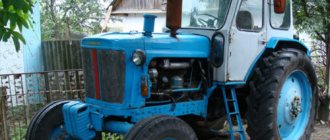
Appearing in 1966, at the same time as the T-28 model, the T-25 tractor turned out to be more in demand and popular.
The reason for this popularity lies in the concept of the machine, and in particular the design of individual components.
Transmission design
The T-25 tractor gearbox is made in a single block with a differential and main gear. The designers went to some extent to complicate the production technology in order to facilitate further maintenance of the unit and reduce its dimensions.
To do this, a bevel gear was placed on the input shaft, transmitting torque at an angle of 90 degrees to shafts and drive mechanisms located in a perpendicular plane.
If you look at the assembly drawing of the unit, you can see that the following are placed perpendicular to the input shaft:
- Hollow intermediate shaft. Inside this shaft there is a power take-off shaft, and outside there are gears for the second/fourth, first/third, fifth/sixth gears, as well as a reverse mechanism.
- The main shaft on which the retarder, doubler, first/second and slow gear gears, the third and fifth/sixth gear driven gears are mounted.
- Differential in a block with gears for accelerated and decelerated gears, as well as axle shafts.
The shafts rest on ball bearings pressed into the crankcase housing of the unit, access to which is provided after removing the mounting bushings or protective cups.
A device is installed on the crankcase cover that acts as a gear shift lock when the clutch is not fully depressed. It protects gear teeth from damage and premature wear.
Gearbox tractor T-25: basic repair and diagram
In this article we will look at the main points that are associated with the action and operation of the T-25 tractor gearbox. We will also provide a schematic diagram, briefly describe the principle of operation and the most common breakdowns that may occur. And of course we will give methods and ways to solve them.
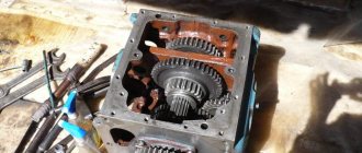
Gearbox of the T-25 tractor
The principle and diagram itself is quite difficult to understand, but we have focused on the main working units so that the study of the operating principle and possible breakdowns occurs in the shortest possible time.
All its working mechanisms and components are located in a solid body. In the front part there is a canonical gear, which is made together with the input shaft and the whole thing rotates on two ball bearings.
The mounting or front bearing is secured in a special cup using a retaining ring, while the rear bearing is located between the partition of the gearbox housing itself.
There are steel spacers under the front bearing flange. They serve to adjust the clearance of the side teeth and canon gears. In the middle part of the front shaft spline there is the main gear of the additional cylindrical transmission (see point 45) and the power take-off shaft.
The ball bearings and gear themselves are fixedly fixed to the shaft using a nut (49) through a sleeve (1). The self-clamping oil seal (2) is located in the bearing cup, which has a longitudinal groove for oil and to reduce the pressure load on the oil seal.
The reverse bevel gear (44) is permanently attached to the input shaft gear, which is fixed in the intermediate part of the main drive shaft.
To the right of the position of the reverse part of the T-25 tractor, a movable gear (5) is fixed on the intermediate shaft - 2nd and 4th gears, on the left is a double movable gear (5) - 1st, 3rd, 5th and 6th gears.
Also in the moving gears there are annular recesses for the gear shift fork themselves.
The intermediate shaft is mounted into the gearbox housing of the T-25 tractor and it is located on two radial bearings (9, 41). It also transmits rotation to the main shaft (24). The built-in movable doubler gear is fixed in the middle part.
T-25 tractor gearbox diagram
Below we have provided a diagram of the T-25 tractor gearbox, with a detailed description of each item and detail.
Let's continue, at (32) there is a gear that is responsible for the rotation of the differential housing.
What is the differential of the T-25 tractor
A device made of gears that transmits rotation to the main wheels and allows them to turn at different speeds is called a differential.
At the same time, the revolutions themselves and its rotation frequency remain constantly the same.
In the lower area of the T-25 gearbox there is a unit for additional low gears and the power take-off shaft drive itself. The PTO is located along the axis itself, its rotation is carried out using two bearings.
The movement of the movable gears of the gearbox is carried out by switching the forks and drivers. They are located on special shift shafts.
These shafts are located above the main shafts of the tractor gearbox and their movement is carried out along a bore in the side wall of the main gear housing.
The locking mechanism itself performs the function of turning on or off the gears and the reverse clutch with the clutch disc. Also, the locking mechanism prevents spontaneous switching off of reverse gear when the tractor is moving.
At the top of the main gear cover there is a mechanism that is responsible for switching the reverse and doubler gears. Below is a diagram of the position of the main gear gears when the others are engaged.
Remember that all mechanisms are located inside and are lubricated by the splashing effect of internal oil. The oil level is checked by inspecting the plugs located in the lower front and left walls of the block.
Basic repair of the T-25 tractor gearbox
Before starting repair work, you need to open the transmission housing housing and remove the bearing cover, which is located on the left side of the main shaft. Then remove the PTO cover (mode take-off shaft) on the right.
Unscrew the clamping pin and the spacer bushing. This will allow you to remove the cup with bearings.
If you need to remove the reverse, then remove the lock washer, it is located to the left. It is enough to turn it 30 degrees and remove the stopper from the bearing.
We carry out the assembly in the opposite order. During repairs or diagnostics, we carefully examine all parts. If we find them close to wear, we replace them.
agromania.com.ua
Device Features
The design features of the T-25 gearbox allow partial disassembly of the unit without removing it from the tractor. At the same time, the characteristics of the node necessary for operation are preserved:
- The number of gears necessary for the smooth running of the machine under load. The gearbox of early releases has six stages for moving forward, four backward, and later ones, eight and six.
- Gear ratios are optimally selected and allow you to realize the capabilities of the engine.
- Reserve resource and strength required for long-term operation.
The box is equipped with a power take-off shaft, necessary for the operation of attachments.
With the change in the number of stages, the gearshift pattern of later years of production changed.
The algorithm for switching reverse and doubler remains the same. For this purpose, a separate lever is provided in the tractor control.
Gear shift diagram for tractor T-25
In today’s article we will look at what seems to be a question from the basics of driving a T-25 tractor, but it is quite often found on forums and in the social circle of tractor drivers. Let's also pay attention to some subtleties and repeat the basics of correct operation of the clutch. All these recommendations will help extend the life of the machine and avoid most of the ridiculous breakdowns.
How to change gears correctly on the T-25 tractor
Let us immediately note that the entire procedure is performed using levers and handles. Let's start right away with the principle of operation of the shift and consider in detail starting from the first releases of tractors. The levers themselves used for shifting gears are installed only on the first releases of T-25 tractors. They serve to select the required gear, change the traction of the car or its speed. The lever must be moved forward away from the driver or backward, then tilted to the left or right.
We have shown all possible positions of the levers in the diagram below.
If the lever is moved forward, it will turn on the USK (high) or LAM (low) stage of the tractor doubler. In order to put the tractor into reverse mode (RR), move the lever first to the rearmost position, then to the right.
Shifting gears, doublers or reverse must be done with the clutch completely disengaged.
There are few differences in the latest release models - all switching is performed using one lever.
T-25 tractor gear shift diagram
We provide you with a diagram for all existing modifications of the tractor, which is still relevant today.
The first diagram is the switching scheme itself on first-generation tractors, the second is the reverse and doubler. The last picture is the switching used in the latest modifications of the release.
agromania.com.ua
Lubricants
For normal operation in the transmission, it is recommended to use mineral oils with a viscosity of W90 that meet the GL-3 standard. T-25 is a tractor developed at a time when the quality of transmission oils was quite low.
Due to the design features of the components, the use of synthetic lubricants of low viscosity can lead to gearbox failure.
The used lubricant is removed through a hole that is easily found in the lower part of the crankcase. There is a hole in the left wall of the crankcase to control the level and fill in new lubricant.
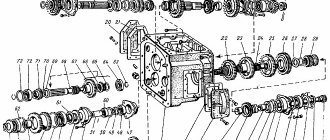
Design and operation of the T-25 tractor gearbox
All components and mechanisms of the T-25 tractor gearbox are located in a cast housing (position 6 in the figure). The input shaft (pos. 48) of the gearbox is made integral with the bevel gear and is located in the front of the housing, rotating in two ball bearings. The front (installation) bearing (pos. 3) is secured in the cup (pos. 47) with a retaining ring, the rear bearing (pos. 4) is located in the partition of the gearbox housing.
Steel gaskets (item 46) are installed under the flange part of the front bearing cup, with the help of which the lateral clearance of the bevel gear teeth is adjusted. In the splined middle part of the input shaft there is a drive cylindrical gear (item 45) of the additional transmission and PTO. The gear and ball bearings are clamped motionless on the shaft with a nut (pos. 49) through a spacer sleeve (pos. 1). The installation bearing cup contains a self-clamping frame oil seal (item 2), the lower part of the cup has a longitudinal groove for oil drainage, as well as for relieving the oil seal from oil pressure. The input shaft gear is constantly engaged with the bevel driven gears of the reverse mechanism (pos. 44), which is mounted on the intermediate shaft (pos. 42) of the main gear in its middle part.
To the right of the reverse mechanism of the T-25 tractor, a movable gear (item 5) of the second (fourth) gear is installed on the intermediate shaft, and to the left is a movable double gear (item 43) of the first (third) and fifth (sixth) gears. The movable gears have ring grooves for gear shift forks. The intermediate shaft is mounted in the gearbox housing of the T-25 tractor on two radial ball bearings (items 9, 41). The intermediate shaft transmits rotation to the main shaft (item 24). A movable gear (item 25) of the doubler is mounted in its middle part.
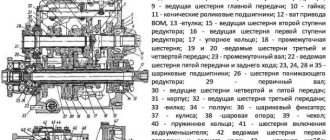
Fig. 1 — Gearbox (Gearbox) of the T-25 tractor
1 – spacer sleeve; 2 – self-clamping oil seal; 3, 4 – ball bearings; 5 – gear of the second (fourth) gear A25.37.228 z=21; 6 – main gear housing A25.37.122; 7 – adjusting shims; 8 – bearing cup; 9 – ball bearing; 10 – spacer sleeve; 11 – protective cap; 12 – spacer sleeve; 13 – bearing sleeve; 14 – oil seal socket; 15 – ball bearing; 16 – splined bushing; 17 – cover 7.37.130-A; 18 – clip; 19 – constant mesh gear 25.37.156 z=25, z=19; 20 – third gear driven gear 7.37.120 z=36; 21 – bearing cup 7.37.141-1 right; 22 – high-speed gear 25.37.152 (ring z=59); 23 – final drive drive shaft; 24 – main shaft 25.37.157; 25 – movable doubler gear 25.37.155 z=19; 26 – ball bearing 214K3; 27 – support spherical washer; 28 – adjusting washers; 29 – differential axis 7.37.146-4; 30 – satellite 7.37.147; 31 – slow gear gear 7.37.144-2 (ring z=66); 32 – differential housing A25.37.150; 33 – bevel semi-axial gear 7.37.145 z=27; 34 – self-clamping oil seal; 35 – driven gear of the fifth (sixth) gear A25.37.154 z=27; 36 – clip 25.37.220; 37 – cover 7.37.123; 38 – ball bearing 5038; 39 – gear of the first (second) and slow gear 7.37.119 z=42; 40 – retaining ring; 41 – ball bearing 406; 42 – intermediate shaft 14.37.301-4; 43 – gear of first (third) and fifth (sixth) gears A25.37.229; 44 – reverse mechanism; 45 – drive gear transmission to the drive roller A25.37.259 z=13; 46 – adjusting shims; 47 – bearing cup; 48 – input shaft of gearbox 7.37.102-1; 49 – nut.
From the main shaft, rotation is transmitted to the differential housing (item 32). The differential of the T-25 tractor is a gear mechanism that transmits rotation to the drive wheels of the unit and allows them to rotate at different speeds, while the speed of the differential housing remains constant. In the lower part of the gearbox housing of the T-25 tractor there is a unit of low additional gears and drive to the rear PTO. The additional transmission drive shaft is located along the axis of the housing, rotating in two bearings.
The ability to move the moving gears of the gearbox is ensured by shift forks and a driver, which are attached to the shift rollers. The rollers are located above the gearbox shafts and move along bores made in the side walls of the main gear housing. The gear locking mechanism is designed to eliminate the possibility of turning off or on gears, as well as the reverse gear clutch, when the clutch is engaged. In addition, the locking mechanism prevents spontaneous switching off of reverse and gears when the unit is moving. Shifting gears, doubler and reverse occurs using a mechanism located in the top cover of the main gear.
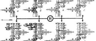
Fig. 2 — Diagram of the position of the main gear gears when engaging the gears (gearbox) of the T-25 tractor
a – first gear; b – second gear; c – third gear; g – fourth gear; d – fifth gear; e – sixth gear; g – first additional gear; and – second additional gear; 1 – input shaft of gearbox 7.37.102-1; 2 – reverse mechanism; 3 – intermediate shaft 14.37.301-4; 4 – main shaft 25.37.157; 5 – differential housing A25.37.150; 6 – movable doubler gear 25.37.155; The thick arrow indicates the transmission of rotation in forward motion, the thin arrow in reverse motion.
All parts located inside the gearbox are lubricated by spraying oil poured into the housing. The oil level is monitored using plugs that are screwed into the lower front part of the left wall of the housing. The oil is drained from the mechanism through a drain hole at the bottom of the housing, which is closed with a plug. The plug has a magnet designed to catch metal parts that get into the housing with oil.
recommended products
melagrocom.com
Reasons for failure
Thanks to the design features of the transmission, the repair of the T-25 tractor gearbox has been simplified, but other problems have arisen that should be given close attention:
- In adjusting the installation gaps of shafts, gears, bearings, and some other parts. This adjustment is made using special metal shims of varying thickness. Painstaking work requires special skills and patience. When done correctly, gears shift accurately, without additional effort, and the gearbox itself works correctly.
- Damage or deterioration of the seats of bushings and bearings leads to the fact that over time the cast crankcase body has to be replaced. To avoid this, the condition of the bearings and other components of the assembly should be monitored.
Despite the shortcomings, the resource of the box is long, and the performance characteristics are not satisfactory. The cause of malfunctions is the wear of some parts:
- Moving gears.
- Bearings.
- Clamps and rollers.
- Gear forks, reverse.
- Secondary shaft stops.
- Lock washer lugs, retainer cover.
- Primary shaft key grooves.
When repairing the box, pay special attention to the condition of these parts.
T-25 tractor controls and control devices
T-25 tractor controls and control devices
The location of the main controls and monitoring devices is shown in Fig. 4 and fig. 5. Switch 4 for lighting the instrument panel, side lights and headlights. Switch 5 for the taillight. Switch 2 for low-high beam. Instrument panel 6. Switch 1 for direction indicators. Button 3 for the sound signal. Lever 18 for controlling the fuel supply. When moving the lever forward ( to the engine) fuel supply and engine speed increase.
Rice. 4. T-25 tractor controls and control devices: 1 - direction indicator switch; 2 — low-high beam switch; 3 — sound signal button; 4 — switch for lighting the instrument panel, side lights and headlights; 5 — rear light switch; 6 — instrument panel; 7—switch for pre-heater and starter; 8 — “mass” switch; 9 — foot control pedal for fuel supply; 10 — brake blocking bar; 11 — right brake pedal; 12 — left brake pedal; 13 - latch.
Switch 7 of the pre-heater and starter. Switch 8 of the “ground”.
Tractor controls T-25
Rice. 5. Tractor controls: 14 — remote cylinder control lever; 15 — decompression device control lever; 16 — doubler lever; 17 — steering wheel; 18 — fuel supply control lever; 19 — trailer brake drive lever; 20 — reverse lever; 21 — gearbox control lever; 22 — clutch control pedal; 23 — main cylinder control lever.
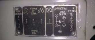
Clutch control - pedal 22. When you press the pedal, the clutch turns off, when you release the pedal, it turns on. Gearbox control - gear shift lever 21, reverse lever 20, doubler lever 16. The position of the lever handles when engaging various gears is shown in Fig. 6 and on the plate attached to the instrument panel. Changing gears and reverse is possible only with the clutch pedal fully depressed.
Rice. 6. Gear shift diagram for the T-25 tractor.
Brake control - pedal 12 (Fig. 4) of the left brake, pedal 11 of the right brake, lever 19 (Fig. 5) for driving the trailer brakes. The brake locking bar 10 (Fig. 4) is hinged on the right pedal; to simultaneously brake both brakes, the locking bar must be inserted into the slot of the left brake pedal. Latch 13 ensures the fixation of the pedals in the braked position, which is necessary to hold the braked tractor on a slope. For fixation pedals in the locked position, you must lock the pedals with bar 10, press the brake pedals all the way and turn the latch forward so that one of the latch teeth jumps over the finger welded to the left brake pedal, then release the pedals. To release the brakes of the tractor, you must press the brake pedals , after which the spring will return the latch to its original position. To brake the trailer, it is necessary to move the trailer brake drive lever back until it stops. Steering - steering wheel 17. When readjusting for long-term operation in reverse, the steering wheel is installed on the shaft shank. The direction of rotation of the steering wheel coincides with the direction of rotation of the tractor in forward and reverse motion.
Engine control of the T-25 tractor
Engine control - fuel supply control lever 18, fuel supply foot control pedal 9, decompression device control lever 15. When lever 18 is moved forward (towards the engine), the fuel supply and engine speed increase; when the lever is moved back, the fuel supply decreases; position of the lever, the engine stops. When you press the pedal 9, the fuel supply and engine speed increase, while the position of the lever 18 does not change. When you move the decompression device control lever 15 up, the decompression device is turned on and the compression ratio is reduced. When lever 15 is moved down, the decompression device is turned off. The power take-off shaft is controlled by a lever located at the right wall of the hydraulic lift housing. To turn on the power take-off shaft, the lever moves backward until it passes through the tide on the hydraulic lift body; to turn it off, it moves forward until it passes through the same tide. Turning on and off the power take-off shaft can only be done when the clutch is disengaged. Control of the pump and hydraulic system distributor - hydraulic pump drive lever and distributor levers. To turn on the hydraulic pump, it is necessary to pull up the handle of the hydraulic pump lever so that the latch comes out of the drilling in the hydraulic pump housing, and move the lever to the connecting body so that the latch enters the drilling of the housing. To avoid damage to drive parts, turn on the pump at low speeds engine. Lever 23 for controlling the main cylinder and lever 14 for controlling the remote cylinder. When the distributor levers are deflected up to full, the implement rises, the middle position of the levers corresponds to the neutral position, the lower position corresponds to the lowering of the implement, when the levers are deflected down to full, the floating position (main working) .
Rice. 7. Diagram of control of the distributor levers of the T-25 tractor.
The control diagram of the distributor levers is shown in Fig. 7.
traktor-t25.ru
Knowledge is never superfluous
The transmission structure of the popular T-25 tractor model shown in the diagrams at first seems overly complicated.
But in reality it’s not so scary, and you can carry out maintenance and repair of the unit yourself. Of course, with the necessary skills and tools. Did you find the article useful?
Stay on our website and expand your knowledge base about special equipment. For example, find out how to properly adjust the valves on the T-25 tractor, for what purposes the TT-4 crawler tractor was used, or what is good about the MTZ-80.
Carrying out repair and restoration work
Repair of the T 25 tractor gearbox is relevant if malfunctions in the operation of this system have begun to be observed:
- jerks, vibrations, knocking appeared;
- gears are difficult to change;
- not all speed modes are activated.
The exact reason why these manifestations began to be noted can be given by mechanics at the diagnostic center. However, such manifestations are due to the fact that the components of the box have worn out, for example, the secondary shaft, splines, bearings, bushings. In this case, the box must be disassembled.
You can add TM-5 gear oil from Lukoil to the gearbox. To drain the oil from the system, you need to unscrew the plug at the bottom of the housing.
It should be noted that there is a special magnet on the plug. Its main function is to attract metal particles that can get into the oil.
The need to repair the T 25 tractor gearbox does not often arise for owners of this equipment. By following the manuals and instructions for operating and repairing tractors, it is possible to eliminate the breakdown and extend its service life.
Engine repair
This tractor model has an engine with a cylinder (2 pieces) and an air cooling system.
Possible problems in engine operation and instructions for eliminating them:
- Air entering the fuel system prevents the engine from starting. In this case, it is necessary to rinse and blow out the fuel line, fill the fuel system with fuel to remove air. Rinse the filter.
- Poor atomization of diesel fuel by injectors. It is necessary to inspect them and eliminate the cause of the malfunction.
If the engine malfunctions or does not develop full power, then the cause of the problem may be the following:
- Air got into the fuel supply system and fuel and water were filled. It is necessary to remove the air and fill the fuel system with good, settled fuel.
- The nozzle needle is stuck. You need to rinse the sprayer and clean it with a drill or needle with a diameter of 0.25-0.28 mm.
- Fuel leak. It is necessary to adjust the fuel injection pressure of the injector, tighten the nuts or replace the high pressure pipe.
- The air cleaner is clogged. You need to wash this part and fill it with clean oil (without impurities).
Useful tips
The equipment must be used in accordance with the instructions.
In winter, operating the tractor becomes more difficult, so for stable operation of the unit it is recommended to do the following:
- Replace all summer types of lubricant with winter ones.
- Drain the fuel and rinse the tank with clean diesel fuel.
- Drain the fuel from the fuel line, replace the filters and pour a winter type of diesel into the tank, fill the system with it and completely get rid of air bubbles.
- Remove the battery and inspect it.
- Fuel must be filled through a suede or flannel filter.
- The tank must always be full. When filling, you need to make sure that no liquid gets into the fuel, because the resulting pieces of ice can clog the fuel wires and stop the supply of fuel.
- Once a day it is necessary to inspect the tank for the presence of water.
In order to carry out repair work correctly, it is recommended to use the book “Repair and Maintenance Manual for the T-25 Tractor”.