The URB 2A2 drilling rig is one of the most versatile in its class. The machine is designed to create explosive and water intake wells and explore various fields. In addition, it is used in the field of oil refining, geophysics, mining, and engineering geology. Let's consider its characteristics and features.
How does the car work?
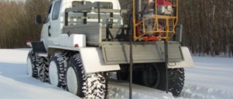
The standard URB 2A2 drilling rig is based on a reinforced load-bearing frame. It is mounted on the base of the modernized ZIL-131 vehicle. The truck has an increased cross-country ability, which allows drilling and exploration to be carried out in almost any conditions.
There is a moving hydraulic rotating mechanism with which you can perform the following manipulations:
- Raise and lower the drilling jig.
- Extend the length without leaving the face.
- Improve the quality of drilling operations.
The hydraulic drive greatly facilitates the entire process. The element is controlled using a remote control from the driller's seat. This interaction guarantees sensitive and fast drilling. The kinematic design aggregates with the truck engine using:
- Drilling type pumps (NB-50, MN-250/100, NSh-10-EL).
- Rotating mechanism, compressor, hydraulic motor.
- Transfer and transmission boxes, power take-off unit of the installation itself.
Machines for drilling wells for water in St. Petersburg and Leningrad. region
We will not touch upon the topic of drilling for oil and horizontal directional drilling; we will consider installations for drilling for water.
There are three types:
- portable;
- small-sized;
- stationary;
Portable installations. They are a collapsible tripod, in the upper part of which there is an electric motor that drives the entire installation. Feeding is usually carried out by chain transmission. The power of such installations is negligible, drilling diameters are up to 100 mm, depths are up to 20 m, and a suitable soil section is required. It makes no sense to even describe what kind of well they can drill. In any case, in the Leningrad region they are used only in geological surveys - for example, the UKB 12-25 machine.
Next in ascending order are small-sized drilling rigs (MGBU and MBU). They are a smaller copy of real drilling rigs, using some parts, such as swivels and elevators, from the latter. Some are mounted on trailers, some are self-propelled. Technically, they can drill a hole, but since the mass and power are small, the diameter and depth of the hole are proportional to their size. Well casing only with PVC pipes and no cutting off of toxic perched water is a natural result of the operation of such installations. In some places, a well can be drilled into shallow sand, but its longevity is measured in days. Further ordeals during the warranty period, and eventually redrilling the well again.
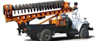
And finally, drilling rigs mounted on the chassis of trucks and crawler tractors. They are the only possible machines that can produce a long-lasting well with good flow rate that does not require maintenance. There are not many such machines - URB 2A2, UGB 1 VS, PBU 2, MBU 5, and a few less common ones. The chassis for them is KAMAZ, URAL, ZIL 131, GAZ 66.
URB 2A2 is a heavy and powerful rig, drilling depths up to 300m, and is mainly used in northern directions. PBU2 and UGB 1BC are mainly based on the ZIL-131 chassis, and are ideal for drilling in the south of the Leningrad region. The maneuverability of such vehicles is also important - when a KAMAZ or URAL enters a site, especially in the cramped conditions of our gardens, they will certainly demolish the neighbor’s fence, which, according to custom, is built on the side of the roadway, narrowing the already narrow passages. ZIL 131, and especially GAZ 66, will enter the site in several stages without spoiling the landscape and the mood of the neighbors. In the south of the Leningrad region, drilling wells with these machines takes 1-2 days, after which you will be provided with water for the next 50 years.
Want to discuss your well?
We suggest drilling a water well on your property, or blowing out an existing one. We will be happy to answer any questions you may have.
burgeospb.ru
Description of the URB 2A2 drilling rig
The equipment in question can also be installed on a tracked or sled-type base. These options are included as optional extras. It is made to order, since the URB 2A2 operates from a power unit of its own wheelbase; the machine is not capable of operating autonomously without providing additional power.
The main advantage of the technology under consideration is the design, which is entirely made using domestic technology using exclusively Russian parts. This factor makes it possible to reduce the cost of operation without losing quality. In addition, special equipment has high maintainability with the ability to order the required spare parts with the fastest possible delivery. Since all consumables are produced at specialized factories in Russia, when ordering parts there is no need to wait several months, as is the case with foreign suppliers. The URB 2A2 drilling rig can be operated in the most difficult conditions. The car performed well in Yamal and Yakutia.
Small-sized drilling rigs for drilling wells
The advent of small-sized drilling rigs has opened up new promising directions in the technology of drilling artesian wells.
The acquisition of such a unit by a company that has a fleet of heavy drilling equipment makes it possible to expand the scope of the enterprise’s activities by offering clients the construction of wells in hard-to-reach places, using drilling with a small-sized installation. Also, the purchase of such a unit can be the start of your own business.
Currently, the market offers a large number of different mini-rigs for drilling from both domestic and foreign manufacturers. They have different functionality and technical characteristics.
They can be classified according to several criteria:
- By design, portable, dismountable, trailed, self-propelled;
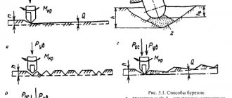
- According to the drilling method: auger, rotary, rotary, percussion-rope and others;
- The type of drive is electric (220 or 380 volts), hydraulic, from an internal combustion engine, gasoline or diesel.
- Portable dismountable rigs are the cheapest option for a drilling unit. The drilling depth is about 60 meters. Suitable for drilling soft sandy and clayey soils. Basic equipment allows you to deliver the device without special transport in a regular car and manually transport it to the drilling site. Such devices, as a rule, operate from an electric drive. Drilling wells with a small-sized drilling rig of this type is possible only in the vertical direction.
- A special place is occupied by small-sized horizontal drilling rigs, which are used for laying horizontal and inclined wells. Such devices are used when laying communication systems for electricity, water or gas pipelines, etc.
- Trailed MGBU belongs to the middle price category. Structurally, it is made in the form of a trailer for a passenger car. Drilling for water with units of this type can be carried out to a depth of up to 100 meters. Such installations can be used on medium-hard soils such as limestone, sandstone, etc. The main advantage is that drilling for water using small-sized installations - trailers - is carried out with minimal time and labor costs. Disadvantage: inability to work in hard-to-reach places.
- A crawler drilling rig is quite an expensive and powerful unit that allows you to drill to a depth of up to 150 meters; it can work in hard soils such as strong sandstone, granite rocks, etc. Such MGDUs can perform work at an angle, which makes it possible to equip wells on slopes. Tracked units can run on diesel fuel, electricity, or be equipped with pneumatics or hydraulics, which increases efficiency when digging difficult rocks.
A huge number of options and models of MGBU allows you to solve any problem related to drilling wells in construction, search and exploration of mineral deposits, water supply and other industries.
provides services for drilling wells for various purposes using the most advanced drilling rigs using the latest drilling technologies.
Source:
Peculiarities
This equipment is used for geological research, with the possibility of exploration at any level up to 300 meters. It is also used to create water intake wells constructed for the purpose of arranging water supply systems for various purposes (industrial and domestic use). A special feature of the machine is the possibility of synchronous washing or blowing of the processed drifts. It is worth noting that the overall process does not stop, which ensures uninterrupted work.
The connection and disassembly of pipes is carried out using screws using a rotator, which eliminates the use of additional devices. Thanks to the presence of a hydraulic cylinder that provides lifting and lowering manipulations, even when drilling with pneumatic hammers, the required constant pressure on the bottom is controlled.
Technical characteristics of the URB 2A2 drilling rig
Below are the parameters of the technical plan of the technology in question:
- The starting diameter of the work is 19 cm.
- Well drilling depth (geophysical/structural/auger/) – 100/300/30 m.
- The same indicator for blowing is 30 m.
- The maximum final drilling diameter is 11.8 cm.
- Speed (1/2/3 speed) – 140/225/325 rotations per minute.
- Torque (1/2/3 speed) – 2010/1210/830 Nm.
- The pressure indicator in the system is 100 kg/cm2.
- Loading capacity of the mast/tool – 6000/4600 kgf.
- Dimensions – 8.08/2.5/3.5 m. In working position, the height reaches 8.38 m.
- Weight – up to 13.8 tons.
- Compressor type – KSBU-4VU1-5/9.
Exploitation
The URB 2A2 drilling rig is equipped with a hydraulic system with pressure gauges that guarantee optimal operation of the mechanism. Using special filters, the oil is purified, which allows you to extend the operating life of the units several times. The installed mechanical type emergency pump allows you to manually deactivate the installation in the event of a vehicle breakdown.
Lifting of the working tool is provided in four modes: normal, emergency, fast and slow. It can be hung in any of the elevated positions thanks to the supporting retractable jacks. The tool can also descend in several modes. A simple but reliable hydraulic system allows full control of the unit without any problems.
The power take-off is equipped with one gear and a clutch. The part is fixed in the upper compartment of the ZIL transfer case housing. Activation of the transfer case of the installation itself is carried out via a cardan shaft and a power take-off unit. Using this block, rotation is transmitted to drilling and oil pumps.
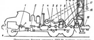
Rice. 1. Drilling rig URB-2A: 1 - car; 2 - mud pump; 3 — hydraulic jack for lifting the mast; 4 — food box; 5 — mast; 6 — crown block; 7 - swivel-drawbar - S - drive pipe; 9 — suppression mechanism; 10 - winch; 11 - rotor; 12 — drive lever of the feed mechanism; 14 — worm gear winch drive lever; 15 — rotor control handle; 16 — engine speed control handle; 17 — engine clutch control pedal; 18 — brake control lever of the right winch drum; 20 — mud pump control handle; 21 — control lever for the friction clutch of the right winch drum; 22 — control lever for the friction clutch of the left winch drum; 23 — rear mast support; 24 — front mast support.
The installation mast is hinged on the rear support, and during transportation it is laid in a horizontal position on the front support.
To operate at night, the rig is equipped with a lighting system consisting of three permanent and one portable points located on the crown block of the mast and at the driller’s workplace. Power for the light bulbs is supplied from the car battery.
The presence in the URB-2A installation of a double-drum winch with independent activation of the drums speeds up and significantly facilitates hoisting operations and the build-up of a drill string, and the presence of a feed mechanism allows you to create additional load on the bit when drilling shallow wells.
The figure shows the kinematic diagram of the URB-2A installation. The installation mechanisms are driven by the travel engine through the vehicle's gearbox and power take-off. Through the cardan shaft, the rotation from the power take-off goes to the transmission shaft. A pulley designed to drive a mud pump and a pulley used to drive a clay mixer and feed mechanism are freely mounted on this shaft. The rotation from these pulleys is transmitted through V-belt drives to the drilling pump, clay mixer and drive shaft of the feed mechanism. The mud pump drive pulley is connected with a gear coupling, and the clay mixer drive pulley is connected with a gear coupling. The cardan shaft of the feed mechanism is connected by a friction clutch built into the pulley. From this shaft, rotation is transmitted to a worm gearbox, consisting of a single-thread worm and a worm wheel, and through a system of sprockets and chain drives to the drill bit feed mechanism mounted on the mast.
From the transmission shaft of the installation, rotation is also transmitted through the driveshaft to the gearbox, and from it through a chain drive engaged by a gear coupling, to the winch shaft and through the driveshaft to the rotor. The oil pump of the hydraulic system of the installation also receives rotation from the gearbox. The gearbox is also used to change the rotation speed of the rotor and winch. Reverse rotation of the rotor and other installation mechanisms is carried out by engaging the reverse gear in the vehicle's gearbox. To avoid damage to the drilling rig components, operate at a speed of the travel motor of no more than 20 s-1.
Rice. 2. Kinematic diagram of the URB-2A installation. Positions are given in the text.
Rice. 3. Gearbox of the URB-2A installation. Positions are given in the text.
The power take-off transmits rotation from the travel motor to the drilling rig mechanisms. It is mounted on the top hatch of the car's transfer case, and is turned on using a lever from the car's cabin.
The gearbox is designed to transmit rotation to the winch, rotor and oil pump, as well as to change the rotation speed of the winch and rotor.
The drive and driven shafts, as well as the rotor and winch drive shafts, are placed on bearings in the gearbox housing. A gear and a block gear are mounted on the splines of the drive shaft, moving along the shaft with forks. The switching mechanism is equipped with a special lock that prevents the simultaneous activation of two gears. Gears and a drive bevel gear of the angular gearbox of the winch drive are attached to the driven shaft. By alternately connecting the pinion or block gear of the drive shaft with the corresponding gears of the driven shaft, three different speeds of rotation of the driven shaft are obtained, transmitted to the rotor and winch. The rotor drive shaft is connected by a gear coupling via a roller. The winch drive shaft rotates through the bevel gears of the angular gearbox. A winch drive sprocket is freely mounted on bearings on the winch drive shaft and is engaged by a gear coupling.
The oil pump of the installation's hydraulic system is mounted on the box body, the drive shaft of which receives rotation from the drive shaft of the box. The pump is turned on using a claw coupling through a roller.
The gears and bearings of the gearbox shafts are lubricated by spraying a disk of oil poured into the gearbox housing. Check the oil level with a dipstick.
The winch has two drums, freely mounted on a common shaft. One drum is designed to support the drilling string during drilling and lifting the swivel-stuffing box with the leading pipe when removing the drilling string from the well, and the second is for tripping and hoisting operations with the drilling string itself. The maximum lifting capacity of the winch is 2.5 tons.
Rotation is transmitted to the winch shaft from the gearbox by a double-row chain through a sprocket mounted on the winch shaft.
The winch drums are activated independently of each other by double-disc friction clutches, which are mounted in the drum brake pulleys. Their design is similar to the friction clutch of the winch drum of the URB-ZAM drilling rig. The friction clutches of the drums are engaged using levers.
Each drum has its own independently controlled band brake. The drum brake levers are connected to the brake bands by a system of rods and forks that allow the tension of the bands to be adjusted as they wear out.
The design of the rotor is basically similar to the rotor used in the URB-ZAM installation. The through hole of the rotor table is smaller than in URB-ZAM and allows casing pipes with a diameter of no more than 150 mm to be lowered through it.
Rice. 4. Winch installation URB-2A:
Rice. 5. Rotor of the URB-2A installation. Positions are given in the text.
In the rotor housing, on two identical angular contact bearings, there is a rotor table with a bevel gear attached to it. Rotation from the gearbox through the cardan shaft, rotor drive shaft and bevel gears is transmitted to the rotor table.
From the rotor table, through a special insert that has an internal square-section hole for the drive pipe and is inserted into the hole in the rotor table, rotation is transmitted to the drive pipe.
As in the rotor of the URB-ZAM installation, the rotating parts of the rotor are lubricated with oil poured into the housing, and to protect the oil from contamination by the flushing liquid, a ring lock of two protrusions is installed in the upper part of the housing, included in the ring supports of the rotor table. The oil level is monitored through the plug.
The mast of the installation is triangular, welded, designed for lowering and raising drilling and casing pipes. It is hingedly connected to the installation frame. In the working position, the mast is installed vertically, and during transportation it is laid on the front post of the frame in a horizontal position. Unlike the mast of the URB-ZAM installation, it is one-piece and consists of one section. Raise the mast into working position using a hydraulic jack. The front legs of the mast are equipped with screw jacks that relieve the rear axles of the vehicle. The mast's lifting capacity is 2.5 tons, and its height to the crown block axis is 10.7 m.
The mast is equipped with guides that serve to move the guide rollers of the swivel-gland during the drilling process, and also prevent rocking and turning of the body of the swivel-gland together with the drive pipe during drilling. In the upper part, the guides have a bend that allows you to remove the swivel-oil seal with the drive pipe (when moving the unit to the transport position and during hoisting operations). The design of the swivel-oil seal is similar to its design in the URB-ZAM installation.
At the top of the mast there is a four-roller crown block, the rollers of which are covered with a casing.
The drilling tool feed mechanism is located on the installation mast and creates additional load on the rock cutting tool. If the vehicle's engine fails, it can be used for emergency manual lifting of the drill.
Rotation is transmitted to the feed mechanism through a V-belt drive from the transmission shaft, through a cardan shaft, a worm gearbox and chain sprockets.
The installation uses a rope-chain feed mechanism. Ropes are attached to the cheeks mounted on the axles of the swivel-gland on one side, and single-row bushing-roller chains on the other. These chains go around the sprockets mounted on the feed mechanism shaft and are connected with ties to the ropes thrown over the two outer rollers of the mast crown block. As a result, a closed system is formed, which, when the feed mechanism shaft rotates, causes the cheeks with the swivel-seal attached to them to move, and with it the entire drill bit.
The mechanical feed speed is 6.3 cm/s, and the created load on the rock cutting tool is 20 kN.
When working with the feed mechanism, the drill bit is lowered onto the bottom of the well, completely releasing the brakes on the winch drum. The load on the bit is adjusted by turning the friction clutch on and off.
Rice. 6. Hydraulic system of the URB-2A installation. The arrows indicate the direction of oil movement: a - when lowering the mast; b— when raising the mast; c - from the pump to the distributor; g - from the tank to the pump. Positions are given in the text.
The hydraulic system of the installation is designed to lift the mast into the working position and lower it. It consists of an oil pump driven by the gearbox, a distributor with four valves, a hydraulic jack oil tank and oil lines.
Oil from the tank is sucked through the oil line by the oil pump and supplied through the oil line to the distributor. From the distributor it can flow through an oil line to the lower part of the hydraulic jack (to raise the mast), and through an oil line to the upper part of the hydraulic jack (to lower the mast) or through the oil drain line back to the oil tank. The distributor is equipped with a safety valve.
A double-action telescopic hydraulic jack is hinged at one end on the installation frame, and at the other end it is pivotally connected to the mast. Under the pressure of oil pumped by the oil pump, the hydraulic jack rods are gradually extended and the mast is raised to the working position.
Before raising the mast, all distributor valves must be open two to three turns, and after turning on the oil pump, close the mast lowering shut-off valve. In this case, the oil supplied by the pump through the mast lift valve is pumped into the oil drain line. By gradually closing valve 6, the amount of oil pumped into the oil tank is reduced, and it begins to flow through the oil line into the lower cavity of the hydraulic jack. As a result, the pressure in the hydraulic system increases and at a pressure of about 3 MPa the mast begins to rise. When the outer rod comes out of the hydraulic jack by 0.6 ... ... 0.7 m, by smoothly screwing in the mast lowering valve, the inner rod located in the outer rod of the hydraulic valve is pulled out, and, by regulating the oil supply with the valve, the mast legs are smoothly brought to the installation frame.
Fasten the mast with clamps to the frame, close the valves, and after turning off the oil pump.
Before lowering the mast, check the condition of the hydraulic system by fully opening the valves and closing the valves. Turning on the oil pump, gradually close the valve, increasing the pressure in the hydraulic system to 1.5 ... 2 MPa. If the hydraulic system is working properly, begin lowering the mast. To do this, the valves are opened and closed. Then, closing the valve, increase the pressure to 1.5 ... 2 MPa and check the condition of the oil lines coming from the top of the hydraulic jack, as well as the condition of the cuffs. If there are no oil leaks, valve 6 is unscrewed 1 ... 1.5 turns and, screwing the valve, the pressure in the hydraulic system is increased until the mast begins to deviate from the vertical.
Next, the speed of lowering the mast is regulated by valve 6. By completely closing it, you can stop lowering the mast in any position.
After the mast tilt is less than 45°, open the valve 1.5...2 turns, and the mast will lower only under the influence of its own mass. To avoid impacts and damage, the mast is laid on the front post at a minimum speed. Then turn off the oil pump and close all distributor valves.
Rice. 7. Lubrication diagram for the URB-2A installation.
Rotator
The rotation mechanism of the URB 2A2 drilling rig, the photo of which is available above, includes a box with three shafts and the same number of speeds, as well as cylindrical and gear elements. The rotator is housed in a cast steel housing, which ensures the strength and reliability of the unit. The control panel adjusts the spindle speed, from zero mode to maximum.
The hydraulic feed jack includes a rod and cylinder that takes part of the reaction load. The unit is equipped with one stage of pair action. The mast has a U-shaped configuration, made of channels with additional cross members. In the inner part there is not only a jack, but also two pipes on which the load is applied. This solution allows you to optimize the operation of the drill in difficult conditions. The centering table makes the tool easier to use.
Hydraulic cylinder for lifting rotator 2-25-10-1 URB 2A2
Position No. 10 on the diagram.
1. Purpose of the product Hydraulic cylinder 2 - 25 - 10 - 1 is designed to convert the pressure energy of the working fluid into reciprocating movement of the rod and for use in hydraulic systems of mobile stationary machines. 2. Design and principle of operation The hydraulic jack consists of a welded body, rod, piston, tips, front cover and sealing devices. The supply of working fluid is carried out through high pressure hoses. The hydraulic jack performs reciprocating movements under the influence of the pressure difference of the working fluid in the piston and rod cavities of the cylinder. 3. Operating instructions The hydraulic jack must be operated in accordance with the “Technical Description and Operating Instructions” of the product on which it is installed. Installation, dismantling and operation of the hydraulic jack must be carried out by personnel familiar with the “Technical Description and Operating Instructions”. Before starting work after installing the hydraulic jack on the machine, it is necessary to remove air from the hydraulic system. The spatial position of the hydraulic jack is arbitrary. When installing a hydraulic jack, it is necessary to ensure compliance with the direction of action of the force with the axis of the rod along the entire path of movement, as well as reliability. The hydraulic jack should be stored in a room with an air temperature of 5 to 40 degrees. C and absolute humidity no more than 80%. During long-term storage, preserve the threaded surfaces and the surface of the rod. 4. Transportation and packaging Transportation of the hydraulic jack is allowed by any type of transport. The packaging must ensure the safety of the jack during transportation and unloading and loading operations. 5. Certificate of acceptance Hydraulic cylinder 2 - 25 - 10 - 1 has a serial number and meets the requirements of the regulatory and technical documentation. The hydraulic jack is preserved during transportation. 6. Warranty obligations The manufacturer guarantees the jack’s compliance with the requirements of the design documentation provided that the consumer complies with the requirements of transportation, storage and operation. The warranty period is 12 months from the date of commissioning. But no more than 18 months from the date of shipment from the manufacturer, provided that the consumer complies with the operating, transportation and storage conditions. The warranty covers functional defects, defects in materials and components used. The warranty does not apply to wear and tear defects that arose during normal operation of the system or irregularities in equipment operation, installation, maintenance and repair. The warranty also does not apply in case of installation and operation on low-quality attachments and the base machine. The warranty does not apply if the defect occurs as a result of replacement of product components.
Technical characteristics Hydraulic jack 2 - 25A - 00
The piston stroke is 2640 mm. Piston diameter - 120 mm. Rod diameter - 80 mm. Working pressure - 10 MPa (100 kgf/cm2) Test pressure - 250 kgf/cm2 Operating temperature - from - 40 to + 70 degrees. C Force on the rod^ Pushing - 14.13 tons. Pulling - 14.13 tons.
List of sealing elements (spare parts):
Ring 60 * 55 * 3.2 - 1 pc. Ring 120 * 110 * 5.1 - 1 pc. Piston seal 120 * 95 * 22.4 - 1 pc. Support-guide ring 80 - 86 - 20 - 2 pcs. Rod seal 80 * 100 * 6.3 - 1 pc. Wiper 80 * 95 * 8.5 - 1 pc.
Possible malfunctions and ways to eliminate them:
Lack of operating pressure in the piston cavity - Replace seals Oil leaks along the rod - Replace seals Uneven movement of the rod with jerks, increased noise and vibration - Remove air from the cavities, eliminate the possibility of air leaks in pipeline connections and rod seals
Dimensions and weight for calculating transportation by transport companies: Length, mm 3250 Width, mm 500 (with support), 360 (without support) Height, mm 360 05/10/2018 Hydraulic jack 2 - 25A - 00 Weight, kg 250 (net), 270 ( gross) Volume, m3 0.486 (with support), 0421 (without support)
All products are of high quality and fully comply with all regulatory documentation requirements for this category of goods. Before delivery of finished products to the warehouse, all parts undergo strict technical control (QC). We work with all transport companies, individual approach to each client, promotions + discounts, the ability to manufacture non-standard products according to your drawings.
Other mechanisms
The URB 2A2 drilling rig includes a traveling system that allows doubling the stroke of the rotating device; it has a reinforced design with two tensioning devices.
The elevator is responsible for screwing or unscrewing working pipes and tools. It has a high-quality mount and device, and is easy to operate. Auger chucks make it possible to build up and lift assemblies safely while controlling drilling quality. The structural features of the rotational device allow for double the speed of movement. The mast is automatically transferred to the transport position in the event of failure of the drive motor or transmission. The base vehicle is unloaded using support jacks.
Design features of drilling equipment
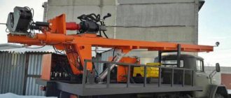
Drilling rig URB 2A2 based on ZIL 131
The main mechanism of the URB 2A2 drilling rig is mounted on a supporting frame, which is mounted on a ZIL-131. The standard equipment includes a two-axle trailer, which is used to transport the auger, pipes and working tools. Materials can be loaded and unloaded using a jib crane.
The drill rotates at a speed of 1800 rpm. The URB 2A2 drilling rig is equipped with an emergency oil pump, with which you can carry out emergency movement of the rotator and laying the mast. The operator monitors the drilling parameters through pressure gauges. Using the traveling system, the rotator can be doubled in speed.
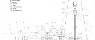
Scheme
Below is a schematic image of the URB 2A2 drilling rig, the characteristics of which were discussed above, as well as an explanation of the digital designations.
- Mud pump assembly.
- Power take-off box.
- Pump drive.
- Hydraulic type jack
- Compressors.
- Handout.
- Lifting cylinder.
- Rotational mechanism.
- Carriage.
- Elevator.
- Auger cartridge.
- Sealing unit.
- Working mast.
- Support jack.
- Traveling equipment.
- Control system.
- Basic vehicle.
- Frame.
- Distributor.
- Hydraulic unit piping.