History of creation
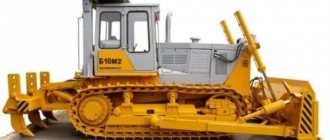
During the years when the Great Depression befell the American state, their company from Detroit signed a contract for the construction of a tractor plant located in Chelyabinsk. The base model of the future domestic tractor was the Caterpillar-60. Already in 1933, the first car rolled off the assembly line, named “Stalinets-60”.
During the difficult years of the Second World War, production facilities were directed to the production of self-propelled guns and KV tanks, tractors transporting howitzers. After the war, the Chelyabinsk enterprise produced a multifunctional tractor, the famous “weaving”. The unit broke several world records. The T-130 modification became a direct descendant of the famous Sotka. This bulldozer is still in mass production.
Purpose
Model T-130 is a wide-profile vehicle. It is used to perform the following actions:
- Soil movement.
- Backfilling of trenches.
- Construction of embankments.
- Reclamation.
- Site planning.
- Plowing.
- Loosening the soil.
- Clearing territories.
- Cleaning up waste at a construction site.
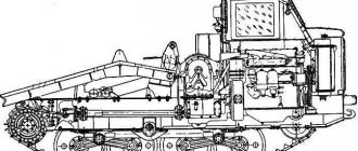
T-130 bulldozer diagram
Technical specifications
The technical specifications of this equipment are as follows:
- speed - 12 km/h;
- ground clearance - 0.42 m;
- track width - 1.88 m;
- blade width - 3.2 m;
- weight (how much it weighs with a blade) - 14.3 tons;
- pressure exerted on the ground - 0.05 m;
- diesel fuel tank size - 290.0 l;
- volume of the reservoir with hydraulic fluid to fill the system - 100 l;
- unit dimensions - 5.19 * 2.47 * 3.08 m.
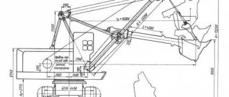
Dimensions of the T-130 bulldozer and main technical characteristics
Engine
The first cars of this brand were equipped with D-130 engines, but already in 1981 they were replaced with more powerful D-160 diesel engines. Their main advantages are unpretentiousness and guaranteed reliability. Over many years of operation, the engines demonstrate quite stable operation, despite extreme conditions.
But in severe frosts, the machine operators were unable to quickly start the mechanism. Because of this, those tractors that were sent to the northern regions were equipped with a pre-start heating system for both the engine and any technical fluids. The units demonstrate reliable operation on diesel fuel of any quality; they can be started on kerosene or gas condensate.
| Options | Values |
| Power | 170 kW |
| Number of cylinders | 4 |
| Cylinder volume | 13.5 l |
| Piston diameter | 145 mm |
| Piston movement | 205 mm |
| Crankshaft speed | 1070 rpm |
| Generated torque | 1098 Nm |
| Engine weight | 1.95 t |
| Fuel consumption | 236.3 g/kWh |
Transmission
The tractor is equipped with a mechanical or hydromechanical transmission system with eight stages. It has a clutch with four discs that is permanently closed to transmit rotation. Torque is transmitted by a gearbox with four shafts.
The unit is equipped with a two-stage final drive, multi-disc dry clutches, and a constantly meshed bevel gear. The presence of four shafts in the gearbox allows you to engage eight forward and four reverse gears. Maximum thrust is achieved at a speed of 2.6 km/h and has a value of 128.2 kN.
Removal and disassembly of the final drive T-170
Drain the oil from the final drive. Disconnect the track, remove the cab with the fuel tank and wings (see “Repair of the T-170 gearbox”), the final clutch, the drive wheel and the labyrinth seals.
Remove plug 6 (Fig. 247) from the keyway of axle shaft 16. Press out key 7 and remove rubber ring 5 and steel ring 4 from the axle shaft. Unscrew the nuts and bolts securing the final drive housing.
Sling the final drive casing behind the hole in the rib (Fig. 248). Screw two release bolts into the M14 holes, slide the casing off the pins and remove it.
Snap the hub (Fig. 249) with the gear and remove it from the axle shaft together with roller bearing 8 (see Fig. 247), sleeve 2, ball bearing and outer ring of roller bearing 17.
Use a socket wrench to remove six bolts 14 through hole C in the drive flange. Screw two M12ХК75 release bolts into the bearing housing.
Secure (Fig. 250) the drive flange with the gear and press the bearing housing out of the seat using the release bolts. Remove the drive flange with gear 15 (Fig. 247) from the side clutch compartment.
Sling the double gear. Gear weight 40 kg. Loosen and unscrew the nut (Fig. 251) and remove the clamp 3. Remove the double gear with the inner rings of roller bearings 4 and 9. Unscrew the six bolts 12 and remove the clamp 6. Using a copper mandrel, knock out the bearing housing 10 along with the rod, ball bearing and outer ring of the roller bearing . Press out the ball bearing together with the outer ring of the roller bearing and remove rod 5.
Disassembling the T-170 hub
Bend the ends of the locking plates 3 (Fig. 252) and unscrew the nuts from the bolts 5 securing gear 4 and ring 12 to hub 13. Knock out the bolts, remove them and strips 6. Remove the gear and ring. Press out the outer ring of roller bearing 1 with a puller and, if necessary, remove the retaining ring 14.
Turn the hub over with cover 10 facing up. Bend the ends of the locking plates 7 from the edges of the heads of the bolts securing the cover 10 to the end of the hub. Unscrew the bolts and remove the cover. Use a puller to press out ball bearing 9 together with the outer ring of roller bearing 8. If necessary, remove retaining ring 11.
Dismantling the T-170 drive flange
Unlock and unscrew bolt 14 (Fig. 253) and remove the locking plate. Unscrew the nut 42 from the end of the drive gear 5 and remove the metal ring 13 and the rubber gasket 11. Press the flange 10 from the splines of the drive gear. Remove the cover 9 from the housing and press the cuff 15 and the ball bearing 17 out of it. Press the outer ring 6 of the roller bearing out of the housing 18 with rollers and separator.
Dismantling the final drive casing T-170
Unscrew bolts 11 (see Fig. 247) and remove cover 10 with gaskets 9.
Unfasten and unscrew the bolts 6 (Fig. 254) and remove the clamps 7 and locking plates 5. Press the outer ring of the roller bearing 8 with the rollers and separator out of the casing 4 using a puller. Unscrew stopper 9 from the casing. Press out the outer ring of the roller bearing 3 c. rollers and separator.
The housing, pinion hub and double pinion can be removed without removing the cab, fuel tank or final clutch.
Chassis control
The suspension of the unit is semi-rigid and has a transverse spring for balancing. The frame is made from 2 stamped spars, which are combined with the rear axle assembly. The track web connects stamped tracks with metal pins.
The design of the chassis of the T-130 tractor
The installation is controlled by using a lever system through a set of belt clutches. To make a circular turn with a bulldozer, a rotary coupling is used. It is attached to the rear of the axle and connected to the drive gears through shafts. By using a band brake attached to a rotary coupling, it is possible to turn the machine almost in place, without moving.
The gear ring is fastened with twelve tight-fitting bolts 41 with nuts to the hub flange 42. The nuts are locked in pairs with plate washers.The large diameter hub 42 rotates on cylindrical roller bearings pressed onto the axle shaft. Roller bearings only support radial loads, while ball bearings support axial loads that occur when turning. A spacer 51 is installed between the outer and inner bearings; the entire package of parts is tightened onto the axle shaft with lock nut 14. During operation, the final drive bearings are not adjusted.
The cast drive wheel 55 is centered on the hub and secured to it with ten tight-fitting (precise) studs 16 and pressed nuts 17.
In the outer end part of the hub, 10 holes are drilled for fit pins 16. The drive wheel 55 is connected to the hub using split conical bushings 19.
Conical bushings 19 with compressed nuts 17 screwed onto the studs, the outer surface is in contact with the conical bores of the drive wheel 55, and the inner surface is in contact with the outer ground surface of the stud 16, forming a backlash-free connection.
The oil bath of the final drive is sealed by two metal mechanical comb seals (small and large). Each seal consists of a movable and stationary disk and a rubber lip.
The fixed disc of the small seal is floating, movable 5 is centered in the hub and rotates with it. The fixed disk 6 is pressed against the movable one by a central spring.
The fixed disk 54 of the large seal is also floating. It is prevented from turning by two crackers located on the axes, which fit into the grooves of the large seal flange. The movable disk 21 rotates together with the drive wheel. The large seal discs are compressed by radial springs spaced evenly around the circumference. Rubber cuffs are placed on the outer diameters of the stationary seal discs and are connected to the body parts.
The rubber cuff of the large seal is protected by a two-way labyrinth, the moving part of which 20 is connected to the drive wheel, and the fixed part 23 is connected to the casing.
The axle bearing 7 is mounted on the track bogie using two bushing pins and secured with four bolts.
Rubber sealing rings are installed between the large seal stationary washer and the labyrinth, as well as between the drive wheel, labyrinth and hub.
The bearing of the axle shaft 7 is secured to the cylindrical part with a nut 12. One end of the axle shaft is connected to the bearing, the other end is pressed into the conical hole of the rotation coupling housing and is additionally secured with a nut 47, locked with a special spring ring 46. Thus, the axle shaft is rigidly connected to the rotation coupling housing.
To ensure that the drive wheel is in the same plane with the tension wheel and the center line of the rollers, there are shims 8 between the axle bearing and the bearing cover.
The final drive gears and bearings are lubricated by oil sprayed from the rotating gears. Oil is poured into
final drive through the pipe located in the flange of the side wall of the rotation coupling housing, to the marks on the oil gauge line.
A magnetic plug 53 is screwed into the lower part of the final drive casing. A radial self-clamping seal is installed in the final drive between the drive flange 30 and the bearing housing 36.
The end bearing bushing is lubricated through a grease nipple screwed into its cover. This cavity is sealed with a radial self-pressing seal.
The final drive of a swamp tractor is different from the gearbox described above; Since the track of this tractor is 400 mm wider than the base track, some parts of the final drive (axle shaft 9 (Fig. 66), hub 3, spacers 1 and 2) are lengthened.
Cabin
The operator's seat is located in a cabin with panoramic glazing and a reinforced frame, which ensures a safe stay for a person inside. Factory designers competently designed the driver’s work area, carefully considering the location of all instruments and control levers so that the operator could comfortably perform the assigned tasks.
Engine control system for bulldozer T-130
T-130 cockpit and controls
The chair is equipped with convenient tilt and height adjusters, which ensures that the worker can achieve a posture in which he feels comfortable while working. Reliable insulation from dust and noise ingress is achieved using soft rubber seals. Thanks to the heating system, the room quickly heats up in cold weather.
Device
The T-130 bulldozer was equipped with a four-stroke diesel engine D-130 (140 horsepower), which became obsolete already in the 70s. Since 1981, the model began to be equipped with an improved four-cylinder D-160 turbocharged unit (160 hp). It was started using a gasoline engine. This installation was received by a significantly modernized version of the T-130 - the T-170 bulldozer.
The model received an 8-speed manual transmission, including a clutch (permanently closed), four discs (two driven, two driven) and a four-shaft gearbox. Bulldozers of this type were equipped with a floating, band brake system.
The ability to mount a power take-off shaft made the T-130 multifunctional, allowing it to be used with a variety of equipment for many industries. The operator's cabin in this model is located at the rear and is designed for two people. It has sound and thermal insulation, which allows you to “smooth out” unpleasant conditions outside and make working with equipment more comfortable. But the control of the bulldozer is far from ideal. During operation, a strong vibration emanating from the control levers is clearly felt. This is due to their direct connection to the transmission.
Video
The Chelyabinsk Tractor Plant installed additional options in the T-130. They allowed oil, air and water to be heated before launch. again, tracks were installed for driving on asphalt, advanced useful devices and specialized equipment for driving on ice.
Note that by the time serial production of the T-130 started, its design, developed back in the 30s, was very outdated. The imperfect mechanical transmission did not allow the engine power to be fully realized. Problems were felt under significant load. The process of operating a bulldozer was not easy. The semi-rigid suspension, which significantly limits the capabilities of the equipment, was not the best solution. It “slowed down” the traction potential of the T-130. The service life of the onboard clutches, which had not been changed since the time of the S-80 model, was frighteningly short. The general engine was started using a starting gasoline engine, which did not start at low temperatures. The vibration from the control pedals and levers was very strong.
Attachments
The set of attachments on the tractor is hydraulic, separate and modular. It is designed to perform the necessary work using two types of attachments: rear and front (pendulum or rigid). The hydraulic system of a separate-aggregate type serves the functioning of a trailed or mounted device.
A bulldozer blade of one of two types (2.5 or 3.2 m wide) is attached to the front linkage. Various uprooters or rippers, systems for driving piles or laying pipes, and equipment for moving timber are attached to the rear linkage. The clean version of the T-130 has proven itself positively when working in the field: it is convenient for them to plow virgin, previously uncultivated lands.
At the buyer’s request, the machines are equipped with any of the possible attachments: a straight or hemispherical blade, a ripper with one or several teeth. The passport parameters of the attachments are summarized in the table:
| Bucket option | Hemispherical | Straight |
| Method of changing the angle of transverse skew and cutting | hydraulic together with screw braces | |
| Bucket width | 3.31 m | 3.42 m |
| Prism volume | 4.75 cu. m | 4.28 cu. m |
| Bucket height | 1.31 m | |
| Lifting height | 1.02 m | |
| Permissible depth | 0.44 m | |
| Allowed skew | 0,63 (10°) | |
| Cutting angle change limit | 10° | |
| Blade weight | 2,313 t | 2.24 t |
Ripper parameters:
| Option | Single-tooth | Multi-toothed |
| Maximum number of teeth | 1 | 3 |
| Number of vertical tooth positions | 3 | |
| Permissible depth | 0.65 m | |
| Loosening angle | 45° with short tip; 30° long tip | |
| Weight | 1,555 t | 2.245 t |
Here you can download the T-130 operating instructions.
Technical requirements of the final drive T-170
- Press in the outer and inner bearing races and the double gear bearing housing until they stop.
- The outer and inner rings of bearings of the same name must have the same markings. Dismantling. bearing rings are not allowed.
- Before assembly, the rubbing surfaces of the bearings and cuffs should be lubricated with TEP-15 transmission oil.
- After assembling the final drive, check the runout of the drive flange. Allowed runout of surface K (see Fig. 247) is no more than 0.5 mm, surface I is no more than 1 mm on a diameter of 380 mm,
- The misalignment of the main gear bevel gear shaft and the final drive drive flange is no more than 0.55 mm. The non-parallelism of their axes is no more than 1 mm on a diameter of 380 mm.
- Double gear:
- length of the common normal of the small crown 55.002 -0.25 mm
length of the common normal of the large ring of the double gear 70.078 -0.35 mm
- the interference between the ball bearing 70-32417M and the gear journal is 0.013. 0.055, permissible interference 0.0 mm, maximum clearance 0.1 mm.
- the interference between the roller bearing is 70-32612K and the gear journal is 0.011. 0.045 mm, permissible interference 0.0 mm, maximum clearance 0.1 mm.
- Casing:
- pairing between. roller bearing 70-32417M and housing seat should be from interference 0.016 mm to clearance 0.060 mm, permissible clearance 0.080 mm, maximum clearance 0.2 mm;
the interface between the roller bearing 70-32612K and the casing seat should be from an interference of 0.014 mm to a clearance of 0.044 mm.
- Ball bearings are installed with clearance along the inner diameter.
- Driven gear:
- the length of the common normal of the external teeth is 186.46 mm, the permissible length of the common normal is 185.0 mm;
length of the common normal of the internal teeth 154.58 +0.40 mm permissible length of the common normal 155.7 mm.
- Crown:
- length of the common normal 154.58 -0.15 mm permissible length of the common normal 153.4 mm.
- Drive gear:
- the length of the common normal is 44.467 -0.16 mm, the permissible length of the common normal is 43.10 mm;
the interference between the roller bearing is 70-32612K and the gear journal is 0.011. 0.045, permissible interference 0.0 mm, maximum clearance 0.1 mm;
- the interference between the roller bearing 70-32315 and the gear journal is 0.011. 0.045 mm, permissible interference 0.0 mm, maximum clearance 0.1 mm.
- There is an annular groove on the surface under the cuff at the leading flange; risks are not allowed. If there are gouges and scratches, treat the surface until they are eliminated, but to a size of at least 99.25 mm.
Advantages and disadvantages
Users include the following characteristics among the advantages of T-130 special equipment:
- Solid performance.
- Multifunctionality.
- High degree of reliability.
- Simplicity of design.
- Good traction.
- Simple repairs, available spare parts, long service life.
- Reasonable price.
Electrical circuit of the T-130 bulldozer
However, the tractor also has certain disadvantages. It is quite difficult to start a car in severe frost if it is not equipped with a pre-start heater. Power equipment produces excessively loud levels of vibration and noise. The unit turns jerkily, and traces of water often appear in the oil.
The side clutches of a bulldozer often break and drivers cannot understand why the reverse gear has disappeared. Also among the negative qualities is the heavy weight of this tractor.
Final drive of the tractor bulldozer T-130
_______________________________________________________________________________________
Removing and disassembling the T-130 drive wheel and labyrinth seal Having unscrewed bolts 13 and 14 with washers, remove the end bearing shield 12 (Fig. 11). Remove bolts 10 with washers 11 securing the end bearing cover.
Rice. 11. Housing of the final drive of the T-130 tractor (bulldozer) and end bearing Remove cover 11 with gaskets 8 (Fig. 12). Bend the petals of the lock washer 12 and unscrew the nut 10 with a special wrench. Remove the washer 13 and adjusting shims 7 and 9.
Rice. 12. The final drive of the T-130 tractor (bulldozer) and the drive wheel. Remove the end bearing 14 from the axle shaft 41 and, if necessary, press out the bushing 6, cuff 5 from it and unscrew the oiler. Having unscrewed the bolts 5, remove the shield 15. Having unscrewed the nuts 16 securing the T-130 drive wheel (20), remove the bushings 19 from the studs. Attach the lift and remove the drive wheel 20 assembled with the labyrinth. The weight of the T-130 drive wheel is 110 kg. Unscrew nuts 1 with washers from the labyrinth mounting studs. Remove labyrinth 22 and the rubber o-ring from the T-130 drive wheel. Unscrew bolts 45 and remove labyrinth 47 assembled with seal 46 and gasket. Remove the gasket and labyrinth 47.
Rice. 13. Large (a) and small (b) seals of the tractor (bulldozer) Remove the seal and wire 8 (Fig. 13, a). Decompress the seal and remove disk 1 with fingers 3 crackers 2 and cuff 7. Ten springs 6 are removed from flange 5. Discs 1 and 4 of the seal are marked, tied, and not disassembled for correct subsequent assembly, since they are ground together. Having unfastened and unscrewed the nut 55 (see Fig. 12), remove the visor 54, bushing 53 assembled with the disk. Remove the sealing disk 48 from the hub and remove the sealing ring 56 from it. Install the sleeve 9 (Fig. 13, b) assembled on the device and compress the spring 10. Untie the wire 8 and remove the cuff 12 from the disk. Release the spring 10 and remove the disks 11 and 14 from the sleeve 9. The disks are connected and not disassembled, since they are ground into each other. Remove the cuff 12 and the spring 10 from the sleeve 9. Press out the pins 13 and the pins 3 of the crackers 2 only if they are replaced. Removing and disassembling the final drive T-130 Press out key 52 (see Fig. 12) from the keyway of the axle shaft 41 and remove plug 51, rubber ring 50 and ring 49. Unscrew bolts 4 and 6 (see Fig. 11) and unscrew the bolts 1 with nuts 2 fastenings of the T-130 final drive casing. Attach the casing of the final drive of the T-130 tractor (bulldozer) to the lift by the tide hole. By screwing in two M14 release bolts, move the final drive housing away from the plane of the final clutch housing. Sliding the casing off the pins, remove it. Having unscrewed the bolts 23 with washers (see Fig. 12), remove the cover 25 with gaskets 26. Press out the outer ring of the roller bearing 24 from the casing 29 using a puller (disassembling the bearing rings is not allowed) and the outer ring of the roller bearing 27. Attach the hub 39 to the lifter and remove it from the axle shaft together with the outer rings of roller bearings 2 and 42 and spacer 40. Press the inner ring of roller bearing 42 from the axle shaft 41. Attach the double gear 38 to the lifter with a gripper and remove it together with the inner rings of roller bearings 24 and 35. The weight of the gear is 40 kg. The inner rings of the roller bearings are pressed off the gear. Unscrew bolts 33 and screw two release bolts into the bearing housing. Attach the drive flange 32 to the lifter with a grip and press out the bearing housing with release bolts. Remove the drive flange 32 from the side clutches. Using a copper mandrel, knock out the housing 36 of the roller bearing 35. Using a puller, press the outer ring of the roller bearing out of the housing. Having bent the antennae of the lock washer 6, use a special key to unscrew the plug 7 (Fig. 14). Press gear 2 and drive flange 9 from the splines of . Fig. 14. Drive gear of the T-130 tractor (bulldozer) Remove the housing 4 with the outer ring of the roller bearing 3 and press this ring and cuff 5 out of the housing. Remove the rubber ring 8 from the splines of the gear shaft and press the inner rings of roller bearings 1 and 3 from the journals of the gear shaft. Install hub 1 with studs 5 (Fig. 15) facing up. Turn out the studs when replacing them.
Rice. 15. Final drive hub of the T-130 tractor (bulldozer) Press out the outer ring 4 of the roller bearing and remove the retaining ring 5. Bend the ends of the locking plates 7 and unscrew the nuts 8 from the bolts 9 securing the gear 6 to the flange of the hub 1. Knock out the bolts and remove the gear. Turn the hub over and bend the ends of the locking plates 13 from the edges of the bolts 14 securing the cover 12 to the end of the hub. Remove the bolts and remove the cover. Press out the ball bearing 10 together with the outer ring of the roller bearing 11. Remove the retaining ring 2. To press out the axle shaft 41 (see Fig. 12), remove the spring rings from the axle nuts and unscrew them. The axle shaft 41 is pressed out from the side clutch housing using a portable press. When assembling the drive wheel of the T-130 tractor (bulldozer) and labyrinth seals, the following requirements must be observed: The seal collars must not have torn spots, cracks or other defects that affect the tightness of the seals; Seal discs with a comb surface must have the same stamp number; The crackers should turn freely, without jamming, on the fingers pressed into the bushing of the small seal and into the disk of the large seal; The studs into the labyrinth must be screwed into thickened iron lead and tightened to a torque of 40 ... ... 70 Nm; Seals along the comb mating surfaces must be checked for leaks with transformer oil for 5 minutes at a preload force of 98 N; Violation of the tightness of the sealing surfaces and oil leakage are not allowed. Assembly of the small seal Place cuff 12 on sleeve 9 (see Fig. 13, b) and secure it with wire 8 with a diameter of 1.5 mm; wrap the cuff onto the sleeve. Install the bushing with the cuff on the mandrel and put spring 10 on the bushing. Check the completeness markings of sealing discs 11 and 13; they must have the same serial number. Place disk 11 on sleeve 9 and spring 10 and compress the spring until it stops. Put crackers 2 on the fingers 3 and press the fingers into the sleeve. The crackers should turn freely on your fingers without jamming. Loosen the spring and install the crackers into the grooves of the disk 11. Install the cuff 12 into the groove of the disk and secure it with annealed wire. Disc 14 is installed and the assembled small seal is tied with wire before final assembly. Assembling the large seal Install flange 5 (see Fig. 13, a) on the fixture. Wipe the flange groove and install cuff 7. Secure the cuff with wire 8 in two turns. Press the ends of the wire against the cuff. Wrap the cuff onto the flange 5. Insert ten springs 6 into the blind holes of the flange. Three fingers 3 with crackers 2 put on them are pressed into the blind holes of the disk 4 so that the distance between the end of the disk and the end of the finger head is 20 + 0.52 mm. The crackers should rotate freely on your fingers. Install the assembled disk on the flange so that the springs fit into the holes of the disk, and the crackers fit into the grooves of the flange. Place disk 1 on disk 4 and compress the springs with the device until it stops. Put on the cuff and secure it with wire 8 in two turns. Press the ends of the wire against the cuff. Unclench the device. The assembly unit is connected with wire. Disassembly of disks 1 and 4 is not allowed. Assembling the T-130 drive wheel Install the T-130 drive wheel (20) (see Fig. 12) on the stand. Wipe the mating plane under the labyrinth. A cylindrical mandrel with a diameter of 311 mm is installed in the wheel and the sealing ring 17 is put on it so that the collar of the ring fits into the groove of the wheel. The ring is installed on the mandrel with tension; sagging is not allowed. Install labyrinth 22 assembled with studs on the T-130 drive wheel. Fix the labyrinth on the T-130 drive wheel so that the labyrinth pin is 30° to the left of one of the holes attaching the drive wheel to the hub, and make a chalk mark on the wheel rim opposite the top hole of the drive wheel. Assembling the T-130 end bearing Install the T-130 end bearing housing on a press and press bushing 6 and cuff 5 into it. Protrusion of the bushing above the bearing plane is not allowed. Drowning is allowed no more than 0.5 mm. Final drive T-130 and its assembly Insert the axle shaft 41 into the hole in the final clutch housing (see Fig. 12) and, putting a nut and a spring ring on it, install it into the housing with the keyway up. The axle shaft is pressed in with a force of 340 ... 440 kN. Screw the nut onto the axle shaft 41 without removing the pressing force. The tightening torque of the nut is at least 490 Nm. The second axle shaft is installed in the same way. Check the protrusion of the axle shafts 41 from the side clutch housing. It should be within (508 ± 2.5) mm. The axle nuts are secured with retaining rings. If the holes in the nut and the axle shaft do not coincide, a new hole with a diameter of 7+0.3 mm is drilled at a distance of 17 mm from the end of the nut, which is adjacent to the side clutch housing. The depth of the hole in the axle shaft should be within 16 ... 17 mm. Press bearing 3 into housing 4 (see Fig. 14) until it stops against the housing shoulder. The inner rings of roller bearings 1 and 3 are heated in an oil bath to a temperature of 90 °C and pressed onto the journals of the gear shaft 2 until it touches the collar. Disassembly of bearing rings is not permitted. The outer and inner rings of bearings of the same name must have the same markings. Place the gear 2 on the splined end of the gear shaft, the rubber ring 8 and the bearing housing 4 with the outer ring of the roller bearing on the inner ring. Press flange 9 onto the splines of the drive gear until it touches the inner ring of the roller bearing. Install the assembled assembly in the center and check the runout of surfaces A and B. The runout of surface A is allowed no more than 0.6 mm, and surface B is allowed no more than 0.2 mm. Install lock washer 6 at the end of flange 9 and screw plug 7 into the hole of the gear shaft with a special wrench until it stops. Tightening torque 40 ... 60 Nm. Bend the edge of the lock washer onto the flange, and the antennae onto the grooves of the plug. Install gaskets 5 (see Fig. 12), ensuring the axial clearance of the T-130 drive gear flange within 0.4 ... 1.5 mm. Turn the bearing housing with the groove up and put a selected set of gaskets on it. The gear is inserted and the bearing housing is seated in the hole in the side clutch housing. Attach the bearing housing of the drive flange to the wall of the side clutch housing with bolts 33 and washers. Tighten the bolts through the drive flange holes. The outer ring of the roller bearing 35 is pressed into the bearing housing 36 until it stops. Install rubber ring 37 into the groove of the housing; twisting of the ring is not allowed. Press the pin into the side wall of the side clutch housing. Lubricate the rubber ring 37 with transmission oil. Press the bearing housing 36 into the hole in the side wall of the side clutch housing until it stops, placing it on the pin with the cutout in the flange. The inner rings of roller bearings 35 are heated in an oil bath to a temperature of 90 °C and pressed onto the journals of the double gear 38. Disassembly of the bearings is not allowed; the inner and outer rings must have the same markings. Connect the double gear to the lifter with a gripper, install it with the inner race of the roller bearing 35 from the side of the large gear into the outer ring with the rollers and engage the gears. Install the hub on the stand with the holes for the studs facing up. Lubricate the ends of the studs 5 (see Fig. 15) with castor oil and wrap them in the hub 1. The tightening torque is 300 ... 400 Nm. The studs should protrude 70 ... 75 mm above the plane of the hub. Turn the hub over with the flange facing up. Having placed gear 6 on the hub and aligned the holes, press bolts 9 into them. Install ring 2 into the groove of the hub and press ball bearing 10 until it stops in the ring. The outer ring of the roller bearing 11 is pressed into the hub until it touches the ball bearing. Install the cover 12 and secure it with bolts 14 with locking plates 13. The tightening torque of the bolts is 40 ... 70 Nm. Bend the ends of the locking plates 13 on the edge of the bolt heads. Turn the hubs over with the studs facing up. Place plates 7 with their bent ends up and secure them with nuts onto the bolts P, pressed into the holes of the hub and gear flange. The tightening torque of the nuts is 200 ... 250 Nm. Bend the ends of the plates onto the edges of the nuts. Install retaining ring 3 into the groove of the hub. Press the outer ring of roller bearing 4 into the ring until it stops. Heat the inner ring of the roller bearing 42 (see Fig. 12) in an oil bath to a temperature of 90 °C and press it onto the axle shaft 41 using a mandrel until it stops. Disassembly of bearing rings is not permitted. The inner and outer rings of roller bearings must have the same markings. Using a grip, the hub assembly is connected to the lifter and installed on the axle shaft 41, engaging with the double gear 38. A spacer 40 is installed and the inner ring of the roller bearing 2 is pressed onto the axle shaft using a mandrel. The outer rings of roller bearings 24 and 27 are pressed into the final drive casing 29. Disassembly of the bearing rings is not allowed. The inner rings of the bearings must have the same markings. Screw the magnetic plug 44 into the casing of the final drive T-130. Lubricate the mating plane of the side of the final clutch housing with solid oil and glue the gasket 30. Using a grip, connect the casing of the T-130 gearbox to the lift and wipe the mating plane. Install the gearbox casing 29 on the inner rings of bearings 24 and 27 of the double 38 and drive 28 gears and place it on the mounting pins 43. Secure the gearbox casing with bolts 1 (see Fig. 11), nuts 2 with washers 3, bolts 4 with washers 5, bolts 6 with washers 3 and bolts 7 with nuts 8 and washers 9. Check the clearance of the drive gear flange 32 (see Fig. 12) using an indicator. To obtain an axial clearance within 0.4 ... 1.5 mm, a seventh gasket can be installed. The axial clearance of the double gear is adjusted with 38 shims 26. The clearance should be within 0.4 ... 1.5 mm. Place cover 25 with gaskets and attach bolts 23 with spring washers to the casing of the T-130 final drive. Install ring 49 and rubber ring 50 on axle shaft 41; Twisting of the ring is not allowed. Place plug 51 in the groove of the axle shaft until the bevel of the plug stops in ring 49. Place key 52 in the groove of the axle shaft so that it presses plug 51 to the rubber ring. Untie the wire connecting the disks of the assembled small seal. Disassembly of disks is not allowed. Place rubber sealing ring 56 on disk 48. Install the assembled disk into the hub until it touches the roller bearing. Wipe and lubricate the contacting surfaces of the sealing discs with transmission oil. Install the assembled part of the seal on the axle shaft 41, placing the keyway on the key 52 and the plug 51 until it stops in the disk 48. Place the visor 54 on the axle shaft 41, so that the protrusions of the visor fit into the grooves of the seal sleeve 53. Screw nut 55 onto the axle shaft and tighten it with a special wrench with a torque of 500 ... 700 Nm. Tighten the nut until the antennae of the visor coincide with the grooves of the nut and bend the antennae into the grooves. Install the gasket and assembled seal 46 onto the pins of the T-130 final drive housing. Install labyrinth 47 onto the seal flange, aligning the holes, and secure with bolts 3 and spring washers; bolt tightening torque 40 ... 70 Nm. Wipe and lubricate the contacting surfaces of the seal discs with transmission oil and place disc 21 on hub 39. Rotate hub 39 so that one of the drive wheel mounting studs is at the top. Rotate the sealing disk 21 so that one of the holes for the pin is 30° on the right side of the pin. Lubricate the surfaces along the inner diameter of the rubber ring 17, sandwiched between the labyrinth and the drive wheel, with Litol lubricant. Press pins 18 to size (18.3 ± 0.2) mm. Glue the gasket to the labyrinth with 22 glue. Wipe the contacting surfaces of the seal mounted on the hub and the rubber gasket on the wheel labyrinth with a napkin. The drive wheel 20 is engaged with a gripper and put on the pins so that the labyrinth pins 18 fit into the holes of the seal disk 21. Slide bushings 19 onto the studs and secure with castle nuts 16; nut tightening torque 490 ... 690 Nm. Install the shield 15 on the drive wheel and secure it with bolts 3 with washers 4. Install the end bearing 14 on the cylindrical surface of the axle shaft 41. Install on the axle shaft until it stops at the end of the bearing with spacers 7 2.5 mm thick (no more than two) and spacers 9 with a thickness of 1 mm (no more than five). The number of spacers 7 and 9 is determined when adjusting the tractor track. Press the pins into the hole at the end of the thrust washer 13 from the chamfer side, maintaining a size of 10.4 ... 11.5 mm from the end of the pin to the end surface of the washer. Install the thrust washer, aligning the grooves of the thin spacers with a pin. Having installed lock washer 12 with a tendril in the groove of the axle shaft, screw in nut 10. Tighten the nut (tightening torque 500-700 Nm) with a special wrench and bend the outer tendril of the lock washer into the groove of the nut. Cardboard spacers 8 (no more than three) are installed on the cover 11 in order to provide a gap between the end of the axle shaft 21 and the inner surface of the end bearing cover 11. Fill the cavity of the cover with solid oil C. Align the holes in the cover 11, gaskets, and end bearing and secure with bolts 10 with spring washers 11 (see Fig. 11). Screw the oiler into the threaded hole of the end bearing. Attach the shield with 12 bolts 13 and 14.
_______________________________________________________________________________________
_______________________________________________________________________________________
- 970 Elite
- TLB 860
- Cat 422
- Cat 428
- Cat 434
- Cat 444
- 3 CX Super
- 4 CX
- 5 CX
- WZ30-25
- XT860/XT870
_______________________________________________________________________________________
- WB 97S
- WB 93R
- Hyundai H940S
- B110
- B115
- Hidromek HMK 102B
- Hidromek HMK 62SS
_______________________________________________________________________________________
- Mobile cranes
- Cranes manipulators
- Motor graders DZ-122,143
- Excavator EK-14
- Kamaz truck repair
- MAZ truck repair
- TL 65
- TL 120
- TL 310
- Cat 914
- Cat 924
- Caterpillar 950
- Caterpillar 966
_______________________________________________________________________________________
- LW500F
- ZL30G
- ZL50G
- LW321F
- XGMA XG932
- XGMA XG955
- Design of Terex, Komatsu, Cat loaders
- ZW250
- ZW310
- ZW220
- ZW180
- W130
- W170
- W190
- W270
- L34
- Adjusting the D-180 engine
- Transmission T-170
- Assembly of gearboxes T-170, T-130
- Adjusting the T-170 clutch
- Hydraulic and mounted systems T-170
- Main gear T-170, T-130
- Diesel injection pump D-160
- Servo mechanism of clutch T-130, T-170
- Onboard clutches T-130
- Final drive of the T-130 tractor
- Rotation control mechanism T-130
- Hydromechanical transmission TO-18/TO-18B
- Hydraulic system GMP TO-18/TO-18B Amkodor
- Hydraulic system TO-18
- Hydraulic system components TO-18/TO-18B Amkodor
_______________________________________________________________________________________
- Design of rack and pinion hydraulic cylinders
- Types of positive displacement hydraulic pumps
- Rotary screw pumps - Design and operating principle
- Characteristics and design of gear pumps
- Pump control diagram in a closed hydraulic system
- Hydraulic distributor device with proportional control
- Hydraulic systems of special equipment - operation and maintenance
- Application of hydrostatic transmissions for special equipment
- Application of cartridge electrically controlled valves
- Design and diagrams of cartridge plug-in hydraulic valves
- Characteristics of Screw-in Hydraulic Cartridge Valves
- Sequence valve and pressure reducing valve operating diagrams
- Variable displacement hydraulic pump regulator
- Load Sending System for Variable Pumps
- Hydraulic distributors - Control systems
- Control diagrams for working hydraulic units of special equipment
Price
It is impossible to buy a new bulldozer of this modification now, since its production was discontinued three decades ago. But the secondary market offers a wide selection of such used special equipment.
A used car will cost a needy consumer approximately 300–450 thousand Russian rubles. The final cost is influenced by the volume of operating hours, operational condition and year of manufacture of the unit.
Analogs
When it comes to analogues of the domestic bulldozer of this modification, their availability in the vastness of our state is sufficient. The most approximate technical indicators are characteristic of three models: TM-10, Caterpillar D6R and B10M. They are characterized by the following parameters:
| Brand | Weight, t | Nameplate power of the power unit, hp | Declared fuel consumption, g/kW*h | Filling tank for diesel fuel, l |
| TM-10 | 18,5 | 180 | 213 | 300 |
| Caterpillar D6R | 18,2 | 175 | 215 | 420 |
| B10M | 15,3 | 190 | 218 | 320 |
But it was the ChTZ-130 model that became the most striking and capacious representative of our domestic mechanical engineering, since it absorbed all the high production potential of the USSR industry and the design genius of Soviet engineers.
Video: T-130 bulldozer.
Reviews
Many ChTZ-130 users share their experience in operating this equipment. They leave reviews from bulldozer owners on specialized forums, highlighting the features of the machine and its quality. If we synthesize these records, we get the following summary characterizing the unit from the consumer's point of view:
- Installation is convenient due to the availability of spare parts in retail chains, so its repair is not too complicated.
- The unit causes virtually no problems when refueling it even with low-quality domestic diesel fuel.
- The technical characteristics of this tractor model allow it to be used effectively in the construction or resource-extracting industries.
- The machine has a spacious cabin, the driver is able to clearly view the work area. The body is equipped with lighting devices, which are sufficient for good visibility at night or in bad weather conditions.
- Almost all consumers cite a weak gearbox as a disadvantage, which only worsens the car’s handling, seriously reducing its overall efficiency.
- The weight of the bulldozer is quite significant, and users have similar comments about the components. Because of this, without the use of lifting devices, quite a lot of problems arise when trying to replace components of the chassis system or power equipment.
- An important problem of the power plant is its inability to run idle for a long time. When the engine “rumbles” at idle for a long period of time, the turbine soon begins to leak oil and therefore breaks down. The reason is the virtual absence of oil entering the engine, which is necessary to lubricate the pistons. The turbine operates without oil, the wear of its parts increases, which provokes breakdown.
- Also among the significant disadvantages are bolted track shoes. The fasteners periodically become loose, which is why it is necessary to constantly monitor them, check the integrity of the shoes, and tighten them.
- During the Soviet Union, operating a tractor was a pleasure, since diesel fuel cost almost nothing. The situation is completely different now, when diesel fuel is very expensive. Because of this, modern equipment owners note the greater productivity of this machine, but also its high fuel consumption. In order to use the unit profitably, it is necessary to provide it with significant volumes of work. When you compare this model with the DT-75, you immediately notice that the T-130 is much more productive and efficient, but consumes twice as much diesel fuel. Because of this, it must be used on large construction sites: when constructing dams, cleaning large sites, creating road junctions, laying process pipelines.
The tractor is distinguished by excellent technical parameters, thanks to which it is even now successfully used in many public utilities and construction organizations.
Assembly of final drive T-170
Assembling the T-170 drive flange
Heat the inner rings of roller bearings 4 (see Fig. 253) and 6 in an oil bath to a temperature of 363-383 K (90.110°C) and press onto the journals of gear 5 until they stop at the support ends. Install the clamp 3 and secure it with two bolts 1 with a locking plate 2. Bend the ends of the locking plate on the edge of the bolt heads. Press the outer ring of roller bearing 6 into the bearing housing 18 until it touches the housing shoulder. Press ball bearing 17 into cover 9 until it stops against the collar. Turn over the cover with the bearing and press the cuff 15 into it until it stops against the ball bearing with the sealing edge towards the bearing. Install the bearing housing with the outer ring onto drive gear 5. Install rings 7 and 8 into the housing. Place rubber ring 16 on the cover and install it into the housing until it stops against ring 8. Press flange 10 onto the splines of the drive gear. Place flange 10 onto the threaded end of the drive gear rubber gasket 11, steel washer 13 and screw on the nut 12. The tightening torque of the nut is 245.294 Nli (25.30 kgf-m). Place the locking plate on the nut and secure it with bolt 14. Bend the edge of the locking plate onto the edge of the bolt head.
T-170 hub assembly
Install the hub with the flange facing up. Install crown 12 on it (see Fig. 252). Place gear 4 on the ring gear. Place strips 6 on bolts 5 and press the bolts into the holes of the ring gear and hub. Install ring I into the groove of the hub and press ball bearing 9 into the ring until it stops. Press the outer ring 8 of the roller bearing into the hub until it touches the ball bearing. Install the cover 10 and secure it with eight bolts with locking plates 7. The tightening torque of the bolts is 40.60 N•m (4.6 kgf•m). Bend the ends of the locking plates at the edges of the bolt heads. Turn the hub over with the flange facing down. Place locking plates 3 with their bent ends up on bolts 5, pressed into the holes of the crown and hub, and screw nuts 2 onto the bolts. The tightening torque of the nuts is 200. 300 N • m (20. 30 kgf-m). Bend the ends of the plates at the edges of the nuts. Install retaining ring 14 into the hub groove. Press the outer ring 1 of the roller bearing into the retaining ring until it stops.
Assembling the T-170 casing
Press the outer ring 8 (see Fig. 254) of the roller bearing into the final drive casing until it stops. Secure it with clamp 7. Place rubber ring 10 on stopper 9 and screw it into the casing. Press the outer ring 3 of the roller bearing into the housing. Screw magnetic plug 1 into the final drive housing, press in pin 2X
Installation of the T-170 drive flange
Place gaskets 13 on the drive gear bearing housing (see Fig. 247). Snap the assembled drive flange (see Fig. 250) and install it into the socket of the side clutch housing. Secure the housing with the cover with bolts 14 (see Fig. 247) with spring washers. Bolt tightening torque 40.60 Nm (4.6 kgfm).
Installation of double gear T-170
Place ring 8 on the double gear neck (see Fig. 251). Heat the inner rings 4 and 9 of the roller bearings to a temperature of 363.383 K (90.110 °C) and press the double gear journals until they stop.
Place the rubber ring 7 on the housing 10. Insert the rod 5 into the housing and press the ball bearing 11 until it stops into the housing shoulder. Press the outer ring of roller bearing 9 into the ball bearing until it stops. Install the assembled bearing housing into the seat of the side clutch housing until it stops against the flange. Secure the clamp 6 to the side clutch housing with four 12 s bolts. lock washers.
Sling the double gear and engage the large ring gear with the drive gear. Insert the double gear with the inner race of the bearing into the outer race with the rollers. Place clamp 3 and lock washer 2 on the rod. Screw nut 1 onto the rod and tighten it. The tightening torque of the nut is 200.250 Nm (20.25 kgf-m). Bend the edge of the locking plate 2 onto the edge of the nut.
Installation of the T-170 hub
Sling the hub with the gripper (see Fig. 249) and install it on the axle shaft, engaging the gear with the double gear. Install bushing 2 into the hub (see Fig. 247). Press the inner ring of roller bearing 8 onto the axle shaft using a mandrel. Place the ring 4 on the axle shaft until it stops against the inner ring of the roller bearing 8 and the rubber ring 5. Place the key 7 in the groove of the axle shaft and install the wooden plug 6.
Installation of the T-170 casing
Lubricate the mating surface of the sidewall of the side clutch housing with grease and glue gasket 12. Secure the casing with a gripper (see Fig. 248), install it on the inner rings of the roller bearings and place it on the dowel pins.
- four fitting bolts 2 (Fig. 255) with M20XE5 thread with spring washers and nuts. The tightening torque of the nuts is 120.150 Nm (12.15 kgf-m);
- seven bolts 3 with M16X1.5 thread with spring washers and nuts. The tightening torque of the nuts is 100.120 Nm (10.12 kgfm);
- sixteen bolts 4 with M16 thread and four bolts with M12 thread. The tightening torque of the bolts is 40.60 Nm (4.6 kgfm). Install cover 10 (see Fig. 247) with gasket 9 and secure it with six bolts 11 with spring washers. The tightening torque of the bolts is 40.60 Nm (4.6 kgfm).
Install the labyrinth seals and drive wheel, final clutch, fuel tank and cab.
Repair of final drive T-170.00
The transmission of the T-170.00 tractor uses a final drive the same as on the T-130M tractor, with a gear ratio i-9.94, reduced compared to the gear ratio 1=14.79 of the final drive of the T-170.01 tractor.
The final drive of the T-170.00 tractor can only be used in conjunction with the 50-12-7SP gearbox.
Removal and disassembly of final drive T-170.00
Drain the oil from the final drive housing. Disconnect the track and disconnect and remove the track carriage. Remove the fuel tank, cabin, final clutch, end bearing, drive wheel, large and small seals.
Press out key 5 (Fig. 256) from the keyway of axle shaft 21 and remove plug 6, rubber ring 7 and ring 8. Unscrew the bolts and unscrew the bolts and nuts securing the final drive casing. Attach the final drive casing to the lift using the boss hole (see Fig. 248). Screw in two M14 release bolts and move the final drive housing away from the plane of the final clutch housing. Slide the cover off the pins and remove it. Unscrew bolts 9 (see Fig. 256) and remove cover 10 with gaskets 13.
Press out the outer ring of roller bearing 12 (see Fig. 256) from casing 1 using a puller (Fig. 257) (disassembly of bearing rings is not allowed) and press out the outer ring of roller bearing 14 with a puller. Attach hub 3 to the lifter using a device (see Fig. 249) and remove it from the axle shaft together with roller bearing 4 (see Fig. 256), the outer ring of roller bearing 22 and spacer 2. Press the inner ring of roller bearing 22 from the axle shaft.
Disassembling the final drive hub
Install the hub with pins 1 (Fig. 258) up. Remove studs only when replacing them. Using a puller, press out the outer ring of roller bearing 2 and remove the retaining ring 3. Bend the ends of the locking plates 5 and unscrew the nuts from the bolts 6 securing gear 12 to the hub flange 4. Knock out the bolts and remove the gear. Turn the hub over and bend the ends of the locking plates 10 from the edges of the bolts securing the cover AND to the end of the hub. Unscrew the bolts and remove the cover. Using a puller, press out the ball bearing 9 together with the outer ring of the roller bearing 8. Remove the retaining ring 7.
Attach double gear 11 to the lift with a grip (Fig. 259) (see Fig. 256) and remove it together with the inner rings of roller bearings 12 and 20. The weight of the gear is 40 kg.
Press the inner rings of the roller bearings from the gear using a puller (Fig. 260). Unscrew the six bolts 15 (see Fig. 256) securing the housing 17 of the roller bearing 18 of the drive flange 16. Screw two M12XA75 release bolts into the bearing housing 17. Attach the drive flange to the lift using a device (see Fig. 250), press out the bearing housing with release bolts. Remove the drive flange 16 (see Fig. 256) from the side clutch compartment. Using a copper mandrel, knock out the housing 19 of the roller bearing 20.
Using a puller, press out the outer ring of roller bearings 6 (Fig. 261) from the roller bearing housing 3.
Install the removed drive flange 2 (Fig. 262) assembled with the gear onto the fixture. Bend the antennae of the lock washer 7 and use a special key to remove the plug 6. Press the drive flange 2 from the splines of the gear shaft 1. Remove the housing 3 with the outer ring of the roller bearing 4, press the outer ring of the roller bearing and the cuff 8 out of the bearing housing with a puller.
Remove the rubber ring 5 from the splines of the gear shaft and press out the inner rings of roller bearings 4 and 9 (see Fig. 262) from both journals of the gear shaft with a puller (Fig. 263).