For various reasons, accidents in electrical networks occur quite often. In the event of a short circuit, overcurrent has a detrimental effect on all electrical appliances. If protective measures are not taken, the consequence of an uncontrolled increase in current can be not only damage to electrical installations in the area from the accident site to the power source, but also the failure of the entire power system. To avoid negative consequences caused by accidents, different electrical protection schemes are used:
- cutoff;
- differential-phase;
- highly efficient maximum current protection of electrical circuits (MCP).
Of the listed types of protection, the most common is MTZ. This simple and reliable method of preventing dangerous line overloads has found wide application throughout the world due to its selectivity, that is, the ability to selectively respond to different situations.
Tractor "KD-35"
0
Source:
See all photos in the gallery
November 4, 1950 was noted in the chronicle of the labor exploits of Belarusian tractor builders as the day the serial production of KD-35 tractors began. The first-born of Minsk tractor builders enjoyed great and well-deserved success among field workers. The KD-35 tractors were equipped with 4-cylinder diesel engines producing 37 hp. the engine was distinguished by significant efficiency. Thus, for one hectare of plowing under average conditions, it consumed 13 kg of fuel. The tractor's fuel tank contained fuel for 10 hours of uninterrupted operation. Prototypes of the machine plowed up to 6 hectares of land in 10 hours. The tractor was not produced by the plant for long, only 9 months, until August 1951. During this time, 406 cars rolled off the assembly line. The production of diesel and starting engines for the KD-35 at the plant did not stop. They were supplied to the Lipetsk Tractor Plant. Subsequently, this engine was used on a wheeled universal row-crop tractor, on which factory designers had been working since 1948.
MTZ-1 and MTZ-2
0
Source:
The Belarus universal wheeled tractor was designed to work with mounted, semi-mounted and trailed agricultural machines. The design of the tractor was made in two modifications: MTZ-2 - for inter-row cultivation of low-stem crops with matching tracks of the front and rear wheels and MTZ-1 - for processing high-stem crops with close front wheels. The tractor was designed to operate on two wheels: low-pressure rubber cylinders and wheels with a rigid steel rim with spurs. The tractor had an independent power take-off shaft drive, a hydraulic system for lifting mounted implements, and was equipped with a removable adjustable tow hitch. July 18, 1949 became a significant day for all tractor manufacturers. The first Belarusian factory-designed wheeled tractor emerged from the gates of the experimental workshop. A prototype of a wheeled tractor subsequently became the basis for the creation of the MTZ-2 serial machine. In 1949, 7 prototypes were produced and underwent lengthy factory tests. A historical date for the plant’s staff was 1953, when on October 14, the assembly of the MTZ-1 and MTZ-2 tractors, created by the plant’s designers, was completed on the main conveyor. These machines determined the entire further specialization of the plant in the production of wheeled universal row-crop tractors.
×
0
Source:
Attachments for all models
All models of MTZ tractors are equated to universal equipment. It is often used before sowing, when soil cultivation is required. With its help, it is easy to process crops between rows, mow grass, sow and harvest crops.
This equipment is capable of carrying the following attachments:
- Cultivators. Agricultural implements for tillage. They differ from a plow in that they simply loosen the soil, while a plow turns over entire layers.
- Trailed and mounted plows.
- Hilling devices.
- Technical means for automatic planting of potatoes.
- Harrows.
- Feed dispensing devices.
- Watering equipment.
- Sprayers with nozzles.
All this and much more is intended for agricultural work. However, utilities use other mounted and trailed equipment:
- Trailers.
- Loading mechanisms.
- Digging mechanisms.
- Dumps.
- Wide range of brushes. They are designed to remove leaves, ice and other debris from roads.
- Mounted snow clearing devices.
- Powerful vacuum cleaners capable of sucking any debris into a fairly large tank scattered on sidewalks, parks and other public places.
- Equipment designed for spreading sand.
- Drilling rigs.
- Milling cutters and much more.
KT-12 and KT-12A
0
Source:
In the spring of 1951, the MTZ team received a very important government task - to master the production of skidders, which were in great demand in the logging industry. The KT-12 gas generator tractor is a special tracked vehicle designed for forest skidding. It appeared in the USSR in the first post-war years. There were no analogues to it in any country in the world. Previously, skidding was carried out by horse-drawn vehicles, manual or mechanical winches. The KT-12 tractor was created by designers of the Kirov plant in Leningrad in collaboration with scientists from the Leningrad Forestry Academy. The KT-12 tractor was produced at the Kirov plant until 1951. Now it was necessary to establish its production at the Minsk Tractor Plant. Only three months were allotted to resolve all organizational issues. So, in the short history of its existence, MTZ had to develop a second (after the KD-35) machine, and, moreover, not of its own design. On August 15, 1951, the first batch of KT-12 skidding machines rolled off the main conveyor of the tractor assembly shop. During the production process, the tractor underwent modernization aimed at improving the performance of the machine. In a short period of time, factory designers, by changing a number of components and parts, increased the warranty period of the machine by 1.5 times.
Setting the settings
Differential protection
Overcurrent protection is determined by how correctly the setting is selected - the current value, upon reaching which the function is activated. When determining its value, the purpose of the network is taken into account (for example, when an electric motor starts independently after a temporary power outage, the indicator may exceed the nominal value, then the MTZ should not turn it off) and the minimum fault current in it. With a dependent (fully or limited) time-current characteristic, they focus on the value when the overload relay is about to operate, and the time is set based on the independent part.
Important! Sometimes a blocking in a protective system is set with a voltage orientation, then the response parameter set as a setting becomes it.
TDT-40
0
Source:
In the early 50s, the USSR Ministry of Forestry Industry stated that the KT-12A with its gas generator installation did not meet the increased requirements. Considering the disadvantages of the tractor, the ministry decided to abandon this machine altogether and raised the question of creating a new, more reliable skidder with a power of 60 hp instead. Having analyzed the situation, the designers and management of MTZ recognized the feasibility of creating a more powerful skidder, but also expressed the opinion that one powerful class of tractor for all zones in all forestry operations would be uneconomical. It was necessary to design a medium-power skidder that could be created on the basis of the KT-12A by installing a diesel engine of a Belarus wheeled tractor on it. In 1954, they developed the design of such a tractor, giving it the brand TDT-40. The tractor was intended for transporting logs directly from the cutting area. In addition to timber skidding, it was indispensable in logging and in all kinds of transport work in off-road conditions. Based on the results of operational tests in 1955, the interdepartmental commission stated that the TDT-40 tractor was very necessary for the USSR Ministry of Forestry Industry and it was advisable to establish its production in a short time. By decision of the USSR Ministry of Tractor and Agricultural Engineering, serial production of TDT-40 diesel tractors began at MTZ in May 1956. By the end of the year, their number reached 3,430. In the same year, design work was completed and the first experimental D-50 diesel engines for the promising tractor were manufactured. The new engine exceeded the power of its predecessor by 10 hp, was smaller in size and 350 kg lighter.
Examples and description of MT circuits
In order to protect the windings of transformers, as well as other elements of networks with one-way power supply, various circuits are used.
MTZ on a constant operating current.
The peculiarity of this circuit is that the protection elements are controlled by rectified current, which changes polarity in response to emergency situations. Monitoring of voltage changes is performed by integral microelements.
To protect lines from the consequences of phase-to-phase faults, two-phase circuits with two or one current relay are used.
Single-relay on operative current
This protection uses a current starting relay, which responds to changes in the potential difference between the two phases. Single-relay overcurrent protection responds to all interphase short circuits.
Scheme for 1 relay
Advantages : one current relay and only two wires for connection.
Flaws:
- relatively low sensitivity;
- insufficient reliability - if one protection element fails, a section of the circuit remains unprotected.
The single-relay is used in distribution networks where the voltage does not exceed 10 thousand V, as well as for the safe start of electric motors.
Two-relay on operative current
In this circuit, the current circuits form an incomplete star. The two-relay MTZ responds to emergency phase-to-phase short circuits.
Scheme for 2 relays
The disadvantages of this scheme include limited sensitivity. Overcurrent protection systems made using two-phase circuits are widely used, especially in networks where an isolated neutral is used. But with the addition of intermediate relays, they can operate in networks with a solidly grounded neutral.
Three-relay
The scheme is very reliable. It prevents the consequences of all short circuits, also reacting to single-phase faults. Three-phase circuits can be used in cases with a solidly grounded neutral, despite the fact that situations with inter-phase and single-phase faults are possible there.
From Figure 4 you can understand the operating diagram of a three-phase, three-line overcurrent protection system.
Figure 4. Three-phase three-relay protection circuit
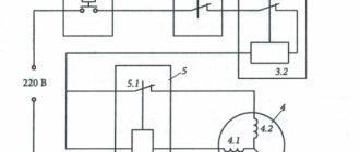
The diagram of a two-phase three-relay MTZ connection is shown in Figure 5.
Rice. 5. Scheme of two-phase three-relay connection of MTZ
The diagram shows:
- KA - current relay;
- KT - time relay;
- KL - intermediate relay;
- KH - indicator relay;
- YAT - trip coil;
- SQ - block contact that opens the circuit;
- TA - current transformer.
TDT-54 and TDT -60
0
Source:
To work in the forests of the Urals, Siberia and the Far East, more powerful skidders were required than the TDT-40. The Ministry of Automotive Industry instructed the designers of the Minsk Tractor Plant to develop a project for such a tractor in conjunction with the Scientific Research Autotractor Institute (NATI) according to the technical requirements of the Ministry of Forestry Industry of the USSR. Initially, the tractor was given the brand TDT-54. To increase productivity, a D-54 diesel engine with a power of 54 hp was used. tractor DT-54 of the Kharkov Tractor Plant. After the skidder TDT-54 received the go-ahead from the state commission for mass production, a detailed analysis of each unit was carried out. As a result, it was decided to modernize most of its components. In addition, the D-54 diesel engine was boosted to 60 hp. and as a result, the tractor received a new name TDT-60. In 1956, four of its prototypes passed all control state tests under production conditions at the Vakhtansky timber industry enterprise in the Gorky region. The simultaneous production of two tractors, MTZ-2 and TDT-40, completely different in design and purpose, put the plant in a difficult position. The plant did not have the opportunity to simultaneously develop two different productions: the production of the MTZ-2 tractor, which was extremely necessary for agriculture, and the TDT-40 tractor, in which the USSR Ministry of Forestry Industry was interested. Technical and economic calculations showed that the Minsk Plant needs to specialize in the production of wheeled universal row-crop agricultural tractors. The management of the plant submitted a proposal to the ministry - to stop production of the TDT-40 tractor at MTZ, transferring it to the plant in Karelia, and the developed TDT-60 model to the Altai Tractor Plant. By decree of the USSR government of January 30, 1956, the Onega Machine-Building Plant in Petrozavodsk was transferred to the Ministry of Tractor and Agricultural Engineering of the USSR for the production of TDT-40 tractors. Before that, it was under the jurisdiction of the USSR Ministry of Forestry Industry. In 1957, without stopping the production of TDT-40 at MTZ, the development of the tractor began at the Onega Tractor Plant. In total, until 1958, MTZ produced 12,977 TDT-40 tractors. In 1957, the TDT-60 tractor was put into serial production at the Altai Tractor Plant. This was the end of the history of skidders at MTZ, where for 7 years they were produced in parallel with wheeled ones.
Overcurrent protection time delay
To find it, the following calculation is carried out. The operating time of the first protection during a short circuit is determined:
T1=tп1+to1+tв1,
Where:
- T1 – required time,
- tп1 – shutter speed error,
- to1 – switch off time,
- tв1 – delay time for this relay.
The second protection will not work provided that the holding time for it is greater than T1, i.e. tв2>T1.
Tв2=Т1+tп2+tз,
Where:
- tп2 – error of the second relay,
- tз – spare time.
Thus, the stage will be equal to T=tв2-tв1=tп1+tо1+tп2+tз (for an independent time-current characteristic).
MTZ-5
0
Source:
Time passed, and with it the requirements for the manufactured MTZ-2 tractor grew. It had a low transport speed (13 km/h) and an insufficient number of gears. The tractor began to lag behind in terms of fuel efficiency and material consumption. It was necessary to increase the reliability and service life of the machine. Having summarized the experience of operating MTZ-2 tractors, taking into account the state and level of tractor manufacturing, the plant’s design team in 1955-1956. carried out work on a radical modernization of the machine. This made it possible not only to eliminate existing shortcomings, but also to expand the scope of application of the machine and improve technical and economic indicators. This is how new models of the Belarus tractor appeared: MTZ-5 (1956 model). MTZ-5M and MTZ-5L (samples of 1957). MTZ-5, possessing great versatility, had an independent power take-off shaft drive, a more powerful and economical engine, and a hydraulic linkage system with remote cylinders.
Differences from current cut-off
Logical bus protection
The MTZ uses time relays that make it possible to ignore voltage surges, which is impossible with cutoff (which is triggered not only during a short circuit episode, but also when the current increases of any other nature and duration). In addition, the use of the shut-off mechanism requires operator intervention to restore normal system operation. The relays themselves return to their original state when the cause of the opening is eliminated.
MTZ-5S
0
Source:
In 1959, after design improvements, production of the MTZ-5LS and MTZ-5MS tractors began. The letter “C” in the designation meant “high-speed”. Engine power was increased to 48 hp. (instead of 45) by increasing the speed to 1600 rpm (instead of 1500). The operating speed range was set within 5-10 km/h. The number of working gears in the gearbox was increased from four to five. Otherwise, there were no fundamental differences from the MTZ-5L and MTZ-5M tractors. Production of high-speed cars began in 1959.
Device and principle of operation
The principle of operation is that the current sensor (relay) is activated when the I setting is exceeded on the protected section of the line, after which, to ensure selectivity, the time relay is activated with a certain delay.
Where is it used? Maximum current protection is installed at the beginning of the line, that is, on the generator or transformer side of the supply substation.
Important! The MTZ coverage area lies between the power source (TP or generator) and the consumer (TP or other high-voltage equipment). Moreover, it is established from the source side, not the consumer side. But the zones of action of the steps can intersect with each other. For example, stage 1 often overlaps the coverage area of the second stage close to the disconnector, where Is are almost equal to the previous section of the line.
The protection response time delay is selected so that the first stage (on the supply transformer transformer) is triggered after the longest period of time, and each subsequent stage is faster than the previous one.
Interesting: the difference in the response time at the MTZ closest to the power source from the one next after it is called the selectivity stage.
Ensuring selectivity is important for uninterrupted power supply to as many electrical lines as possible. With its help, the disconnected part is reduced and localized in the area between the switching devices as close as possible to the damaged area.
At the same time, in the event of short-term self-correcting overloads associated with the start-up of powerful electric motors, the time delay and minimum voltage shutdown should ensure the supply of electricity to the network without shutting it down. At , the voltages decrease sharply, and when starting engines, such a drawdown usually does not occur.
The selection of current settings occurs according to the smallest Isk from the entire circuit, taking into account the operating characteristics of the connected equipment. This is again necessary so that the maximum current protection does not work when the electric motors self-start.
Overload can occur for three reasons:
- In case of single-phase ground fault.
- With a multiphase circuit.
- When the line is overloaded due to increased power consumption.
So, maximum current protection is necessary to prevent the destruction of power lines, cable cores and busbars at substations and electricity consumers, such as powerful 6 or 10 kV electric motors and other electrical installations.
MTZ-7
0
Source:
In 1958, the design was finalized, prototypes were made, tests were carried out, and drawings for the MTZ-7 all-terrain tractor with four driving wheels were issued in preparation for production. The first tractor design was developed using the front drive axle from the military all-terrain vehicle GAZ-67, did not have an adjustable track width of the front wheels and therefore did not provide for row-crop work. Due to the insufficient strength of the GAZ-67 bridge, the tractor did not pass the tests. The problem was solved after a GAZ-63 drive axle was installed on the tractor. The production of cabins for Belarus tractors began. The design of the removable cabin made it possible to use it on the tractor completely closed and in the form of an awning. With the use of such a cabin, the working conditions of the tractor driver have significantly improved.
Types of overcurrent protection
In electrical networks, 4 types of overcurrent protection are used. Their use is dictated by the conditions that need to be created for reliable operation of electrical equipment.
MTZ with current-independent time delay
In such devices, the time delay does not change. To set the settings for a period sufficient to activate relays with independent characteristics, selectivity stages are taken into account. Each subsequent shutter speed (towards the current source) increases from the previous one by a period of time corresponding to the selectivity stage. That is, during calculations it is necessary to comply with selectivity conditions.
Overcurrent protection with current-dependent time delay
In this protection, the process of setting the overcurrent protection settings requires more complex calculations. Dependent characteristics, in cases with induction relays, are selected according to the IEC standard: tсз = A / (kn - 1), where A, n are sensitivity coefficients , k = Iwork / Iaver - current multiplicity.
It follows from the formula that the time delay is no longer a constant. It depends on several parameters, including the strength of the current entering the relay windings, and this dependence is inverse. However, the shutter speed is not linear; its characteristic approaches hyperbole (Fig. 3). Such MTZ are used to protect against dangerous overloads.
Figure 3. Characteristics of MTZ with dependent time delay
MTZ with limited current-dependent time delay
Devices of this type of relay protection combine two stages of protection: a dependent part with a hyperbolic characteristic and an independent one. It is noteworthy that the time-current characteristic of the independent part is direct, smoothly conjugate with the hyperbola. At small multiples of critical currents, the dependent period characteristic is steeper, and at large multiples, the curve is flat (used to protect high-power electric motors).
MTZ with start (blocking) from a minimum voltage relay
In this type of differential protection, a combination of overcurrent protection is used using the influence of minimum voltage. In an electromechanical relay, the contacts will open only when the increase in current in the network leads to a drop in the potential difference. If the drop exceeds the lower limit of the set voltage, this will trigger the protection. Since the setting is set for a voltage drop, the relay will not respond to sudden surges in current in the network.
MTZ-50
0
Source:
Until 1959, MTZ had the capacity to produce only 18,000 wheeled tractors of the MTZ-2 type, 6,000 TDT-40 tracked skidders and 40,000 D-40 engines. Serial production of the MTZ-5, MTZ-5M, MTZ-5L tractors was still underway, work was carried out to modernize them, and in 1956 the designers basically designed a new diesel engine for the future MTZ-50 tractor. There was great interest in the creation of a new promising row-crop tractor not only at the plant, but also in the country. The technical design of the tractor was completed in 1957 and approved by the Main Scientific Automotive and Tractor Institute. In 1958, the experimental workshop produced several prototypes of the tractor. Based on the test results, the scientific and technical council of the VO "Soyuzselkhoztekhnika" recommended the wheeled universal row-crop tractor class 1.4 "Belarus" MTZ-50 for mass production. The MTZ-50 tractor was equipped with a 55 hp diesel engine, the weight of the machine was reduced by more than 400 kg. The tractor transmission was equipped with a 9-speed gearbox, providing a speed range ranging from 1.65 to 25 km/h.
MTZ-52
0
Source:
In 1959, based on the results of state tests, the design of the MTZ-50 tractor was finalized, the necessary documentation was issued and put into preparation for production. Based on the MTZ-50 tractor, a modification of the all-terrain tractor with four driving wheels, the MTZ-52, was developed. Due to lower slipping losses, the fuel efficiency of the MTZ-52 tractor is higher at all operating limits than the MTZ-50 tractor. On November 14, 1959, the Council of Ministers of the USSR issued a resolution “On the organization of specialized production of wheeled tractors, motorcycles and engines for them at enterprises of the BSSR.” One of the points of the document stated: 2. Oblige the Council of Ministers of the BSSR to ensure: c) the production of Belarus MTZ-50 tractors starting in 1961 and MTZ-52 tractors starting in 1962, increasing the production of tractors of these brands to 75,000 units in 1965 year. The Council of the National Economy of the BSSR, by its decision of December 19, 1961, decided: 3. For a non-stop transition to a new tractor model, provide for the phased introduction of the MTZ-50 tractor, for which: - approve the transition model MTZ-50 tractor for production at MTZ for 1961-1962 PL on the chassis of the MTZ-50 tractor with a serial D-48 PL engine, boosted to 50 hp. - production of MTZ-50 tractors with the D-50 engine will begin in the fourth quarter of 1962. 1960 The plant is under reconstruction. New equipment was installed in the workshops and outdated equipment was replaced. The design of the MTZ-50 tractor was finalized, the necessary documentation was issued and put into preparation for production. Based on the MTZ-50 tractor, the plant's design team developed a modification of the high-cross-country tractor with four driving wheels MTZ-52. This machine complemented the basic model and expanded its scope of application in agricultural and transport work, especially in conditions of high soil moisture.
Calculation of current overcurrent protection
The stability of operation and reliability of operation of overcurrent protection depends on the settings of the operating current parameters. Calculations should ensure guaranteed operation of the relay in case of emergency, but its operation should not be affected by the parameters of the load current, as well as short-term surges that occur during engine starting mode.
It should be remembered that overly sensitive relays can cause false alarms. On the other hand, underestimated response parameters cannot guarantee the safe, stable operation of electrical appliances. Therefore, when calculating settings, it is necessary to choose a golden mean.
There is a formula for calculating the average current value to which an electromagnetic relay reacts [ ]:
Is.z. >In. Max.,
where I s.z. – the minimum primary current to which the protection must respond, and I n. max . – limit value of load current.
The relay return current is selected in such a way that it is sufficient to re-close the contacts in the used device. To determine it we use the formula:
I in = kn.×kz.×Iwork. Max.
Here I in – return current, k n . – reliability coefficient, k з – self-starting coefficient, I slave. max . – the value of the maximum operating current.
In order to bring the return and operation currents as close as possible, a return coefficient is introduced, calculated by the formula:
kв = I in / I s.z. taking into account which Iс.з. = kn.×kz.×Iwork. Max. /kv
Ideally, kв = 1, but in practice this coefficient is always less than one. The higher the value of kv, the higher the sensitivity of protection. Hence the conclusion: to increase sensitivity, it is necessary to select kv in a range tending to 1.
MTZ-50X
0
Source:
In 1963, the design development was completed and prototypes of the MTZ-50 cotton-growing tractor were produced. The tractor is designed for cultivating and harvesting cotton in a four-row machine system with a row spacing of 90 cm. The MTZ-50X tractor was fundamentally different from the MTZ-50 tractor in the design of the front axle - it had one guide wheel. The final drive assembly with additional gearboxes was also changed. All necessary tests of the tractor were completed in 1966, after which preparations began for its mass production by factory services. Production of the MTZ-50X tractor lasted eight years: from 1969 to 1977. Then production was transferred to the Tashkent Tractor Plant.
Three tracked modifications were created on the basis of the MTZ-50 tractor, and the unit unification with the MTZ-50 tractor was more than 62%. Tracked modifications were unified by 95-98%. In 1967, a version of the T-54V tracked tractor was put into production in two modifications: T-54V-S1 with a track width of 950 mm for cultivating vineyards with row spacing of 1.8 m or more, and T-54V-S2 with a track width of 85- mm for cultivating vineyards with row spacing of 1.5 m. In 1968, production of the T-54L tractor began.
Operating principle
MTZ is a type of power network protection mechanism using a relay, used when there is a threat of a short circuit on a certain section of the electrical circuit.
The operating principle of overcurrent protection is quite similar to that of the cut-off mechanism. If, when using the latter, the current is cut off immediately, then when using MTZ, the shutdown occurs after a certain period of time. It's called time delay. The value it takes is determined by the proximity of the incident to the food provider. The further away the segment is, the lower the number. The value by which the indicator of the nearby section differs from that of the remote section (selectivity level) describes the period after which the protection is activated in the near section (disabling the far section as well), if it was not activated in the distant section where the short circuit incident occurred.
Important! The step indicator must be kept small so that the system has time to turn on before the incident causes serious damage to the electrical network.
MTZ-80
0
Source:
In 1966, Decree of the Council of Ministers of the USSR No. 606 was issued on the creation of a universal row-crop tractor with a power of 75-80 hp. traction class 1.4. The designers created such a tractor by modernizing the MTZ-50 tractor, assigning it the MTZ-80/82 brand. In addition to increasing the power of the serial engine, a significant number of improvements were made to the design of this tractor. In 1972, state tests of the MTZ-80/80L tractor (with electric starter and starting engine) were completed. Tests have shown that the number of machines and implements mounted with the tractor has increased to 230 items. High speed (up to 35 km/h) made it possible to use the tractor more efficiently for transport work. In 1974, the plant began serial production of the MTZ-80. The tractor was conceived as a base one, taking into account the development of a new family of unified energy-rich tractors, both wheeled and tracked. The main differences between the MTZ-80 tractor and the MTZ-50 tractor were the following: A reduction gearbox was installed in the gearbox, doubling the number of gears - 18 forward gears and 4 reverse gears; Damping springs were introduced into the clutch coupling, the design of the flywheel was changed - it became flat, which improved ventilation of the entire clutch compartment and cleaning the cavity from wear products of rubbing surfaces; A creeper has been introduced - a gear reducer, which expands the speed range of the tractor. Its use allowed the tractor to move at speeds of up to 1.3 km/h; The automatic differential lock of the rear axle has also undergone changes. Now the blocking could be carried out while the tractor was moving; A change in the design of the rear PTO drive made it possible to obtain two rotation speeds instead of one; The hydraulic suspension system has also been modernized. It is equipped with a hydraulic adhesion weight increaser (GSV), a force and position regulator. The system's load capacity has been increased to 2000 kg (instead of 1500) by increasing the pressure in the system from 130 to 160 kg/cm2; The Minsk Motor Plant was involved in modernizing the engine. The engine had two modifications with electric start. The crankshaft speed was raised to 2200 rpm.
Full range of tractors "BELARUS" MTZ
The manufacturer produces a wide range of special-purpose equipment to order, so we will consider only mass-produced models.
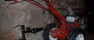
- Mini tractors and walk-behind tractors - MTZ-132N, MTZ-152 and MTZ-09N. Power is 9 HP for walk-behind tractors and 13 HP for mini-tractors. Equipped with GX390 gasoline engines (Honda). Designed to perform small mechanized work on soil cultivation and transportation of goods in small private farms, on small farms;
- The MTZ-320 series is seven compact vehicles with diesel engines of 33-36 HP. Models 320.4, 320.4M and 320.5 come with enclosed all-weather cabs. Equipped with domestic or Italian power units LOMBARDINI LDW1603/B3, belong to traction class 0.6;
- MTZ-422 series - two main modifications 422 and 422.1 with a power of Lombardini LDW 2204 engines equal to 50 HP and meet the high environmental standard Euro-3A. Suitable for use in agriculture, housing and communal services;
- MTZ-550 is a large subgroup of basic and special machines with power units up to 90 HP. All tractors use domestically produced diesel engines;
- BELARUS-622 – traction class 0.9, environmental class Tier 3A. Adapted for export, widely used in housing and communal services and the agricultural sector;
- MTZ-80.1 is a large subgroup of 21 tractor models with a traction class of up to 1.4. Engine power reaches 95 HP, wheel arrangement is 4×4, Bosch injection systems, load capacity on the suspension axle is up to 4 tons. These are cars with improved performance characteristics, a high level of comfort and safety;
- BELARUS-921 is a tractor with a diesel engine and a turbine, power 95 HP, torque 464 N/m. Ecological class Stage II. Cabin of increased comfort;
- BELARUS-1025 – machines with a power of up to 110 HP, used primarily in agriculture. They can be combined with various types of passive and active hitches, and the hydraulic system capacity reaches 56 liters per minute. Submodels are available with all-weather cabins or tent frames;
- Series 1221 – basic model with a power of 123 HP. Second traction class, all-wheel drive, load capacity up to 4300 kg. A universal machine for agriculture, housing and communal services, and the construction industry;
- MTZ-1502 is a caterpillar tractor with a 158 HP engine. Widely used in reclamation activities, construction and other fields. Another tracked vehicle is MTZ-2103. Power 212 HP. Designed for work on viscous, loose soils;
- MTZ-1523 - wheeled tractors with all-wheel drive, power 148 HP, load capacity up to 6.5 tons. The machines are capable of working with wide-cut agricultural implements, for example, large balers or combine harvesters;
- MTZ-2022 – traction class 3-4, power 212 HP. Compatible with any trailed and mounted implements. Torque up to 900 N/m, specific fuel consumption only 250 g/kW/h. Maximum control ergonomics, climate control;
- BELARUS-3022DV is a heavy agricultural machine with a 303 HP engine. Transmission – 36 forward and 24 reverse gears. The hydraulic system capacity is 120 liters per minute. Load capacity on the rear axle of the suspension is 10 tons. The model is intended for large agro-industrial enterprises;
- MTZ-3522 is a machine with even greater power equal to 355 HP. The hydraulic pump capacity is up to 160 liters per minute. The model can work simultaneously with combined front and rear wide-cut units;
- MTZ-4522 is an eighth traction class vehicle with a 466 HP engine (American Caterpillar C13 ACERT). It is produced in limited quantities for export, since only a few enterprises have a need for such equipment.
Each series includes basic models that can be optionally equipped with various systems, for example, air conditioners, creepers, ballast wheel weights, etc. The choice and specific equipment depend on the tasks assigned, the specifics and scale of the work.