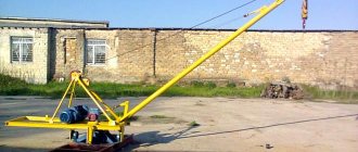
Various lifting devices are an integral attribute of any construction. Many scientists believe that even the ancient pyramids in Egypt were built using special lifts. True, their design remains a mystery. But the device of a small jib crane called Pioneer, which will be discussed today, is known to every builder with experience.
Lifts (jib cranes) Pioneer: technical characteristics, device, photo
Various lifting devices are an integral attribute of any construction. Many scientists believe that even the ancient pyramids in Egypt were built using special lifts. True, their design remains a mystery. But the device of a small jib crane called Pioneer, which will be discussed today, is known to every builder with experience.
This unit is lightweight and highly mobile. It assembles and disassembles simply and quickly. It can even be brought to the site in a Gazelle, the work done, and then disassembled and taken away. Moreover, it is quite possible to install the crane on the ground, in a pit, on the roof, as well as on building floors.
Pioneer lifts are made by many enterprises specializing in the production of all kinds of lifting equipment. We can mention the domestic one, Impulse LLC from Kirov, PKF Chelny Crane Company LLC.
There are three main modifications of the crane, the lifting capacity of which can be, respectively, 0.5, 0.75 and 1 ton (this is the maximum). The boom can be solid or collapsible, and the supporting frame, which serves as the base of the unit, can be equipped with wheels or have a stationary design.
Application
This jib crane is capable of moving any objects, working intensively in heat of forty degrees and in frosts down to minus forty. It will easily deliver building materials, installation structures, currently needed equipment, tools and inventory to the roof, as well as to any of the floors.
During roofing work, a unit equipped with a convenient rotating boom will help to quickly supply the required volume of mastic, rolled roofing or insulating material to the roof.
At manufacturing enterprises, the Pioneer crane is often used for carrying out repair work, as well as for quickly loading and unloading any materials, machines, and metal structures.
Photo of Pioneer type lift
The Pioneer type lift is used by trade enterprises, as well as wholesale warehouses. The lift will help to quickly ship heavy rolls of linoleum, pallets with ceramic tiles, and various lumber to the buyer.
Advantages and disadvantages
Advantages:
- Simple and extremely reliable design, ease of use.
- The speed of assembly and disassembly is no more than half an hour.
- High mobility, which allows the crane to be used even at distant sites.
- There is no need to register the lift with Rostekhnadzor.
- There is no need to make a pit before work, and no anchors are required during installation.
The boom's 360-degree rotation makes lifting and lowering loads easy.
- Low cost, low energy consumption.
Flaws:
- Flexibly suspended cargo does not always create comfortable and safe conditions.
- The maximum weight that the crane can lift is from 500 to 1000 kilograms (depending on the modification).
Device
The design of this collapsible mechanism is extremely simple. The crane consists of the following elements:
- The main supporting frame (dismountable, bolted, can stand on wheels), on which the second frame is mounted - a rotating one.
- Safety guy ropes, cargo rope, counterweight, electric drive.
- A rotating boom (which can be solid or collapsible, bolted), equipped with a jib.
- The final stop mechanism (which is located at the end of the boom), the limit switch (it is installed on the lifting mechanism).
Scheme of Piner type lifts
Principle of operation
The load that needs to be lifted must be hooked onto the crane hook or placed on a special platform cradle (it is not included in the unit package, but must be purchased separately). The load is lifted by operating an electric winch through a block installed on the turning unit. A remote control with buttons is used to make control easier.
Technical characteristics of Pioneer lifts are presented in the table:
| Characteristics | Unit measurements | KP 500 | KP 750 | KP 1000 |
| Boom extension | m | 2,5 | 2,5 | from 2.5 to 4 |
| Load capacity at boom extension 2.5 m | T | 0,5 | 0,75 | 1 |
| Load capacity at boom extension 3 m | T | — | — | 0,8 |
| Load capacity at boom extension 4 m | T | — | — | 0,5 |
| Lifting height at boom extension 2.5 m | m | 4,5 | 4,5 | 6,2 |
| Lifting height at boom extension 3 m | m | — | — | 6 |
| Lifting height at boom extension 4 m | m | — | — | 5,3 |
| Lifting height (from floor) | m | up to 50 | up to 45 | up to 50 |
| Working speed | m/min | 16,8 | 8,4 | 11,8 |
| Platform rotation amount | degree | 360 | ||
| Electric drive power | W | 4000 | 4000 | 4750 |
| Lifting mechanism | electric | |||
| Mains voltage | IN | 380 | ||
| Rotary mechanism type | manual | electric | ||
| Number of counterweights | PC. | 9 | 9 | 15 |
| Weight (total) | T | 1,345 | 1,355 | 1,82 |
| Rope thickness | cm | 0,69 | 0,69 | 0,78 |
| Dimensions | m | 4.2x1.7x5.4 | 4.2x2.0x5.4 | 6.1x2.14x6.5 |
| Width (transport) | m | 1,77 | 2,18 | 2,135 |
| Length (transport) | m | 2,45 | 2,67 | 2,85 |
| Height (transport) | m | 1,325 | 1,35 | 1,6 |
| Boom type | L-5200 | L-5200 | L-6450 | |
| Boom thickness | cm | 10,2 | 10,2 | 13,3 |
The video shows the Pioneer lift in action:
Source: https://allspectech.com/stroitelnaya/podemniki/gruzovye/pioner.html
Pioneer lifts - light and mobile equipment
Various lifting devices are an integral attribute of any construction. Many scientists believe that even the ancient pyramids in Egypt were built using special lifts. True, their design remains a mystery. But the device of a small jib crane called Pioneer, which will be discussed today, is known to every builder with experience.
Pioneer crane, lifting capacity 500, 750 and 1000 kg – sale, spare parts
The Anix trading house offers for sale reliable, safe, maneuverable Pioneer cranes of various lifting capacities. If you are interested in high quality combined with affordable prices, contact us!
Crane Pioneer capacity 1000 kg
Crane Pioneer lifting capacity 500 and 750 kg
The Pioneer crane allows you to lift a load to a height of up to 6 m (for the Pioneer model 1000 kg, for the Pioneer 500 kg and 750 kg models the height is 4.5 m), if you install the equipment on the roof of a building, the height can reach 50 meters. Depending on the model, Pioneer cranes can have different lifting capacities. The most popular models today are Pioneer 500 kg and Pioneer 1000 kg. You can find models with a load capacity of 750 kg.
Pioneer cranes 500 kg, 750 kg, 1000 kg have a large number of operational advantages. Convenient transportation of special equipment is ensured by the possibility of disassembly.
Also among the advantages of the models is the reliability and ease of operation of the system, low cost and minimal maintenance costs.
In addition, no special training is required to operate the equipment.
Specifications:
Address and hours
WORKS
Monday Friday
8:00–18:00
Saturday
10:00–16:00
Fill out this form:
Find out prices
Diagram of the Pioneer crane with a lifting capacity of 500 kg
In our company, the Pioneer crane is presented in various modifications. For example, the Pioneer 500 kg crane is made in two configurations: the boom can be regular or collapsible. The Pioneer crane 1000 kg may have wheels, or it may be an adjustable model.
In any case, the design of the model includes a support frame, a turntable with a winch, a boom and a special coupler for it, automation, an engine, a cable, a counterweight, and a hook for coupling the load. Depending on the height to which the load needs to be lifted, special equipment can be installed either on the roof/floor or on the ground.
In the first case, the lifting height can reach 50 m. If the crane is standing on the ground, then the Pioneer 1000 kg model is capable of lifting a load to a height of up to 6 m, the Pioneer 500 kg and 750 kg models - up to 4.5 m. Welded metal is used in the production of the base frame on which the king pin is mounted, moving with the help of rolling bearings.
On the platform there is an engine, a winch, and counterweights - the platform is attached to the kingpin using a wedge bushing. The Pioneer crane is equipped with a well-functioning safety system, ensured by the use of limit switches and limiters that fix the position of the hook, eliminating the risk of the load falling off.
The simplicity and reliability of the Pioneer crane allows you to work with it without prior preparation. In addition, the operation of Pioneer cranes 500 kg, 750 kg, 1000 kg does not require any major investments - no expensive repairs, no consumables, spare parts, and so on.
The simplicity and efficiency of all operations is ensured by the operation of an electric drive, consisting of a motor, gearbox and winch. The Pioneer 500 kg and 750 kg cranes require manual boom rotation (a swing lever is used), but the Pioneer 1000 kg model is equipped with an electric boom rotation function, as well as a function for changing the boom angle - this increases the boom reach, but the load capacity decreases.
Why is it profitable to buy jib and jib cranes in Moscow from us?
"Art-Podyom" is a direct manufacturer of special equipment, so you get the best combination of cost and quality. It is possible to produce models of non-standard jib and jib cranes with technical characteristics for a specific customer. Cooperation with us will be beneficial for the following reasons:
- Crane equipment is manufactured in accordance with current SNIPs and GOSTs.
- Jib and jib cranes are safe to use if safety regulations are followed.
- It is possible to install and dismantle at the customer's site.
- Special equipment is covered by an official warranty, within the framework of which defects and malfunctions are eliminated.
- There is delivery in Moscow and the region by transport companies, in Russia by carrier companies.
To buy jib or jib cranes from our company in Moscow, contact the managers of the online store. Specialists will give detailed advice on the parameters and operation of the equipment, complete the purchase, accept payment, and organize delivery throughout Russia.
Portable lightweight cranes
Light weight, the ability to assemble the crane and disassemble it into sections, which can be delivered to hard-to-reach places on a construction site, make the crane a good assistant when lifting building materials.
The cantilever-beam crane (Fig. 5.6.1) is designed for lifting and supplying various building materials into the building through door and window openings.
Rice. 5.6.1 Portable lightweight jib crane
The crane consists of a vertical telescopic tubular stand 5 with support shoes 1 and 6, a beam boom 9 with a load carriage 8, mechanisms for moving the carriage and lifting the load. The telescopic stand allows the crane to be installed in rooms of varying heights.
It is made of two sections: the main (fixed) and retractable. A beam boom is pivotally attached to the main section of the rack, held in working position by rigid rods 7. A load carriage 8 moves along the lower shelves of the boom on support rollers.
The mechanism for moving the carriage consists of a traction rope 4, guide blocks and a manual winch 3. The traction rope, wound onto the winch drum, goes around the guide blocks and is attached to the carriage on opposite sides with two free ends.
By rotating the drive handle, the carriage is moved along the boom.
The mechanism for lifting loads consists of a reversible worm winch 2 with control devices, a cargo rope and a hook clip 10. One end of the cargo rope is attached to the winch drum, the second goes around the blocks of the stand, carriage, hook clip and is attached to the boom head.
The maximum lifting capacity of cantilever girder cranes is 0.1-0.2t, the boom reach is up to 3 m, the rope capacity of the drum is 40-70 m. KOR-200 crane (photo 5.6.1).
Photo 5.6.1 Crane KOR - 200 Saratov. Window crane KOR-200 with an electric winch TL-12B, designed for operation in a non-explosive environment. The tap is installed in the window opening. Lifting and lowering construction loads weighing 200 kg. The KOR-200 crane is controlled by a pendant push-button remote control. Does not require counterweights.
Technical characteristics of the KOR-200 crane
| Load capacity, kg | 200 |
| Lifting height, m | 200 |
| Angle of rotation relative to the vertical axis relative to the initial (average) position, degrees. | 100 |
| Lifting speed, m/sec | 0,24 |
| Maximum boom radius, mm | 1260 |
| Control method: | using the control station |
| Crane weight without winch, kg | 45 |
| Power V; frequency Hz | 220 / 380; 50 |
Jib crane
The maximum lifting capacity of cantilever beam cranes of the Pioneer type is 0.5t-1t, boom radius up to 3 m, drum rope capacity 40-70 m. Jib full-rotary portable crane (Fig. 5.6.2)
Rice. 5.6.2 Jib full-rotation portable crane
The crane consists of a base with a skid 1, a rotating platform 3, a tubular boom 9, a load lifting mechanism and a control system. A tubular glass 10 is installed in the center of the base, into which the pivot of the turntable is inserted. A cargo winch 5 and a counterweight 2 are located on the turntable console.
A tubular boom is hinged to the rotating platform at the front and is held in working position by guys 4. The boom reach is changed by changing the length of the guys. The load lifting mechanism consists of a reversible worm winch 5 with control devices, a cargo rope 6 and a hook holder 8.
The load rope from the winch drum passes through the boom head block, the hook cage block and is secured to the boom. A lever limiter 7 of the hook lifting height is installed on the boom head, which turns off the winch motor when the hook cage approaches the uppermost position.
Rotation of the platform and movement of the crane are done manually. Photo 5.6.2 of the Pioneer crane.
Photo 5.6.2 Jib-beam crane KP-1000 “Pioneer”
Technical characteristics of the Pioneer crane
| Load capacity, kg | 500 | 750 | 1000 |
| when installed on the ground, m | 4,5 | 4,5 | 6 |
| when installed on the ceiling, m | up to 50 | up to 50 | |
| Lifting speed, m/s | 0.2 to 50(100) | 0,14 | 0,74 |
| Drive power, kW | 4,0 | 4,0 | 4.25 |
| Overall dimensions, m | 4.2 x 1.78 x 5.4 | 4.28 x1.7x5.4 | 4.5 x 2.0 x 6.0 |
| Weight without c/g, kg | 480 | 480 | 900 |
| Total weight, kg | 910 | 921 | 1790 |
| Rope diameter, mm | 6,9 | 6,9 | 12 |
Source: https://www.armohim.ru/legkie-krany.html
DIY crane
The design of a homemade crane will help those who themselves build a residential building, a summer house or a garden house.
A homemade crane will make it easier to install foundations, walls, ceilings and other structural elements.
Using such a jib crane, you can carry a load over a distance of up to 3 m, lift it to a height of up to 2 m and lower it to a depth of 2.5 m. The mechanism should be designed to install structures weighing up to 300 kg.
Rice. 1. Diagram of a crane that you can make yourself:
1 - block, 2 - crane boom, 3 - crane trolley, 4 - telescopic stand, 5 - paired angles, 6 - boom base blocks, 7 - I-beam, 8 - struts, 9 - crane trolley moving winch, 10 - load frame , 11 – lifting mechanism winch, 12 – electric winch drive, 13 – stand corner, 14.15 – M 16 bolts, 16 – lifting hook assembled with a block.
The crane consists of a horizontal boom beam (the crane trolley moves along it) and vertical support posts made of steel pipes, to which horizontal beams are attached. The crane is collapsible, which allows you to move it from place to place.
Construction of crane stands.
They are made of pipes with a diameter of 140 mm. Their height can be increased up to 3 m using telescopic incoming pipes. To prevent the posts from sinking into the ground, corners are welded to the base. A horizontal beam is welded to the top of the supports - two corners x 65 x 10 mm connected together. A horizontal guide is attached to it from below with four bolts - an I-beam No. 20, having dimensions of 200 x 100 x 5.2 mm, 3000 mm long, along which the crane trolley moves.
The second pair of guide supports consists of two vertical pipes connected at the top and bottom. For greater stability, two inclined supports are welded to them, which in turn connect the racks with a rectangular frame. The latter prevents the crane from tipping over, as it serves as a base for laying sandbags or concrete blocks.
An important feature of a jib crane is its control. Those who will build and operate it need to know: the crane has a lifting and moving device. If necessary, any part can be lowered below the zero mark (into a pit or trench). The entire system of cables and pulleys of the lifting device is driven by an electric motor. The trolley is moved by a hand winch using a cable. One end of it is fixed to the trolley, then the cable goes through the block to the drum, makes five turns and, again passed through the blocks at the base and at the end of the boom, is fixed to the crane trolley.
The hook is lifted by a cable, fixed at one end to the winch and passing successively through the blocks of the base, boom and crane trolley, then the cable lowers down, forms a loop on which the block with the hook is suspended, and through the block of the crane trolley is fixed at the end of the boom.
Rice. 2. Diagram of the mechanism for lifting and moving the load:
1 - boom end block, 2 - cable fastening pin on the crane trolley, 3 - boom base blocks of the crane trolley moving mechanism, 4 - cable moving the crane trolley, 5 - drum, 6 - hoisting mechanism winch, 7 - hoisting mechanism boom base block , 8 – blocks of the maroon trolley, 9 – hook block, 10 – lifting rope fastening unit.
The lifting device can also be driven by a conventional manual winch, which will provide the crane with complete autonomy.
Before starting work, you should carefully check the strength of the nodes and supports. Standing under the boom is not allowed - this is the basic safety rule at any construction site.
We hope that there will be farmers and gardeners who will build a crane to make their work easier. Maybe not like that. But similar. The main thing is that he helps in the work.
Crane Pioneer
Crane lifting capacity 500; 1000 and 2000 kg.
Collapsible (very convenient when moving the crane from one construction site to another, as well as installing the crane at the work site) or non-collapsible boom. Can be manufactured with manual or electric rotation.
Manual rotation of the platform - the operator or his assistant turns the crane by hand on the rotating platform in the desired direction. Electric platform rotation - the operator controls it from the remote control (custom made).
With a counterweight or with a platform for building materials (brick blocks, etc.)
e) The cranes of the PIONEER-500 and PIONEER-1000 types from Lenstal LLC are equipped with imported components, so there are no repair issues.
The PIONEER crane has some attractive feature: reliability, which in any construction will be the main criterion when choosing a crane!
Thanks to its compact size and dimensions (movement even in narrow corridors), the crane can be moved by 2-3 installers.
Methods for attaching a rope to a lifting mechanism
When creating complex pulley blocks, there are often situations when a cable of the required length for attaching the moving block is not at hand.
Crane for gas blocks
Methods for attaching a cable using general-purpose rigging:
- Using a cord. Using a self-tightening knot, the cord is tied to the main cable. As the load is lifted, the grappling knot moves along the main rope, thereby allowing the height of the load to be increased.
- Using clamps. In the case of using a steel cable, it is not possible to use a cord, so it is necessary to use special clamps.
Production of Pioneer crane 500, 1000, 2000 kg
Pioneer construction jib cranes are used for loading and unloading operations and for construction and installation operations. Cranes are installed both on the ground and on buildings, placing the equipment on the floor slabs of structures. By lifting capacity cranes
Pioneer cranes are divided into 500, 1000 and 2000 kilograms. Pioneer cranes can also be equipped with wheels for movement. It is important to know that the crane can only be moved without a load. Each crane is equipped with a counterweight made of reinforced concrete slabs. The angle of the boom is adjusted using grooves and is attached to the spindle. The crane is transported disassembled.
Buy a Pioneer crane at manufacturer's price
Our company invites you to order a Pioneer construction crane with a lifting capacity of 500, 1000 and 2000 kg. directly from the manufacturer. At the request of the customer, additional equipment with the necessary equipment is possible. As a rule, cranes are shipped from stock, if upon request the crane is not in stock, the production time is about 10-15 working days.
Characteristics of the Pioneer Crane 500 kg.
| Boom radius, meters. | Loading capacity, double rope reeving, tons. |
| reach 4.0 m. | 0,3 |
| offset 2.0;2.5;3.0; m. | 0,5 |
| Hook lifting height, m: | up to 4.5 |
| Hook lowering depth, double reeving, meters. | 50 |
| Support contour, mm. | 1650x1650 |
| Radius of the turning part, mm. | 2050 |
| Load lifting (lowering) speed | |
| double reeving, m/min. | from 10.5 |
| single reeving, m/min. | from 21 |
| angle of rotation of the turning part, degrees. | 360 |
| swing mechanism drive | manual |
| Crane weight, kg. | 450 |
| Counterweight mass, kg. | 580 |
Characteristics of the Pioneer crane 1000 kg.
| Boom radius, meters. | Loading capacity, double rope reeving, tons. |
| reach 2.4 m. | 1 |
| reach 3.3 m. | 0,75 |
| reach 4.4 m. | 0,4 |
| Hook lifting height, m: | |
| reach 2.4 m. | 5,7±0,2 |
| reach 3.3 m. | 5,35±0,2 |
| reach 4.4 m. | 4,5±0,2 |
| Depth of lowering the hook, double reeving meters. | 50 |
| Departure, m.: | 4,4±0,1 |
| Support contour, m. | 2.0x2.0 |
| Radius of the turning part, mm. | 1780 |
| Load lifting (lowering) speed: | |
| double reeving, m/min. | 22,2 |
| single reeving, m/min. | 44,4 |
| turning speed rpm | 1±0,2 |
| angle of rotation of the turning part, degrees. | 360 |
| Crane weight, tons | 0,91 |
| Counterweight weight, tons | 0,89 |
Characteristics of the Pioneer crane 2000 kg.
| Boom radius, meters. | Loading capacity, double rope reeving, tons. |
| reach 4.6 m. | 1,5 |
| reach 4.4 m. | 1,7 |
| reach 4.1 m. | 2 |
| Hook lifting height, m: | |
| reach 4.6 m. | 4,3±0,2 |
| reach 4.3 m. | 4,5±0,2 |
| reach 4.1 m. | 4,65±0,2 |
| Hook lowering depth, double reeving, meters. | 100 |
| Reach, meters: | 4,6±0,1 |
| Support contour, m. | 3.2x3.2 |
| Radius of the turning part, mm. | 3000 |
| Speed of lifting (lowering) the load. | |
| double reeving, m/min. | 5,6 |
| single reeving, m/min. | 11,3 |
| turning speed rpm | 1>0,2 |
| angle of rotation of the turning part, degrees. | 360 |
| Crane weight, tons. | 1,5 |
| Counterweight weight, tons. | 2 |
Source: https://kran-balki.ru/index.php/kran-pioner
Characteristics:
request has been sent
Your request has been sent. Our manager will contact you soon!
The KPM Pioneer crane is designed for lifting loads and installing it on the ground and floors of buildings and structures.
The crane is a collapsible structure, convenient for transportation and installation. For ease of transportation, upon request, it is supplied with a collapsible boom. The length of the boom element does not exceed 3.5 m.
Specifications
depending on boom inclination
Rope diameter, mm
Hodovitsa with a rotating frame, mm.
The Pioneer crane is an indispensable mechanism in the case of construction or repair and construction work that involves lifting and moving various cargoes. Installation of this unit is carried out with ease on the ground, as well as on the floor areas of structures and buildings.
Features of the KPM Pioneer jib crane
Cranes of this type have a lifting capacity of no more than one ton. At the same time, the operating costs of this unit are minimized. The model is quite compact. The crane is easy to assemble and operate. The minimum counterweight weight is 750 kilograms.
The Pioneer crane is effectively operated in the case of a temperature regime of 40/+40 degrees. Thanks to this, the unit can be used in open production areas throughout the year. In this case, the air humidity should be no more than eighty percent. The wind speed should be no more than 12 meters per second.
Main characteristics of the Pioneer crane KPM
Installed on the ground at zero level, this unit is capable of lifting loads:
- to a height of up to 4.5 meters with a load capacity of 500 kg and 750 kg;
- to a height of up to 6 meters with a load capacity of 1000 kg.
As a rule, a crane is installed on the roof of buildings under construction or completed to carry out roofing work related to lifting and lowering materials. Units with a load capacity of 500 and 750 kilograms are equipped with a mechanical rotation of 380 degrees. Units with a lifting capacity of 1000 kilograms are equipped with an electric drive, thanks to which control of the rotating part of the crane is quick and easy.
The Pioneer crane with a lifting capacity of 500 kilograms is produced in two versions:
- A whole arrow with a length of 5.2 meters and a diameter of 102 millimeters.
- A collapsible bolted boom with a length of 5.2 meters and a diameter of 102 millimeters. The bolted connection makes it easy to transport the equipment.
The Pioneer crane with a lifting capacity of 1000 kilograms is produced in two versions:
- on wheels;
- without wheelbase (adjustable version).
The model with a lifting capacity of one ton has three boom positions:
As the boom reach increases, the lifting capacity becomes smaller. From the ground, the lifting height is six meters.
KP-500K (version 1) - search kit
- Is a modification of KP-500KSearch kit KP-500K comprises generator GP-500K And receiver PP-500K, and is designed to search for places of damage, determine the route and depth of the cable using induction and acoustic methods.
Generator GP-500K used to create a signal current in communications when searching for traces and faults using the inductive method.The PP-500K receiver is used when searching for communication routes and fault locations using the active (with generator) or passive induction method and searching for faults using the acoustic method.
The search kit KP-500K is sold in three versions:
Purpose of the search kit KP-500K (version 1):
- High-precision determination of fault locations in underground cables using induction, acoustic and potential methods;
- Inspection of the area and search for the route of communications, including live ones (cable lines, pipelines);
- Determination of the depth of underground communications;
- Selecting a cable from a bundle;
- Localization of damage to the cable sheath, including those with cross-linked polyethylene insulation;
- Burning out defective cable insulation.
Determining the distance to the location of the damage and the direction of the operator’s movement towards the damage using the acoustic-induction (or acoustic-electromagnetic) method;
The kit is designed to work with a cable up to 50 km long and buried at a depth of up to 12 m. The accuracy of localizing the fault location depends on the nature of the fault (phase short circuit to the shell, phase-to-phase short circuit, wire breakage with or without grounding), qualifications and practical skills of the user. The maximum accuracy of determining the location of damage reaches 10 cm.
Scope of application of the search kit KP-500K (version 1):
- Urban, industrial and municipal power supply;
- Electric transport;
- Construction.
| Maximum generator output power, W | 500 |
| Receiver sensitivity, µV | 20 |
| Number of channels: | |
| – induction active | 3 |
| – induction passive | 1 |
| – acoustic | 1 |
| Ambient temperature, °C | -30…+40 |
| Relative air humidity, at 25°C, % | 90 |
| Atmospheric pressure, mm Hg. Art. | 530…800 |
| Generator operating frequencies, Hz | 480,0±0,5 / 1069,0±0,5 / 9796,0±0,5 |
| Generator output waveform | sine wave |
| Nonlinear distortion coefficient at operating frequencies, %, no more | 1 |
| Operating mode | continuous or pulsed |
| Pulse mode envelope shape | meander |
| Generator voltage amplitude modulation frequency, Hz | 1±0,1 |
| Matching the output resistance of the generator with the load | automatic or manual |
| Matching ranges | 0.5 Ohm; 1 Ohm; 2 Ohm; 4 Ohm; 8 Ohm; 16 Ohm; 32 Ohm; 64 Ohm; 128 Ohm; 256 Ohm |
| Generator output voltage to matched load 8 Ohm, V | 64±4 |
| Generator output current for matched load 8 Ohm, A | 8±0,5 |
| Generator output power per matched active load, W, not less | 500 |
| Generator short circuit current at matching range 0.5 Ohm, A | 37,6±1,9 |
| Generator open circuit voltage at matching range 256 Ohm, V | 450±20 |
| Insulation resistance of the primary electrical circuits of the generator relative to the housing, MOhm, not less | 10 |
| Transition grounding resistance, Ohm, no more | 0,1 |
| Electrical strength of insulation of the primary electrical circuits of the generator relative to the housing, V, not less | 1500 |
| Generator supply voltage from an alternating current network with a frequency of 50 Hz, V | from 187 to 242 |
| The unevenness of the output power in the automatic matching ranges does not exceed: | |
| – power in simple matching mode | 6% |
| – power in power stabilization mode (P) | 2% |
| – current in current stabilization mode (I) | 2% |
| Maximum voltage limitation (Um) relative to the agreed value, % | 125 |
| Maximum current limitation (Im) relative to the agreed value, % | 117 |
| Overall matching range, Ohm | from 0.35 to 362 |
| Load factor within one matching range | 2 |
| Power consumption, W, no more | 800 |
| Overall dimensions, mm, no more | 432 x 127 x 363 |
| Generator weight, kg, no more | 20 |
| Ambient temperature, °C | -30…+40 |
| Relative air humidity, at 25°C, % | 90 |
| Atmospheric pressure, mm Hg. Art. | 530…800 |
| Operating frequency | 50 / 50 x N* Hz | 480 Hz | 1069 Hz | 9796 Hz | from 40 to 4000 Hz | – |
| Level bandwidth – 3 dB | from 60 to 100 / 6±1 Hz | 6±1 Hz | 50 to 1000 Hz / 5%*** | – | ||
| Selectivity when detuning by ±20 Hz, no less | – | 40 dB | – | – | ||
| Sensitivity, no more | 40 / 10 µV | 10 µV | 10 µV | 20 µV | 20/20 µV | 20 µV |
| Squelch Threshold | – | -(20±3) dB | – | – | ||
| Input impedance | – | – | – | m | ||
| * N – harmonic number from 1 to 31. ** Selectivity is provided for standard frequencies of 480, 1069 and 9796 Hz. *** 5% – minimum bandwidth as a percentage of the center frequency in the Narrow Band (NB) mode. | ||||||
| Microprocessor control | V | |||||
| Multi-frequency mode of operation by induction method (multi-frequency mode of signal reception) | V | |||||
| Changing, adjusting receiver frequencies/channels in a wide range | V | |||||
| Automatic selection of operating mode depending on the connected accessory (single multi-function accessory connector) | V | |||||
| Noise reduction system to highlight the desired signal | V | |||||
| Search for damage to the cable sheath (including polymer-based cables) | V | |||||
| Finding liquid leaks from the pipeline | V | |||||
| Selecting a faulty cable from a bundle | V | |||||
| Determining the depth of underground communications | V | |||||
| Estimating the distance to the damage site using the acoustic induction method | V | |||||
| Cable line tracing when working using the acoustic induction method | V | |||||
| Full adjustment of received signal filters (acoustic method) | V | |||||
| Indication of the difference between the maximum values of the current and previous signal levels (acoustic method) | V | |||||
| Listening to the entire spectrum of signals received by the acoustic sensor (“wideband mode”) | V | |||||
| Analysis of the harmonic level of the network frequency (Harmonics mode) | V | |||||
| Outputs signals from various channels/modes to the LCD display or headphones | V | |||||
| Analog scale of the receiver input signal with digitization in percentages | V | |||||
| Simple, intuitive receiver control using two encoders | V | |||||
| Quickly turn off headphones | V | |||||
| Saving operating mode and parameters when turning off/on the receiver | V | |||||
| Automatic shutdown of the receiver (the mode excludes unacceptable discharge of the receiver) | V | |||||
| LCD backlight and contrast adjustment | V | |||||
| Automatic and manual modes for heating the LCD display (for operation at temperatures from -30 to +5 C) | V | |||||
| Ambient temperature indication on LCD display | V | |||||
| Receiver Controls | Two encoders (left, right) | |||||
| LCD display | ||||||
| Connectors on the side of the receiver housing | Multifunctional accessory socket | |||||
| For head phones TF-500 | ||||||
| Receiver operating position | free | |||||
| The receiver display provides the following information: | 1. Selected operating mode. 2. Disable/enable headphones. 3. Display the Noise Reduction option. 4. Receiver battery condition. 5. Receiver input signal. 6. Indication of “Gain” and “Volume”. 7. Ambient temperature.8. Other related parameters. | |||||
| Signal indication (signal strength assessment) | Acoustic perception | |||||
| Visual perception | ||||||
| Operating modes using the induction method | Mode "Search for tracks" | |||||
| Harmonics mode | ||||||
| Standard induction mode on one of the configurable channel frequencies | ||||||
| Multi-frequency mode (alternating frequencies) | ||||||
| Operating modes using the acoustic method | Acoustic mode with filter settings | |||||
| Narrow Band mode with filter settings | ||||||
| Wideband mode | ||||||
| Acoustic mode with a magnetic component (Estimation of the distance to the damage site) | ||||||
| Additional operating modes | Noise reduction mode for acoustic and induction methods | |||||
| "Frequency modulation" mode for the induction method | ||||||
| Listening frequency | In all MI modes - 1 kHz | |||||
| In DC mode - 50 or 50 x N Hz in harmonic mode | ||||||
| In frequency modulation mode - from 100 to 1,500 Hz | ||||||
| Receiver frequency range by user | from 50 to 10,000 Hz | |||||
| Attenuation of the mirror reception channel at a frequency of 480 Hz, no less | 80 dB | |||||
| Attenuation of combination reception channels, no less | 60 dB | |||||
| Out-of-band interference blockage range (50 – 300 Hz) in 1069 Hz channel, no less | 70 dB | |||||
| Sensitivity to magnetic field in induction method mode, no more | 50 µA/m | |||||
| Signal-to-noise ratio, no less | 46 dB | |||||
| Gain control range in all reception modes, not less | 70 dB | |||||
| Acoustic sensor installation for optimal sensitivity | For hard ground - direct installation. | |||||
| For medium-hard soil - on a tripod. | ||||||
| For soft ground - on a tripod with an additional rod. | ||||||
| Receiver operating position | free | |||||
| Time of continuous operation of the receiver at ambient temperatures above +5 °C, not less | 60 h | |||||
| Time of continuous operation of the receiver, provided that the display heating is turned on 100% at a temperature below – 20 °C, not less | 4 hours | |||||
| Full charge time | 60 min. | |||||
| Receiver auto shutdown conditions | within 5 min. there is no impact on the encoders and the input signal level does not exceed 5%. | |||||
| dimensions | 190 x 95 x 170 mm | |||||
| Receiver weight | 1.2 kg | |||||
| Ambient temperature | from -30 to +40 °C | |||||
| Relative humidity at 25°C | 90 % | |||||
| Atmosphere pressure | from 84 to 107 kPa |
Additional equipment KP-500K (version 1)
Files for KP-500K (version 1)
- 128.91 KB
DIY crane: assembly
Using a worm-based gearbox, a cargo winch is formed. It can also provide the creation of a manual drive that simplifies the assembly of the boom winch. The basis for the screw extensions are construction supports. All the elements presented above form the basis of the design. In addition, drums for winches are needed. It is worth noting that not everyone can make them themselves, since the process is complex and labor-intensive, as well as the need for specialized equipment and experience in carrying out such work.
The way out of the situation is rotors from an electric motor, which can be used as a basis and significantly simplify the task.
Particular attention should be paid to matching the dimensions of the elements used and the future device. To do this, additional measurements are taken using a ruler.
My own master
Many owners of dachas or private houses make their own cranes. This is very convenient, since each mechanism (be it a simple motor or a full-fledged hydraulic drive) will be configured and adjusted to the person who made it. In addition, such a mechanism helps not only to carry heavy monolithic blocks, but also to deliver light loads, such as, to the top of the building.
Alas, it’s unlikely that you’ll be able to apply hydraulics to your creation. But it will be possible to replace it with an equally worthy homemade lifting machine that is not too difficult to use.
Many will probably have a completely adequate question: “Where can I get the parts?” The answer will be very short and unequivocal - at a landfill. If you push your innate disgust into the background and take a walk through many of the interesting landfills of your native land, you can find a lot of useful things at a construction site.
So, in order to create a Pioneer faucet with your own hands, the first thing you need to do is find an I-beam and a rectangular pipe. Immediately, the condition is stipulated that the I-beam must fit freely into the pipe. It is placed on sliding guides, and thus a telescopic unit is obtained.
In order for the crane to finally be able to function, it must be equipped with certain cables of the smallest diameter. You will have to spend money on them in a specialized hardware store (although you may also be lucky to find them in a landfill). You can use the channel as a material for welding the support and rotary frames. It is the channel that allows for good fixation of the crane on the surface. Usually, the roof of the object that is being built is this surface.
In order for work with the machine to proceed without incident, and also to protect yourself, it is necessary to weld a rectangular-shaped ballast pad.
One foundation block will be enough to lift a load weighing half a ton. To start the lifting process, you can purchase an electric motor in a special store, and then connect it to a winch from a UAZ.
Connecting electrical mechanisms
To start the lifting mechanism electrically, you will have to use the services of an electrician. The connection procedure itself is not too complicated, but still, for your own safety, you should trust a person who has experience working with electricity.
After this, the DIY Pioneer crane is ready for use.
