Malfunctions of Pramotronic engine preheaters
Pramotronik is a modern domestic pre-heater that is not inferior in its characteristics to foreign analogues, however, this does not exclude the possibility of its breakdown.
In this article we will look at all possible malfunctions and errors of Pramotronic car engine preheaters.
Attention! When operating and repairing railways, it is necessary to strictly observe safety regulations and take measures to prevent the possibility of a fire.
Possible malfunctions. Causes and methods of eliminating them
Air heaters Pramotronik are an excellent solution for heating the vehicle interior. During operation, like any other equipment, various malfunctions and errors may occur.
On this page you can get acquainted with the main causes of errors in Pramotronik interior air heaters.
All heaters are equipped with a control panel 30.8101.400, so the error codes for autonomous units 3D-12/24 and 4D-12/24 will be the same.
Control panel 30.8101.400
Possible errors are displayed in the form of fault codes on the control panel 30.8101.400 and are accompanied by a sound and light signal.
Attention! The sound signal can be turned off by pressing and holding the “Heating” button for 3-5 seconds. If the fault code has not been cleared, its indication continues for 10 minutes, after which the fault code is cleared automatically.
General signs of malfunction of Pramotronic flare heaters
| Symptoms of a problem | Possible reasons |
| The heater does not start. | There is no voltage supply, the connection polarity is reversed. |
| There is no ignition. | Lack of fuel. |
The fuel pump is not working.
The solenoid does not open.
The injector is clogged, the connection of the fuel lines is leaking (the pump sucks in air).
Incorrect fuel spray angle, less than 80º.
Low motor speed.
Heater device
The PZD includes the following elements:
- Radiator . This also includes the burner. The main element of the system with which the liquid is heated.
- Candle . This also includes additional elements. For example, a flame controller that regulates the heating strength and ensures the safety of the system.
- indicator . Works in conjunction with a swirler and an electromagnetic piston.
- Exhaust pipe. For proper operation, pumping equipment is used in conjunction with a harness.
- Regulator , cooler, fuel tank valve.
In some cases, additional equipment is installed on vehicles.
The heater can occupy one of four positions. Zero is when the device is completely turned off. It does not function at all, is not connected and does not work.
The first position is characterized by connected equipment and operating heating. The fuel goes straight to the burner, where it combines with air. The resulting substance ignites.
The second position is characterized by sending a flammable substance to a special combustion compartment. This is the main operating mode of the equipment. The substance lights up using a special torch.
The third position is characterized by preparatory work of the heater. The boiler is purged with ordinary air while heating the fuel.
The standard characteristics of the PZD for KamAZ guarantee 3,000 hours of operation.
Pramotronik 30ZhD24, 35Zh24, 141.8106
Lamps HL1 and HL2 do not light up when the heater is turned on.
Poor contact at the battery terminals.
Break in the heater power wiring harness.
The polarity of the heater power wires on the battery is reversed.
The fuel filter is clogged.
The tightness in the suction line of the heater fuel line is broken.
Thickening of fuel in the fuel line during climate change.
The fuel suction line is not tight.
Thickening of fuel in the fuel line during climate change.
The heat exchanger overheated, the thermal fuse tripped.
Reasons why the KamAZ engine does not start
- Fuel system malfunctions
- Malfunctions of the electronic engine control system
- Mechanical engine problems
Fuel system malfunctions
- Failure of the high pressure fuel pump (HPF)
- Mechanical engine failure
- “Airing” of the fuel system
- Lack of fuel in the tank
- Faulty injection pump dispenser
- Won't start after replacing fuel filter
- Check valve failure
- Mechanical faults of injectors
- The injectors are pouring
- Lack or low pressure in the fuel system (fuel does not flow into the rail)
- Fuel filter clogged
- Clogged fuel lines
Malfunctions of the electronic control system
- Lack of contacts in electrical wiring connectors
- No supply voltage at the engine control unit
- Failure of the vehicle's main relay
- Ignition switch malfunction
- CAN bus break or short circuit
- Lack of “mass” (bad “mass”)
- Starter solenoid relay malfunction
- Engine control unit malfunction
- Starter solenoid relay malfunction
- Broken or shorted electrical wiring
- Damage to the relay and fuse box
- Ignition switch malfunction
- Starter malfunction
- Failure of the engine control unit
- Crankshaft sensor malfunction
- There is no power to the injectors (no pulse at the injectors)
Mechanical engine failure
- Engine jam
- Destruction (“spacing”) of the engine
- Damage to the flywheel drive disc
- Incorrectly set ignition marks
Design and operating principle of 14TS-10
The 14TS 10 device is a special device built into a break in the circuit of the engine liquid cooling system. Structurally, it consists of a housing in which a combustion chamber, a built-in heat exchanger and an electric pump are located. Switching on and monitoring the operation of the heater is carried out by a control unit with a remote control. The heater is connected to the fuel system and on-board electrical network of the vehicle.
When fuel burns in the heater chamber, heat is released, which is transferred to the heat exchanger. The liquid passing through it is heated and, with the help of a built-in pump, circulates in the engine water cooling system.
The camera operation process is controlled by a combustion indicator. Having reached the specified heating temperature limit (80°C), combustion stops and the device begins to cool down. The heated liquid continues to circulate in the system.
Automatic operation of the 14TC-10 is carried out according to one of the selected programs: economical or pre-start. In the first case, the operating cycle lasts 8 hours at low power, in the second, heating occurs in 3 hours at maximum power.
Maintenance and repair
Regularly maintain the ZF gearbox on your Kamaz vehicle. This will increase its service life and minimize possible malfunctions during operation.
Repair of ZF gearboxes is recommended to be carried out only in certified service centers or by experienced craftsmen who have disassembled and reassembled more than one such gearbox.
List of certified centers of ZF Friedrichshafen AG
| No. | Name of company | Address | Phone fax |
| 1. | LLC "SIBMAP" | 1 st. Baikalskaya, 277A, Irkutsk, Russia | 8-3952-560730/ 8-3952-142117 |
| 2. | AvtomagistralService LLC | Stroybaza, base 4B, Naberezhnye Chelny, Russia | 8-8552-443050 8-8552-443050 |
| 3. | ZF Service Siberia LLC | Novosibirsk region, village. Krasny Vostok, st. Sovetskaya, 62A, Russia | 8-383-3350505, 8-383-3350506/ 8-383-3350507 |
| 4. | SKIV LLC Master Service" | Chelyabinsk region, Miass, st. 60 years of October, 19, Russia | 8-3513-562522/ 8-3513-561488 |
| 5. | LLC "M 4" | st. Promyshlennaya, 2, Aksai, Rostov region, Russia | 8-863-2292777, 8-863-2268860/ 8-863-2468689 |
| 6. | VolgaScan LLC Center" | st. Pushkina, 67 Volzhsky, Volgograd region, Russia | 8-8443-297184/ 8-8443-298951 |
| 7. | Trading house "Liter - NN" | Orekhovskaya st., 80, 603069, N. Novgorod, Russia | 8-8312-949174/ 8-8312-564341 |
| 8. | Truck Service 36 LLC | st. Vasily Petushkova, 3, 125373, Moscow, Russia | 8-495-5140569/ 8-495-4906208 |
| 9. | CF – Service on Mosgortrans | st. Sailor's Silence, 1517, Moscow, Russia | 8-495-2680045 |
| 10. | OOO "CF Russia" | st. Strelbischenskaya, 1A, St. Petersburg, Russia | 8-812-4499203 |
| 11. | Motorhome Energy GmbH | st. Timiryazeva, 68, Minsk Republic of Belarus | +375-17-2268035/ +375-17-2268024 |
| 12. | SVS-Trans LLP | st. Mailina, 85, Almaty, Kazakhstan | 007-3272-579273 007-3272-505868 |
| 13. | Truck Center Ltd. | st. Chapaeva, 1, Gostomel, Kiev region, Ukraine | +380-44-9795056/ +380-44-9795043 |
Change of oil
Only fill in oil that is recommended by the manufacturer (specification ZF TE-ML 01). When initially filling the gearbox, 11 liters are required. oil, at the next change 8 liters. The maximum oil change interval is 90 thousand km. mileage, minimum - annually. If a Kamaz vehicle with a ZF gearbox is operated on construction sites or in severe weather conditions, then it is recommended to change the oil after 45 thousand km. mileage or after 1000 hours of engine operation.
Oil change intervals
- Severe operating conditions: 02A - 1 year or 60,000 km.
- 02B, 02C, 02H - 1 year or 120,000 km.
- 02D, 02E, 02L - 2 years or 240,000 km.
- 02A - 1 year or 90,000 km
Important Walking bucket wheel excavators
The gearbox oil should be changed when the engine is hot. Unscrew the drain plug and drain the used oil. Clean the drain hole and drain plug from metal shavings with a magnet. Replace the gasket and tighten the plugs with a torque of 60 Nm. Fill the oil through the oil filler hole until the level reaches the bottom edge of the hole or is already pouring out of it.
Do not allow the gearbox oil level to be low. This may cause serious damage to the box. To check the oil level, place the car on a horizontal platform and let the oil cool to a temperature below 40 C.
Clutch check
In order for the synchronizers in the box to work for a long time, the clutch must also work flawlessly. To check it, do the following:
- At idle, depress the clutch.
- After no later than 20 seconds, slowly and carefully engage reverse gear.
If you hear a grinding noise, the clutch needs to be adjusted or its functionality completely checked.
Transmission ventilation
Because When the car moves, the oil in the gearbox heats up, and increased pressure forms inside. To relieve excess pressure, there is a special breather at the top of the box body. Check its cleanliness periodically.
Nameplate
The nameplate is located on the top of the gearbox housing. Typically, you only need three positions from there:
- Gearbox number according to specification.
- Gearbox type.
- Transmission serial number.
PRAMOTRONIK 16ZhD24 – Auto parts and auto tricks
Skip to content Main menu:
< manuals > > Miscellaneous > Auto. heaters > PRAMOTRONIK
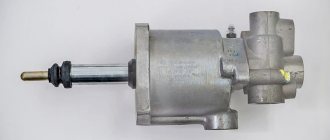
Small-sized liquid heater
Heater model “PRAMOTRONIK 16ZhD-24” – diesel, with a rated supply voltage of 24V, designed for pre-start heating and automatic maintenance of the thermal regime of a diesel engine with liquid cooling of trucks of all brands, as well as heating and automatic temperature maintenance in the cabin (salon) of a vehicle , buses, stationary premises at ambient temperatures down to minus 45 ° C.
The heater operates independently of the car engine.
It is the main component in the vehicle engine coolant heating system.
The heater is included in the liquid cooling (heating) system of the engine simultaneously with an additional electric pump (pump), which circulates coolant through the heater, engine and cabin heater.
Fuel is supplied to the heater by a special plunger pump through a system of intake and discharge pipelines.
The heater is started and turned off “manually” using the control panel.
Electric power is supplied from the vehicle battery and is connected to the control panel, electric pump and fuel pump using connecting harnesses. The electrical connection diagram is shown in Fig. below
The heater is an autonomous heating device and consists of the following main components (Fig. below):
— Heat exchanger (item 2);
— Air blower (item 3);
— Control unit (item 4);
— Glow plug (item 5);
— Flame indicator (item 6);
— Incoming liquid temperature sensor (overheating sensor) (pos. 8);
— Outgoing liquid temperature sensor (item 7).
The heat source is gases obtained from the combustion of the fuel mixture in the combustion chamber. Hot gases, moving between the fins inside the heat exchanger, heat it, and the coolant, which washes the heat exchanger from the outside, heats up and carries this heat into the cooling system.
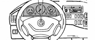
The heater is controlled by a control panel, which should be located on the vehicle dashboard. On the front panel of the remote control there is a knob position 1 (Fig. below) for a potentiometer to set the air temperature inside the car. The temperature can be set from +150C to +300C.
In addition, on the front panel of the remote control, there is a button pos. 2 and button pos. 3, each of which is designed to turn the heater on and off.
The front panel of the control panel also contains 2 LEDs that indicate the status of the heater:
— do not light up, the heater does not work;
— glows green, the heater is working;
— flashes red at intervals and emits a beep (fault code), the heater is not working properly.
After pressing the button to start the heater, the control unit diagnoses all elements of the control system and their electrical circuits. If all elements are in good condition, the control unit starts operating the heater according to the specified program, when you press the button pos. 2, the heater starts working according to program No. 1, and when you press the button pos. No. 3 according to program No. 2.
The beginning of work according to program No. 2 and No. 1 do not differ from each other until the heater reaches the average operating mode.
At the beginning, the control unit smoothly increases the voltage on the glow plug, the porous structure in the combustion chamber is heated, then fuel and air are supplied, the combustion process begins, which is controlled by the control unit using a flame indicator. When stable combustion is achieved and a sufficient signal from the flame indicator is achieved, the control unit turns off the glow plug and the combustion process is subsequently maintained by the continuous supply of fuel and air to the combustion chamber.
When working according to program No. 1, the control unit switches the heater operation to the “FULL” mode, and according to program No. 2 to the “MEDIUM” mode
If for some reason the heater does not start, the process of starting the heater is automatically repeated. After 2 unsuccessful attempts to start the heater, it automatically turns off. The red LED on the control panel lights up in the form of repeated flashes through a pause and a sound signal, which indicate that the startup attempts have been exhausted “code No. 2”.
At this time, the control unit purges the combustion chamber for 5 minutes. This purge is carried out when any malfunction of the heater occurs. After the purge is completed, the electric pump is turned off. The fault code is displayed and signals for 10 minutes.
The fault code can be cleared with the corresponding program button by pressing and holding it pressed for 5 seconds.
When you press the button pos. 2, the heater will work according to program No. 1, which provides for quick preparation (heating) of the engine for starting, i.e. the heater enters the “full” mode and in this mode heats the liquid to a temperature of +70 °C, and then switches to the medium operating mode and brings the coolant temperature to +75 °C, after which it switches to the “small” mode and continues to heat the liquid to a temperature of +80 °C. When the temperature reaches +80 °C, the heater goes into standby mode, i.e. the combustion chamber turns off and the electric pump continues to operate.
The “standby” mode continues until the coolant temperature drops to +55 °C, at this temperature the control unit starts the heater and runs program No. 1 again.
The heater can be turned off at any time during operation by pressing the button pos. 2, or transfer the heater operation to program No. 2 by pressing button pos. 3.
When program No. 2 is running, the control unit measures the temperature of the incoming liquid into the heater, and when this temperature reaches +40 °C, it turns on the cabin heater fan, heating the air in the cabin begins and maintaining the air temperature set on the control panel. The control unit, together with the control panel, automatically maintains the set temperature in the vehicle cabin. The temperature in the car cabin is measured by a remote sensor
temperature, which should be installed in a place where it is necessary to maintain a given temperature, and the sensor should be well blown with air.
The temperature is adjusted by turning the cabin heater fan on and off.
Working in the “medium” mode, the heater heats the coolant to +60 °C and switches to the “small” operating mode and then, having heated the liquid to +70 °C, it goes into standby mode, the combustion chamber is turned off, only the electric pump (pump) works. In this mode, the coolant temperature is reduced to +40 °C.
When the temperature reaches +40 °C, the control unit turns on the heater and program No. 2 is processed again.
The heater can operate according to program No. 1 in the “FULL” mode and not reach the set coolant temperature of +70 °C; the heater will operate in this mode until the heat input exceeds the heat output.
In this state, the coolant temperature will begin to increase and when it reaches +70 °C, the heater will switch to the “MEDIUM” operating mode, in which case the coolant temperature can drop to a temperature of +65 °C. At this temperature, the control unit will switch the heater to the “FULL” operating mode; if the coolant temperature rises and the heater heats the coolant to +75 °C, the heater will switch to
operating mode "SMALL". If the coolant temperature decreases, then when it drops to +70 °C, the control unit will switch the heater to the “MEDIUM” operating mode.
Possible malfunctions, their causes and methods for eliminating them
Some problems that can be fixed on your own:
— the buttons on the control panel are not illuminated;
To determine the reasons, it is necessary to check (replace) the fuse, check the power circuit and the connectors of the harnesses connecting the remote control and the heater.
— the heater does not start;
With this malfunction, code No. 2 “Two attempts to start have been exhausted” is displayed. Check the presence of fuel in the fuel tank and the operation of the fuel pump.
All possible malfunctions that may occur during the operation of the heater are displayed in the form of fault codes on the control panel. Each fault code is displayed on the control panel in the form of repeated flashes and pauses of the LED (red) and is accompanied by an audible signal.
Attention: The sound signal can be turned off at this time by pressing and holding the corresponding program button for 2÷3 seconds.
An explanation of the number of blinks when the corresponding program malfunctions (fault codes) is shown below.
Number of flashes before pause Malfunction Recommendations for troubleshooting
1 Battery voltage is not normal
Check the voltage at the connector. The voltage should be from 20÷30 V. If the voltage is less than 20 V, charge the battery or replace it; if it is more than 30 V, check the voltage regulator.
2 Two startup attempts were used
Check the presence of fuel in the fuel tank, disconnect the fuel line from the heater and check the fuel supply, if there is no fuel, check the operation of the fuel pump, replace if necessary. Check the air intake filter and exhaust pipe for blockages.
3 Flame interruption in the combustion chamber
Check the amount of fuel supplied. Check the air intake filter and exhaust pipe for blockages. If the heater starts and turns off, check the flame indicator and replace if necessary.
4 Electric pump malfunction
Check the electric motor circuit with the harness for open circuit and short circuit. The resistance between the terminals should be
5 Fuel pump malfunction
Check the fuel pump harness for opens and short circuits without disconnecting it from the pump. The resistance between the terminals should be
6 Ambient temperature sensor circuit malfunction
Check the connector connecting the remote control and the ambient temperature sensor, check the harness for a break.
7 Blower motor circuit malfunction
Check the motor circuit and replace the air blower if necessary.
8 Faulty glow plug
Check the spark plug chain.
There must be resistance
9 Lack of communication with the control panel
Check the connector connecting the control panel to the heater control unit.
10 Inlet fluid temperature sensor circuit malfunction
Check the connector connecting the sensor to the control unit, check the harness for a break.
11 Outgoing fluid temperature sensor circuit malfunction
Check the connector connecting the sensor to the control unit, check the harness for a break.
13 Heat exchanger overheating
Check the electric pump, the presence (level) of coolant,
Let's begin... | <manuals> | ENCYCLOPEDIA | Services... | Contacts | Home Site Map
Deciphering fault codes
The table of standard engine heater failures is shown above. There is information for the most common models. Let's look at common codings that are relevant for dry heaters.
Pramotronic: error 1
The system indicates incorrect voltage in the on-board circuit. It is necessary to check the state of charge of the battery and the relay voltage regulator. View power lines. Sometimes the problem comes from oxidized contacts.
Mistake 2: what to do
The heater cannot start. The fuel supply, voltage and ventilation system are checked. Experienced drivers point to problems with carbon deposits on the glow plug - the quality of domestic fuel affects it.
Error 4
The heater module is forcibly locked; 6 consecutive startup attempts have been made. Breakdowns and troubleshooting are already listed above.
Pramotronic: fault 5
The fuel pump has failed. You will need to check the wiring, fuses and condition of the device windings. When ringing the motor, the resistance should be at least 20 ohms.
Error7
The air blower circuit is broken. Check the wiring and contact groups.
Error 9
Communication with the control panel is lost. The element connection bus and its contacts are checked.
Error 13: what does it mean?
It takes time for the device to cool down - the heat exchanger is overheated.
Pramotronik 143.8106
The HG27 lamp does not light up when the heater is turned on.
Break in the power supply circuit using thermobimetallic fuse FU25.
Poor contact at the battery terminals.
Break in the heater power wiring harness.
The polarity of the heater power wires on the battery is reversed.
The fuel filter is clogged.
The tightness in the supply line of the heater fuel line is broken.
Thickening of fuel in the fuel line during climate change.
The tightness in the supply line of the heater fuel line is broken.
Solidification of fuel in the fuel line during climate change.
The heat exchanger overheated, the heater thermal fuse tripped.
Malfunctions that you can fix yourself
| Malfunction | Recommendations for elimination |
| The “Heating” and “Ventilation” buttons are not illuminated on the control panel. | To determine the reasons, it is necessary to check (replace) the fuse, check the power circuit and the connectors of the harnesses connecting the remote control and the heater. |
| The heater does not start. | With this malfunction, code No. 2 is displayed: “Two attempts to start have been exhausted.” Check the presence of fuel in the fuel tank and the operation of the fuel pump. |
Timer-thermostat Pramotronic (15.8106, 151.8106, 141.8106)
| Code | Timer indication | Indication on the warning lamp | Malfunction |
| 1 | E-01 | 1 flash | Failure to start the heater. |
| 2 | E-02 | 2 flashes | No flame ignition. |
| 3 | E-03 | 3 flashes | The supply voltage is below normal. |
| 4 | E-04 | 4 flashes | Flame indicator circuit malfunction. |
| 5 | E-05 | 5 flashes | Malfunction of the high voltage power supply circuit. |
| 6 | E-06 | 6 flashes | Temperature sensor defective. |
| 7 | E-07 | 7 flashes | Solenoid valve circuit malfunction. |
| 8 | E-08 | 8 flashes | Heater fan motor circuit malfunction. |
| 9 | E-09 | 9 flashes | Electric pump circuit malfunction. |
| 10 | E-10 | 10 flashes | The supply voltage is higher than normal. |
| 11 | E-20 | Lack of communication between the control unit and the timer-thermostat. |
Safety requirements and warnings
1. Repair of the heater must be carried out by organizations and persons authorized by the manufacturer. 2. The heater must be connected using a 2-wire circuit directly to the battery, regardless of the “mass” of the vehicle. 3. It is prohibited to connect the heater to the electrical circuit of a car that does not have a battery. 4. When installing and dismantling the heater, the safety measures provided for in the rules for working with the electrical network and fuel system of the vehicle must be observed. 5. When carrying out electric welding work on a car or repair work on the heater, it is necessary to disconnect it from the battery. 6. It is prohibited to use the heater in places where flammable vapors, gases or large amounts of dust may form and accumulate. 7. It is prohibited to use the heater when parking the vehicle (ATS) in enclosed spaces (garage, workshops, etc.) to avoid poisoning from exhaust gases. 8. When refueling the car, the heater must be turned off. 9. To avoid warping of plastic parts, boiling of the coolant inside the heater and failure of temperature sensors, it is prohibited to disconnect electrical connectors or disconnect the heater from the power supply until the end of the purge cycle. 10. After turning off the heater, it should be turned on again no earlier than after 5÷10 seconds. 11. If malfunctions occur in the operation of the heater, you must contact specialized repair organizations authorized by the manufacturer. 12. When washing a car, it is prohibited to direct a stream of water under a pressure of more than 2 bar to the elements included in the heater. 13. When the vehicle is wading, the water level should not exceed the level of the heater exhaust pipe.
Heater Errors
Eberspacher 001 01 Voltage is less than rated - the heater is working 002 02 Voltage is higher than rated - the heater is working 004 03 Fan short circuit (D2I) 005 05 Alarm wire short circuit (D2I) 009 09 Heater switched off by TRS system (D2I / D9W) 010 0A Voltage is higher rated (heater stopped) 011 0B Voltage less than rated (heater stopped) 012 0C Overheating - fuel pump is turned off 013 0D Temperature sensor recorded high temperature 014 0E Large difference in t values. Dutch overheating and sensor regul. t (D3W / D9W) 015 0F The heater has overheated many times - the heater is turned off (D2I / D9W) 017 11 Repeated overheating (t has exceeded the 2nd response threshold) (D3W) 020 14 Glow plug / core is faulty 021 15 Short circuit of the plug / core Enjoyment 022 16 Failed candle / incandescent relay (d2W) 023 17 internal defect of the relay regulator R2 candle / incandescent rod 024 18 Short short circuit of the relay-regulator of incandescent 025 19 Diagnostic connector 029 1d air fan in position 5 does not work. R3 030 1E Air fan does not work in all positions (R3-D3W) 031 1F Air fan does not work in all positions (R3-D3W) 032 20 Air fan does not work in all positions (R3-D3W) 033 21 Air fan does not work in all positions (R4-D2I / D9W) 034 22 No contact with the cooling system solenoid valve. (D2W / D9W) 035 23 No contact with the average capacity relay 036 24 Short circuit of the average capacity relay 037 25 Water pump does not rotate (D2W / D9W) 038 26 No contact with the cabin heating fan relay (D2W / D9W) 039 27 Short circuit of the relay cabin heating fan (D2W / D9W) 040 28 Electromagnetic short circuit. cooling system valve (D2W / D9W) 042 2A Short circuit of the water pump (D9W) 043 2B Short circuit of the cable from the heater ECU to the fuel pump (D9W) 047 2F Short circuit of the fuel pump 048 30 No contact with the fuel pump 050 32 The heater started many times but did not work (relay R3) 051 33 Flame appeared immediately after pressing the heater start button 052 34 No start (purge restart) 053 35 Flame stops during start-up 054 36 Flame stops at max. performance 055 37 Flame stops in the medium performance position 056 38 Flame stops in the low performance position 057 39 Short circuit of the flame sensor (photoresistor) 058 3A Heater is off, but there is a flame in the combustion chamber (D2W) 059 3B Water temperature rises too quickly (D9W) 060 3C Нет контакта с датчиком регулировки температуры 061 3D Короткое замыкание датчика регулировки температуры 062 3E Нет контакта с потенциометром (D2H / D2I) 063 3F Короткое замыкание потенциометра (D2H / D2I) 064 40 Нет контакта с датчиком пламени 065 41 Короткое замыкание датчика пламени 071 47 No contact with overheat sensor (D3W / D9W) 072 48 Short circuit of overheat sensor (D3W / D9W) 073 49 Overheat sensor detected rapid temperature rise (D9W) 090 5A Spontaneous error 091 5B High voltage surge (high voltage wires, CB radio, etc.) 092 5C Heater ECU defective - ROM fault 093 5D Heater ECU faulty - RAM fault 094 5E Heater ECU faulty - EEPROM fault 096 60 Temperature sensor Heater ECU faulty (D2I) 097 61 Heater ECU faulty (D2I / D2) W/D9W) 255 FF Memory cleared but EEPROM faulty
How does it work
The heater is an autonomous heat source and operates independently of the car engine. The device includes:
- burner;
- fuel pump;
- water pump;
- Control block;
- remote control panel;
- connecting wires.
The operating principle of the 14TS-10 heater is based on the transfer of heat from burnt fuel to a coolant pumped through a heat exchanger. The device is located under the hood and connected to the engine cooling system.
The fuel mixture is ignited after the combustion chamber is purged with air. A glow plug is used as a fire source, which remains in operation until the torch burns steadily. Diesel fuel is supplied to the combustion chamber by an electromagnetic fuel pump from its container or car tank. After heat is transferred to the walls of the heat exchanger, the exhaust gases are released under the car.
Automation ensures safe operation of the device and turns it off in the following cases:
- 2 unsuccessful startup attempts;
- flame torch failure;
- increase in network voltage more than 30 V and decrease below 20 V;
- heat exchanger overheating.
What functions does it perform?
The main function of the preheater is to preheat the engine before starting, mainly used in the cold season.
Can also be used in winter at sub-zero temperatures to prevent windshield wipers from freezing and icing up the windshield.
In some cases, it can be used to heat the driver’s cabin: heated air from a hair dryer is blown into the cabin.
Malfunctions of Pramotronic engine preheaters
Pramotronik is a modern domestic pre-heater that is not inferior in its characteristics to foreign analogues, however, this does not exclude the possibility of its breakdown.
In this article we will look at all possible malfunctions and errors of Pramotronic car engine preheaters.
Attention! When operating and repairing railways, it is necessary to strictly observe safety regulations and take measures to prevent the possibility of a fire.
Warranty
1. The warranty period of the heater corresponds to the warranty period of the car; 2. During the warranty period, malfunctions caused by the manufacturer are eliminated by the personnel of authorized service centers with the supply of the required spare parts at the expense of the manufacturer. 3. The manufacturer does not accept claims for incomplete heaters, heaters with mechanical damage or with a broken warranty seal. 4. This warranty does not cover defects resulting from:
General signs of malfunction of Pramotronic flare heaters
| Symptoms of a problem | Possible reasons |
| The heater does not start. | There is no voltage supply, the connection polarity is reversed. |
| There is no ignition. | Lack of fuel. |
The fuel pump is not working.
The solenoid does not open.
The injector is clogged, the connection of the fuel lines is leaking (the pump sucks in air).
Incorrect fuel spray angle, less than 80º.
Low motor speed.
Pramotronik 30ZhD24, 35Zh24, 141.8106
Lamps HL1 and HL2 do not light up when the heater is turned on.
Poor contact at the battery terminals.
Break in the heater power wiring harness.
The polarity of the heater power wires on the battery is reversed.
The fuel filter is clogged.
The tightness in the suction line of the heater fuel line is broken.
Thickening of fuel in the fuel line during climate change.
The fuel suction line is not tight.
Thickening of fuel in the fuel line during climate change.
The heat exchanger overheated, the thermal fuse tripped.
Recommendations
1. To ensure long-term operation of the heater, it is recommended to briefly turn on the heater for about 5 minutes once a month throughout the year (including during the warm period of the year). Switch on when the ambient temperature at the control panel and temperature sensor is below +30 °C. In this way, sticking of the moving parts of the fuel pump (which can occur from low-quality fuel) can be prevented. 2. Reliable operation of the heater depends on the fuel used depending on the ambient temperature. Recommended fuel types are shown in Table 2.
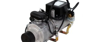
Purpose of the device
Unit features
For KAMAZ vehicles, autonomous liquid pre-heaters are used, which operate on diesel fuel. The main advantage of these variations is that they can provide effective engine warming up with minimal consumption.
Pre-heater KamAZ
It should also be noted that the device connects to the car’s electrical network, but does not consume a lot of electricity. It turns out that when using the KAMAZ preheater, the battery operates autonomously and does not require third-party power sources.
In more outdated truck models, simple devices of the 4310, 520 series are installed. These variations have a simple design and do not differ in complex installation schemes. Modern units are in great demand in new KAMAZ vehicles, buses, special equipment and tractors. But despite the difference in functions, the operating principle of the devices consists of standard steps.
VIDEO: Preheating a cold engine
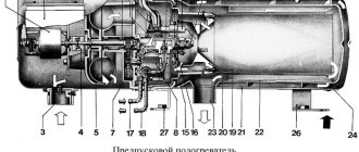
Design and device
The design of the KAMAZ pre-heater includes several main components:
The main element is the boiler compartment, which consists of 4 durable cylinders that form a heat exchanger. This part includes 2 cavities that facilitate the unhindered passage of exhaust gas and coolant circulation. There are 3 tubes on the outer part of the engine heater, 2 of them are intended for draining or supplying antifreeze, one is for exhaust gas removal.
Pre-heater device
The exhaust gases hit the damped part of the boiler, which due to this action change direction and flow to the outlet pipe. In this case, thermal energy is consumed for heating in the engine sump.
On the reverse side, at the open end of the boiler compartment, a burner is mounted, which includes:
The pump is considered a separate unit that combines three main pumps - liquid, fuel, air. It is in this system that it differs from other types of pre-heaters.
For example, a modification of the PZD 30 heater has a pumping apparatus, which is designed as a separate unit. Such a device is installed both above the boiler room and in any most convenient place. In this case, the device is connected with hoses of different diameters and lengths.
Pumping unit design
Devices 15-8106 and other similar analogues are mounted on the edge of the boiler, near the burner. This installation option makes it possible to eliminate the need to use long hoses, which leads to a significant reduction in the dimensional parameters of the entire preheater.
Boiler heater design
The remote control device has an electronic unit, with the help of which the operating modes are configured in 4 main positions. This element also allows you to configure relays, various fuses, and a spark plug switch.
It should be noted that modern modifications in the design have a variety of controllers. First of all, users note the temperature and flame sensor. These elements make it easier to turn on the device and make it possible to fully control its operation.
Circuit diagram for switching on the engine starting heater
This eliminates the possibility of breakdowns requiring repair. But according to the principle of operation, these models of KAMAZ heaters do not have any special differences.
Recommendations for use
The key to a long service life of any equipment is compliance with the rules of use. In general, the following stages should be distinguished:
Connection diagram of the heater to the engine cooling system
The preheater is considered a high hazard. If used incorrectly or made a mistake during installation, this particular device can become the primary cause of fire.
While the heater is operating, you need to stay nearby and ensure that no leaks form. If a liquid leak is detected, the device must be turned off immediately and not used until the problem is resolved.
Safe Operation Requirements
The essence of the functioning of the KamAZ railway
The liquid heater of KamAZ SHAAZ PZhD is aggregated to the system of liquid-type heating and cooling equipment of KamAZ.
The device must contain a coolant. Reference! The unit itself is independent of motor activity.
The equipment is powered by the vehicle.
When the heater is activated, fuel is sent. It starts from the electromagnetic type pump and passes through the spark plug bushing. The flammable substance comes into contact with air, which enters through the pipe. The final mixture is ignited by a hot candle. Then it turns off.
The combustion procedure is maintained due to the constant supply of combustible substance with air. Hot steam heats the walls of the heat exchanger equipment. The exhaust gases are sent through a pipe and then enter the atmosphere.
Many motorists have not encountered how to start the pre-heater of KamAZ 5320 30 kW PZD. In reality, this procedure is not difficult.
To start the KamAZ railway, a number of actions must be performed.
- Activate the battery deactivator.
- Open the valve on the fuel tank and fill the KamAZ Euro 4 fuel system with the substance.
- Check operation using special pumping equipment.
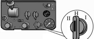
- Place the PZD lever in position III.
- Activate the power button for the electrical heating system.
- 60 seconds is set if the temperature outside the window is down to -40 °C. At temperatures below -50 °C, set to 90 seconds.
- Place the PZD lever in position I.
- A characteristic hum should appear in the heat exchanger device if you hold the control handle. This sound indicates the substance is igniting.
- Lower the handle.
Reference! A smooth hum indicates that all mechanisms and parts are functioning as expected. This means there is no need to worry about the condition of the mechanism. If the sound is uneven, then there is something wrong with the operation of the internal combustion engine preheater. Diagnostics is required.
If activation is unsuccessful, move the lever to the zero position. You can repeat the procedure after waiting one minute. If after two attempts the situation has not changed, then you need to understand why the device does not start.
Pramotronik 143.8106
The HG27 lamp does not light up when the heater is turned on.
Break in the power supply circuit using thermobimetallic fuse FU25.
Poor contact at the battery terminals.
Break in the heater power wiring harness.
The polarity of the heater power wires on the battery is reversed.
The fuel filter is clogged.
The tightness in the supply line of the heater fuel line is broken.
Thickening of fuel in the fuel line during climate change.
The tightness in the supply line of the heater fuel line is broken.
Solidification of fuel in the fuel line during climate change.
The heat exchanger overheated, the heater thermal fuse tripped.
Basic mistakes and ways to solve them
A distinctive feature of the PZD 14TS-10 system is that the operator can independently determine the cause of the breakdown. For this, the developer has provided a special LED identification system. All you need to do is count the number of times the LED blinks. Then, depending on their number from 1 to 10, the operator can find out the reason and method of repairing the device. Error codes and instructions for solving them are presented in the image below. We recommend that you copy this table and keep it in your car to quickly resolve the problem.
Control unit and control panel
The block performs three options: performs primary diagnostics and checks errors during operation; starts the heater and operates it in economy or pre-start mode; turns off the device due to inoperability of the components or some parameter that has exceeded its limit, as well as due to flame failure.
Using the remote control, you can control the autonomy - turn it on and off manually, set the heating time and control the ventilation system in the cabin. Instruction 14TS-10 is not complicated, but you need to study it. All actions are performed using the panel.
The remote control will help you with control