Gearbox type Gear ratio [I] Gearbox torque Service factor (service factor) Drive power Efficiency factor (Efficiency) Explosion-proof versions Reliability indicators Drive calculation service
This article contains detailed information on the selection and calculation of a gearmotor. We hope the information provided will be useful to you.
When choosing a specific gearmotor model, the following technical characteristics are taken into account:
- gearbox type;
- power;
- output speed;
- gear ratio;
- design of input and output shafts;
- type of installation;
- additional functions.
Gearbox type
The presence of a kinematic drive diagram will simplify the choice of gearbox type. Structurally, gearboxes are divided into the following types:
Single-stage worm gear with crossed input/output shaft arrangement (angle 90 degrees).
Two-stage worm gear with perpendicular or parallel arrangement of the axes of the input/output shaft. Accordingly, the axes can be located in different horizontal and vertical planes.
Cylindrical horizontal with parallel input/output shafts. The axes are in the same horizontal plane.
Cylindrical coaxial at any angle. The shaft axes are located in the same plane.
In a bevel-helical gearbox, the axes of the input/output shafts intersect at an angle of 90 degrees.
IMPORTANT! The spatial location of the output shaft is critical for a number of industrial applications.
- The design of worm gearboxes allows them to be used in any position of the output shaft.
- The use of cylindrical and conical models is often possible in the horizontal plane. With the same weight and dimensional characteristics as worm gearboxes, the operation of cylindrical units is more economically feasible due to an increase in the transmitted load by 1.5-2 times and high efficiency.
Table 1. Classification of gearboxes by number of stages and type of transmission
| Gearbox type | Number of steps | Transmission type | Axes location |
| Cylindrical | 1 | One or more cylindrical | Parallel |
| 2 | Parallel/coaxial | ||
| 3 | |||
| 4 | Parallel | ||
| Conical | 1 | Conical | Intersecting |
| Conical-cylindrical | 2 | Conical Cylindrical (one or more) | Intersecting/crossing |
| 3 | |||
| 4 | |||
| Worm | 1 | Worm (one or two) | Crossbreeding |
| 1 | Parallel | ||
| Cylindrical-worm or worm-cylindrical | 2 | Cylindrical (one or two) Worm (one) | Crossbreeding |
| 3 | |||
| Planetary | 1 | Two central gears and satellites (for each stage) | Coaxial |
| 2 | |||
| 3 | |||
| Cylindrical-planetary | 2 | Cylindrical (one or more) Planetary (one or more) | Parallel/coaxial |
| 3 | |||
| 4 | |||
| Cone-planetary | 2 | Conical (single) Planetary (one or more) | Intersecting |
| 3 | |||
| 4 | |||
| Worm-planetary | 2 | Worm (one) Planetary (one or more) | Crossbreeding |
| 3 | |||
| 4 | |||
| Wave | 1 | Wave (one) | Coaxial |
Do-it-yourself reduction gear: description, diagrams, drawing and reviews
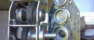
A reduction gearbox is a device that is designed to convert torque. There are worm, planetary and combined modifications. The engine with gearbox is capable of operating at high speeds. The standard model consists of a shaft, pushers and gear. If necessary, you can make a step-down device yourself.
Worm modification diagram
The worm gear design includes a wide disk with a gear next to it. The first pusher is located at the base of the gearbox. In this case, the coupling is attached to the front of the housing. To make the device yourself, first of all, a stand for the shaft is cut out. Next you need to secure the disks. Lastly, the retainer is soldered.
Assembling the planetary device
This reduction gearbox for an electric motor is distinguished by the fact that it uses a two-chamber gearbox. Pushers for modifications are installed in different sizes. To make a device with your own hands, a wide block is prepared. Next, it is important to install the pushers. The coupling is directly fixed to the clamping spring.
Experts recommend grinding the stand in advance and welding supports on it. The gear is fixed at the rear of the gearbox. The pressure plate is installed only with a stop. The clamps can be mounted with a roller mechanism. It should also be noted that there are many homemade modifications with additional stops that stabilize the shaft.
Helical gearboxes
Recently, a cylindrical homemade reduction gearbox has been actively used. You can make the device with your own hands with a short and long shaft. In this case, the stops are installed in the rear part of the housing. Some devices are assembled with one gear. Before installing the part, a block for the disks is prepared. The gearbox shaft is fixed on the stand.
The holder is allowed to be made with an emphasis. Ball bearings are fixed at the base of the shaft. Pressure plates for models can be of different sizes. If we consider compact devices, then the spring should be installed with a small diameter. It should also be noted that the gears are placed behind the shaft. The pushers should not come into contact with the disk. A cap is screwed onto the front of the housing.
Conical model drawings
This reduction gearbox can be made with longitudinal pushers. Drives are most often mounted on a short stand. A lever is installed to switch the clutch.
Many modifications are assembled with an adapter holder. The shaft is fixed behind the rack. A clutch is used to adjust the tension. At the end of the work, all that remains is to secure the lid.
The engine with reduction gearbox is capable of operating at a frequency of 50 Hz.
Reviews of combined devices
Combined gearboxes that reduce speed are highly valued among professionals. If you believe the reviews, the models are well suited for asynchronous motors. It is more expedient to use pushers made of steel plates.
Stops are used to install the discs. The coupling for modifications is fixed behind the shaft. If you believe the reviews of experts, the retainer can be cut from a regular plate.
It should also be noted that it is more advisable to install the cover with a screw clamp.
Modifications with one lock
Making a reduction gearbox with your own hands is very simple. In this case, the pushers must be installed under the stops. The box for modification can be selected as a single-chamber type. Gears can be used with a clamp.
Pressure disks are installed with a roller mechanism. The pressure disk is fixed in front of the pusher. To install the spring, use a hammer. The clutch is mounted under the disc.
Ball bearings can be used in different sizes.
Devices with two clamps
Modifications to two clamps fold with a dual camera. A total of two disks are required for assembly. The coupling itself is matched with a support spring.
Many experts say that it is more advisable to use U-shaped pushers. A lever is used to change gears. If you believe the reviews of experts, then the gears take a very long time to fill.
In this case, it is important to fix the shaft at the base of the chamber. At the end of the work, all that remains is to make a holder for the rollers.
Models with front pushrods
Reduction gearboxes for walk-behind tractors with front-mounted pushers are capable of maintaining high speeds of an asynchronous engine. The holders of the modifications are installed with roller mechanisms. Many models fold with longitudinal stops.
Before starting assembly, a chamber for ball bearings is prepared. They are fixed on the bottom of the block. The driven disk is machined to a small diameter. It should also be noted that it is important to securely fix the stops. A cover must be attached to the rear of the gearbox.
Rear pusher gearboxes
The reduction gearbox with rear pushers is in great demand. First of all, it should be noted that the models are compact. At the same time, the devices cope well with heavy overloads. The disadvantage of the models is the rapid wear of the discs. This happens due to friction of the stops. If necessary, modification can be done by yourself.
For this purpose, experts recommend preparing a narrow block and installing disks with a roller mechanism. It is more expedient to place the gear after the pushers. It should also be noted that there are modifications with brake stops. In this case, the pushers are fixed on the rack. To change gears you will have to install a lever.
After this, the drive disk is fixed. The cover for the gearbox can be selected with a screw connection. Pressure plates are usually fixed near the front pillar. The model holder fits with or without a stop. If you believe the reviews of experts, then gearboxes with two pushers are considered the most popular.
Reviews of one-stage modifications
Most experts speak positively about single-stage gearboxes. However, it is important to understand that high-quality models are assembled with adapter pushers. They use sharpened heads and do not rub against the discs. It is more expedient to install the gearbox shaft behind the partition. The gear is most often fixed in front of the rack.
It should also be noted that there are compact modifications with a small shaft. They have small pressure disks; the device is not able to maintain high engine speeds. The holders are installed in a cylindrical shape.
Pressure plates are used with and without adapters. Rollers are used to reduce friction, and bearings are installed at the base of the shaft. It is important to pay special attention to the block during assembly. In order for the case to withstand heavy loads, it must be carefully soldered.
At the end of the work, all that remains is to weld the lid.
Assembly of two-stage devices
The two-stage reduction gearbox is capable of working with high power asynchronous motors. Modern models are available with longitudinal pushers. If necessary, a two-stage modification can be made independently. For this purpose, a block is taken and working disks are placed.
It is important to carefully grind the shaft and solder a wide head. A small rod is used to secure the gear. The retainer is most often installed in the front part of the gearbox. The stop can be machined from an ordinary steel plate of small thickness. The modification shaft must not come into contact with the working discs.
It should also be noted that the devices fold with and without a coupling. If we consider the first option, then a clutch lever is installed in the block. In this case, the spring is selected with a small diameter. It is better to fix the pressure stop on the device box.
Gear ratio [I]
The gear ratio is calculated using the formula:
I = N1/N2
where N1 is the shaft rotation speed (rpm) at the input; N2 – shaft rotation speed (rpm) at the output.
The value obtained in the calculations is rounded to the value specified in the technical characteristics of a particular type of gearbox.
Table 2. Range of gear ratios for different types of gearboxes
| Gearbox type | Gear ratios |
| Worm single stage | 8-80 |
| Worm two-stage | 25-10000 |
| Cylindrical single stage | 2-6,3 |
| Cylindrical two-stage | 8-50 |
| Cylindrical three stage | 31,5-200 |
| Conical-cylindrical single stage | 6,3-28 |
| Conical-cylindrical two-stage | 28-180 |
IMPORTANT! The rotation speed of the electric motor shaft and, accordingly, the input shaft of the gearbox cannot exceed 1500 rpm. The rule applies to all types of gearboxes, except cylindrical coaxial gearboxes with rotation speeds up to 3000 rpm. Manufacturers indicate this technical parameter in the summary characteristics of electric motors.
Preliminary preparation
In order for an electric motor with a self-made gearbox to work no worse than a factory model, you need to have basic mechanical skills and be able to work with tools. No specialized skills or deep knowledge are required here. Naturally, before starting work on creating the mechanism, you must first study the structure and principle of operation of the gearbox, and also determine the following points:
- the type of gearbox being created and its design features;
- converting gear ratio;
- output gear ratio;
- expected dynamic load on the working parts of the device during operation;
- overall dimensions and weight of the future product;
- type and angle of installation;
- operating range, maximum and minimum temperatures outside and inside the device during its operation;
- launch features - full cycle or variable;
- the operating intensity of the electric motor with a 220V gearbox.
In the process of manufacturing the gearbox, the following components will be needed:
- Frame. A factory-made electric drive with a reduction gear typically has a cast iron or aluminum frame with holes made using high-precision industrial equipment. For a homemade device, a suitable housing can be selected from other equipment, for example, an old gearbox, or welded yourself from steel sheets. It is very important to achieve the correct mutual placement of shafts and gears. To facilitate further maintenance and operation of the unit, it is advisable to make the top cover removable. There should also be a hole in the lower part of the housing for grinding off used oil;
- Axles and shafts. They should become a reliable support for sprockets and gears, therefore, as a manufacturing material, it is advisable to choose high-quality steel 10-45 millimeters, which can be easily machined. For a single-stage mechanism, only shafts with rigidly fixed gears that turn along with the shafts are sufficient. The axles are placed for mounting intermediate sprockets. Installation is carried out on a key or tensioned splines;
- Set of bearings. They are used to lighten the load on the shafts during rotation. The operating efficiency, reliability and service life of the entire structure directly depend on correctly selected bearings. If an electric motor with a gearbox uses gears with straight teeth, then it is enough to install simple single-row or double-row ball-type bearings. For worm gears or helical gears, it is better to choose radial thrust or roller bearings. A good choice for a homemade mechanism would be sealed bearings with grease lubrication, which do not require special maintenance. It is better not to use used parts remaining after disassembly, but to buy new ones;
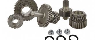
- Gears. It depends on them at what frequency the shafts will rotate and how much the gear ratio will decrease. Gears are made on special industrial metal-cutting machines, which are practically not used at home and in private workshops. The dimensions of the gears affect the size and parameters of most of the components included in the gearbox design, as well as the center distance. When installing them, special attention should be paid to the correct setting of the gap between the teeth. Lubrication oil is poured to cover the bottom of the gears. The remaining parts of the device will be lubricated during operation by splashing. It is also advisable to purchase new products, but used ones are also suitable if they are in good condition without much wear on the teeth;
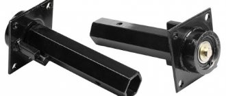
- Seals and seals. They are placed at the output of the shafts near the bearings and are used to prevent oil leakage from the gearbox housing. New products are purchased;
- Protective coupling. It reduces the likelihood of destruction of the gearbox structure when exposed to extreme loads and is available in the form of a shear pin, bellows or friction disc. It is not recommended to save money here. The clutch needs a new one;
- Bearing caps are blind or through type. They will greatly facilitate the process of installation, maintenance and replacement of bearings. You can use parts from disassembly or grind them yourself.
You also need to stock up on the necessary tools and materials, such as:
- screwdrivers of different shapes and sizes;
- assorted wrenches;
- a set of drills of different diameters;
- needle files and files;
- inverter welding machine;
- hammers, pliers and vices;
- ruler, calipers and other measuring instruments;
- steel sheets, pipe scraps, etc.
When all of the above components and tools have been assembled, you can proceed directly to the manufacture of the gearbox.
Gearbox torque
Torque on the output shaft [M2] – torque on the output shaft. The rated power [Pn], the safety factor [S], the estimated service life (10 thousand hours), and the efficiency of the gearbox are taken into account.
Rated torque [Mn2] – the maximum torque that ensures safe transmission. Its value is calculated taking into account the safety factor - 1 and the service life - 10 thousand hours.
Maximum torque {M2max] – the maximum torque that the gearbox can withstand under constant or changing loads, operation with frequent starts/stops. This value can be interpreted as the instantaneous peak load in the operating mode of the equipment.
Required torque [Mr2] – torque that meets customer criteria. Its value is less than or equal to the rated torque.
Design torque [Mc2] – the value required for selecting a gearbox. The estimated value is calculated using the following formula:
Mc2 = Mr2 x Sf ≤ Mn2
where Mr2 is the required torque; Sf – service factor (operational coefficient); Mn2 – rated torque.
Do-it-yourself homemade reduction gearbox
As a rule, a good home workshop has many devices and devices that can make manual labor easier and increase work efficiency. For example, such mechanisms include a reduction gear.
In most cases, it is needed in order to reduce the rotation speed of the output shaft or increase the torque on it. By design, the gearbox can be gear, worm or combined, as well as single or multi-stage.
Below we will look at how you can make a simple gearbox with your own hands.
What is a gearbox?
This mechanism is a transmission link that is located between the rotational devices of an electric motor or internal combustion engine to the final operating unit. The main characterizing indicators of the gearbox are:
- transmitted power;
- efficiency;
- number of driving and driven rotary shafts.
Gear or worm gears are fixedly attached to the rotational devices of this mechanism , which transmit and regulate movement from one to another. The housing has holes with bearings on which the shafts are located.
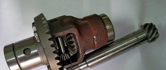
Reverse gearbox for walk-behind tractor
In a reverse gearbox, reversal is performed according to the following scheme: there is a clutch between the opposite bevel gears, which sit freely on the drive shaft.
Being in extreme positions, it clings to the splines on these gears. Therefore, when the clutch engages, the direction of rotation of the gear changes. The gears must be of the helical type. The clutch drive mechanism is a traditional fork or cam.
How to make a gearbox with your own hands?
The most important part of a reduction gearbox is its housing. It must be designed and manufactured correctly with your own hands, since the relative position of the shafts and axes, the alignment of the seats for support bearings and the clearances between gears depend on this.
Industrial gearbox housings are made mainly by casting from aluminum alloys or cast iron , however, this is completely impossible to do at home. Therefore, you can select or modify a ready-made housing to suit your needs, or weld it from a steel sheet.
Only in this case should you remember that during the welding process the metal can “lead”, and therefore, to maintain the alignment of the shafts, it is necessary to leave an allowance.
Advantages and disadvantages of the unit
Of course, the performance indicators of a branded mini tractor are much higher than those of home-made analogues. But no one tried to prove that home-made units are comparable in their technical data to purchased options.
Initially, it was understood that hand-made mini tractors would be used in fairly small areas where their working power would be sufficient. That is why the use of homemade units at the household level is becoming more and more appropriate.
Other advantages of such mini tractors include:
- Quite good indicators of the quality of plowing land. At the same time, they are in many ways comparable to the penetration depth shown by mini tractors purchased in stores.
- The operation of such devices is quite simple and does not require special knowledge and skills.
- Making a homemade unit will be a much cheaper option than buying a new mini tractor.
- A more simplified repair, because you yourself make a mini tractor from available parts, which can then be easily obtained.
- The ability to make changes to the device configuration by adding something new. This is unacceptable in purchased mini tractors, because the unit can be completely damaged.
However, you should not think that making a mini tractor at home is an unconditionally profitable enterprise. This method also has its disadvantages:
- The assembly process is quite painstaking, because it requires certain technical knowledge, as well as the ability to work with a welding machine, etc. In other words, making a mini tractor with your own hands is not suitable for everyone.
- Finding the right spare parts and components is also an additional difficulty in this matter.
As we see, there are still more advantages, which indicates that the decision was made correctly - to make homemade mini tractors with your own hands. Probably the main advantage is good cost savings, because the issue of price has become decisive lately.
Operational coefficient (service factor)
Service factor (Sf) is calculated experimentally. The type of load, daily operating duration, and the number of starts/stops per hour of operation of the gearmotor are taken into account. The operating coefficient can be determined using the data in Table 3.
Table 3. Parameters for calculating the service factor
| Load type | Number of starts/stops, hour | Average duration of operation, days | |||
| <2 | 2-8 | 9-16h | 17-24 | ||
| Soft start, static operation, medium mass acceleration | <10 | 0,75 | 1 | 1,25 | 1,5 |
| 10-50 | 1 | 1,25 | 1,5 | 1,75 | |
| 80-100 | 1,25 | 1,5 | 1,75 | 2 | |
| 100-200 | 1,5 | 1,75 | 2 | 2,2 | |
| Moderate starting load, variable mode, medium mass acceleration | <10 | 1 | 1,25 | 1,5 | 1,75 |
| 10-50 | 1,25 | 1,5 | 1,75 | 2 | |
| 80-100 | 1,5 | 1,75 | 2 | 2,2 | |
| 100-200 | 1,75 | 2 | 2,2 | 2,5 | |
| Operation under heavy loads, alternating mode, large mass acceleration | <10 | 1,25 | 1,5 | 1,75 | 2 |
| 10-50 | 1,5 | 1,75 | 2 | 2,2 | |
| 80-100 | 1,75 | 2 | 2,2 | 2,5 | |
| 100-200 | 2 | 2,2 | 2,5 | 3 | |
Drive power
Correctly calculated drive power helps to overcome mechanical friction resistance that occurs during linear and rotational movements.
The elementary formula for calculating power [P] is the calculation of the ratio of force to speed.
During rotational movements, power is calculated as the ratio of torque to revolutions per minute:
P = (MxN)/9550
where M is torque; N – number of revolutions/min.
Output power [P2] is calculated by the formula:
P2 = P x Sf
where P – power; Sf – service factor (operational factor).
IMPORTANT!
The input power value must always be higher than the output power value, which is justified by the meshing losses:
P1 > P2
Calculations cannot be made using approximate input power, as efficiencies may vary significantly.
Efficiency factor (efficiency)
Let's consider the calculation of efficiency using the example of a worm gearbox. It will be equal to the ratio of mechanical output power and input power:
ñ [%] = (P2/P1) x 100
where P2 is output power; P1 – input power.
IMPORTANT!
In worm gearboxes P2 < P1 always, since as a result of friction between the worm wheel and the worm, in the seals and bearings, part of the transmitted power is consumed.
The higher the gear ratio, the lower the efficiency.
The efficiency is affected by the duration of operation and the quality of lubricants used for preventive maintenance of the gearmotor.
Table 4. Efficiency of a single-stage worm gearbox
| Gear ratio | Efficiency at aw, mm | ||||||||
| 40 | 50 | 63 | 80 | 100 | 125 | 160 | 200 | 250 | |
| 8,0 | 0,88 | 0,89 | 0,90 | 0,91 | 0,92 | 0,93 | 0,94 | 0,95 | 0,96 |
| 10,0 | 0,87 | 0,88 | 0,89 | 0,90 | 0,91 | 0,92 | 0,93 | 0,94 | 0,95 |
| 12,5 | 0,86 | 0,87 | 0,88 | 0,89 | 0,90 | 0,91 | 0,92 | 0,93 | 0,94 |
| 16,0 | 0,82 | 0,84 | 0,86 | 0,88 | 0,89 | 0,90 | 0,91 | 0,92 | 0,93 |
| 20,0 | 0,78 | 0,81 | 0,84 | 0,86 | 0,87 | 0,88 | 0,89 | 0,90 | 0,91 |
| 25,0 | 0,74 | 0,77 | 0,80 | 0,83 | 0,84 | 0,85 | 0,86 | 0,87 | 0,89 |
| 31,5 | 0,70 | 0,73 | 0,76 | 0,78 | 0,81 | 0,82 | 0,83 | 0,84 | 0,86 |
| 40,0 | 0,65 | 0,69 | 0,73 | 0,75 | 0,77 | 0,78 | 0,80 | 0,81 | 0,83 |
| 50,0 | 0,60 | 0,65 | 0,69 | 0,72 | 0,74 | 0,75 | 0,76 | 0,78 | 0,80 |
Table 5. Wave gear efficiency
| Gear ratio | 63 | 80 | 100 | 125 | 160 | 200 | 250 | 315 |
| Efficiency | 0,83 | 0,82 | 0,80 | 0,78 | 0,75 | 0,72 | 0,70 | 0,65 |
Table 6. Efficiency of gear reducers
| Gearbox type | Efficiency |
| Cylindrical and conical single stage | 0,98 |
| Cylindrical and conical-cylindrical two-stage | 0,97 |
| Cylindrical and conical-cylindrical three-stage | 0,96 |
| Cylindrical and conical-cylindrical four-stage | 0,95 |
| Planetary single stage | 0,97 |
| Planetary two-stage | 0,95 |
Explosion-proof versions of gearmotors
Geared motors of this group are classified according to the type of explosion-proof design:
- “E” – units with an increased degree of protection. Can be used in any operating mode, including emergency situations. Enhanced protection prevents the possibility of ignition of industrial mixtures and gases.
- “D” – explosion-proof enclosure. The housing of the units is protected from deformation in the event of an explosion of the gear motor itself. This is achieved due to its design features and increased tightness. Equipment with explosion protection class “D” can be used at extremely high temperatures and with any group of explosive mixtures.
- “I” – intrinsically safe circuit. This type of explosion protection ensures the maintenance of explosion-proof current in the electrical network, taking into account the specific conditions of industrial application.
Manufacturing of the product body
Experts consider the body to be the most important part of the device. The frame must be properly designed and assembled, because the position of the axes and working shafts, the alignment of the holes for the bearings, and the distance between the gears and belt mechanisms depend on it.
In the factory, housings for reduction gearboxes are made by casting from cast iron or aluminum alloys. It is simply impossible to make such a blank on your own. For this reason, it is necessary to find or remodel the factory housing. It can also be welded from iron sheet.
Some home craftsmen were able to find a simple way out of the situation. In order not to engage in boring work, it is necessary to completely weld the frame. The support bearings will be installed in small sections of metal pipes. They need to be placed in the working position, and then secured well with fastening materials or welding.
Experts advise making a special removable cover on the body for easy maintenance of structural components. It is worth making a drain hole at the bottom, which is necessary to drain the old oil.