How to make a reduction gearbox with your own hands
Owners of home workshops have many devices and devices that greatly facilitate manual labor and increase work efficiency. One such mechanism is a reduction gearbox. It is mainly used to change the rotation speed of the output shaft downward or increase the torque on it. By its design, this device can be combined, worm or gear, as well as single- and multi-stage. Many people make a reduction gearbox with their own hands.
Self-assembly
Some models of gearboxes are sold at a high price - 11-18 thousand rubles, so garden owners often ask the question of how to make a gear reducer in a home workshop.
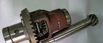
To make a homemade walk-behind tractor transmission unit, you need a welding machine, a hacksaw, a hammer, pliers, an electric drill, screwdrivers and other tools. The components used are shafts and gears of gearboxes from cars or old Soviet chainsaws of the Druzhba type.
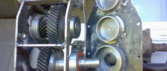
The most complex part of the gear mechanism is the housing. As a rule, borrowed components are incompatible with sold gearbox housings intended for walk-behind tractors. In this case, there are two options - use ready-made housings from gearboxes or make them yourself from two thick plates with holes for shafts with bearings.
The housing is marked along the axes relative to the assembled two- or three-stage gear transmission and is prepared for pressing bearings into holes reinforced with wide journals. The housing is then sealed and filled with oil. The output shaft of the resulting gearbox is connected to the walk-behind tractor pulley, and the input shaft is connected to the engine.
What is a gearbox?
This mechanism is a transmission link that is located between the rotational devices of an electric motor or internal combustion engine to the final operating unit.
The main characterizing indicators of the gearbox are:
- transmitted power;
- efficiency;
- number of driving and driven rotary shafts.
Gear or worm gears are fixedly attached to the rotational devices of this mechanism , which transmit and regulate movement from one to another. The housing has holes with bearings on which the shafts are located.
Common faults
Gearbox failure can be avoided with proper operation and regular maintenance. You should carefully study your passport. It specifies the types of maintenance and their frequency. It is necessary to change the oil regularly and constantly top it up. Compliance with the operating mode will keep the unit intact.
The main gearbox malfunction is associated with its overheating. This happens in the absence of lubrication and the use of oils of other brands. Otherwise, the unit will overheat and the gear may jam.
Bearings have their own safety margin. Their service life is indicated in the passport. If you do not replace them with new ones in time, the nodes begin to crumble. The balls will fall out and the shaft will begin to rotate with great effort and jerking.
Between the body and the covers: top and side, along the plane of the connector, a sealant is laid during assembly. It prevents oil from leaking out. If it is not changed in time, liquid will leak from all connectors.
Overloads and sudden switching on lead to tooth destruction. When the transmission mechanism does not match the engine, it will not last long.
How to make a gearbox with your own hands?
The most important part of a reduction gearbox is its housing. It must be designed and manufactured correctly with your own hands, since the relative position of the shafts and axes, the alignment of the seats for support bearings and the clearances between gears depend on this.
Industrial gearbox housings are made mainly by casting from aluminum alloys or cast iron , however, this is completely impossible to do at home. Therefore, you can select or modify a ready-made housing to suit your needs, or weld it from a steel sheet. Only in this case should you remember that during the welding process the metal can “lead”, and therefore, to maintain the alignment of the shafts, it is necessary to leave an allowance.
Many masters do it differently. In order not to bother with boring work, they begin to weld the body completely, and instead of sockets for support bearings they use pipe sections , which are set in the required position and only after that are finally secured in place by welding or bolts. To facilitate maintenance of the gearbox, it is necessary to make a removable top cover at the housing, and a drain hole at the bottom, which will be used to drain used oil.
The gears are supported by the axles and shafts of the gearbox. Typically, in a single-stage mechanism, only shafts with rigidly mounted gears are used. In this case, both gears rotate together with their shafts. The axle is used when it is necessary to insert an intermediate gear into the gearbox. It begins to rotate freely on its axis with minimal clearance , and to prevent it from moving sideways, it is fixed with a nut, a thrust collar or locking split washers. Shafts should be made of steel, which has good strength and excellent machinability.
The bearings in the gearbox serve as supports for the shafts. They perceive the loads that arise during the operation of the mechanism. The reliability and performance of the gearbox depends entirely on how correctly the bearings were selected.
For a do-it-yourself mechanism, it is best to choose closed type bearings , which require minimal maintenance. They are lubricated with grease. The type of bearings directly depends on the type of load. When using spur gears, ordinary single or double row ball bearings will suffice. If the mechanism contains helical gears or worm gears, then an axial load begins to be transmitted to the shaft and bearings, which requires the presence of a ball or roller angular contact bearing.
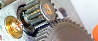
Another quite important part of the gearbox is the gears. Thanks to them, you can change the rotation speed of the output shaft. To make gears, you need special metal-cutting equipment, so to save money you can use ready-made parts from decommissioned devices.
It is very important during the installation of gears to set the correct gap between them, because the noise level that occurs during operation of the gearbox and the load capacity depend on this. It is best to lubricate the gears with liquid industrial oil, which is poured in such a way that it covers the teeth of the lower gear. The remaining parts are lubricated by spraying oil throughout the internal cavity of the mechanism.
Shaft seals prevent oil from leaking out of the gearbox. They are installed at the shaft outputs and secured in bearing caps. To prevent emergency destruction of mechanism parts from heavy loads, a safety clutch is used. It comes in the form of a bellows, spring-loaded friction discs or a shear pin. The installation process is greatly facilitated by bearing caps , which can be through or blind. They are selected from ready-made parts or turned on a lathe.
Types of gear units
The transmission of rotational motion from the motor shaft to the actuator shaft can be carried out by direct connection of the axes, if the speed and power of rotation of the engine are acceptable for operation, and the axes of the drive and driven shafts coincide. Such cases are extremely rare, and with several attachments for different purposes, direct transmission absolutely cannot be used. To match the speed and power of the drive and driven shafts, 4 types of mechanisms and their combinations are used. Main types of gears:
The worm gear is structurally limited by the speed-reducing function; the rest can be used in both downshifts and overdrives. In addition, such a gearbox always has a driven axis perpendicular to the drive shaft. This scheme is called an angular gearbox. In addition to the worm gear, you can change the direction of the axis using a spatial planetary mechanism. Belt and chain drives keep the driven axis parallel to the engine axis. In simple devices, reverse is possible only when the rotation of the engine changes.
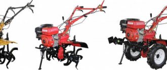
Motoblocks use engines with a high number of revolutions per minute, which can be verified in the product data sheet. This means that you need to make a gearbox with your own hands to reduce the speed, and it is better to choose what type of homemade gearbox for a walk-behind tractor, knowing the characteristics of each type.
Belting
The pulley or belt that transmits rotation from shaft to shaft is familiar to every motorist who has looked under the hood of the engine compartment. The rotation speed reduction coefficient is determined by dividing the radius of the small driven wheel by the radius of the large driving wheel.
The advantages of belt gearboxes are their ease of manufacture and repair, and a wide variety of parts. And the disadvantages of the belt:
- belt stretching, decreased adhesion to the pulley due to temperature and wear;
- slippage during sudden increases in torque;
- short service life.
The shortcomings are compensated by using a spring-loaded roller that presses on the surface of the belt between the wheels, and by using a toothed belt on pulleys with transverse chamfers. Belt gearboxes require the drive and driven pulleys to be in the same plane; bending or twisting the belt will quickly lead to it breaking.
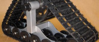
Chain type
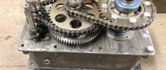
The operating principle of a chain drive is similar to a belt drive, but sprockets are installed instead of pulleys, and the belt is replaced by a chain. Such a homemade gearbox will not allow slipping, and under similar conditions it will work much longer.
Just like a belt gearbox, a chain gearbox must have drive and driven sprockets in the same plane, and its gear ratio is calculated by the ratio of their teeth. The weight of this design is greater than that of a belt design, but it is safer to install it on powerful walk-behind tractors.
Unlike a belt drive, a chain drive requires caution or additional protective measures. If a rotating implement collides with a thick root in the soil, its drag force will be transferred to the motor, possibly damaging it. Until the engine fails or switches off, it will try to rotate with maximum power along with the frame around the driven axis of the gearbox. The greater the engine power, the stronger the tipping torque will be.
The gear ratio of a chain gearbox can be higher than that of a belt gearbox of the same size, since the drive sprocket, even having a small size, will not allow the chain to slip.
In terms of cost, ease of assembly, and prevalence of parts, a chain drive is not inferior to a belt drive.
Using gears
A walk-behind tractor with a gear reducer is more reliable and durable than one with a chain or belt drive. Gear structures are installed on factory products, and not only on walk-behind tractors. The units are small in size as a result of combining two gears with different diameters on one axis. For a walk-behind tractor, for example, a gearbox from an Ant scooter is perfect. But you can make your own using gears from motor vehicle gearboxes.
The required gear ratio can be provided by a planetary mechanism, in which satellite gears are installed between the outer and sun gears, mounted on a fixed ring - the carrier:
For a reduction gearbox, the sun gear is mounted on the drive shaft. The planetary gear carrier is mounted on a stationary housing, and the outer gear is connected to the actuator, rotating in the direction opposite to the sun gear.
The gear ratio of such a gearbox can be calculated as the ratio of the number of teeth on the sun gear to the number of teeth on the external gear.
To change the direction of the axis of rotation in gearboxes, a spatial planetary mechanism is used, in which the gears, in order to change the direction by 90 degrees, must be beveled to a cone of 45 degrees each. The diameter of the gears can be different, which can be used to change the gear ratio.
For a walk-behind tractor, such an angular gearbox is rarely made by hand, since planetary gears of the required size still need to be looked for. Changing the axis of rotation is often done using ready-made factory gearboxes or a worm pair.
Read also: Programs for drawing electrical circuits according to GOST
Worm-gear
To change the direction of the rotation axis perpendicularly and create a large gear ratio, contact of a flat gear with an Archimedean screw is used.
Transmission of rotation from the actuator to the motor is not possible. This is a unique feature of the worm gear; other types of gears do not have this property. The output rotation speed can be reduced by as many times as the number of teeth the gear has. This transmission is distinguished by its ease of assembly, high friction, small size, and great popularity.
In order to make a worm gearbox with your own hands, you need to select a gear with a number of teeth equal to the reduction in rotation speed in times, as well as with a pitch between the teeth equal to the pitch of the worm flange.
Reversing mechanism
The presence of a reversible transmission mechanism simplifies work in the fields, but an amateur can only do reverse at home with an electric motor. The difficulties lie in the inclusion of an additional transmission element in the circuit with the possibility of its precise movement and reliable fixation. To do this, you will need to break the existing connection with the engine, and insert a new element into the gap, be it another pulley with a belt, a sprocket with a chain, or a gear. Such restoration conversions require parts manufactured with the precision of professional machines.
In this case, it is more practical to install a factory reversible gearbox. For example, from a car with a manual transmission.
Scope of application of the gearbox
This mechanism is an indispensable assistant in various fields of human activity. Typically it is used:
- in industry;
- in automobile gearboxes;
- in electrical equipment and household appliances;
- in the gas industry and many other industries.
This mechanism is used very widely in industry. In various processing machines it is used as a rotary transmission part that increases the speed of rotation.
But in automobile gearboxes, the gearbox, on the contrary, reduces the engine speed. The smoothness and softness of the transport depends on how correctly its adjustment is done.
This speed-reducing device is also used in household appliances and electrical equipment with electric motors. These can be mixers, washing machines, drills, food processors, grinders.
Gearboxes are an indispensable part of ventilation equipment, treatment facilities, and pumping systems. They help maintain optimal gas pressure in gas-flame installations.
The gas production industry also cannot do without this mechanism. Transportation and storage of gases is a rather dangerous process, so a reducer is used to block the access of gas or open its outlet by adjusting the pressure.
Gearbox manufacturing process
First, the parameters of the power plant are calculated.
The crankshaft speed can be found in the technical specifications. This is the first quantity required to perform the calculation. The value is not constant, with the addition of “gas” the number of revolutions increases. Basic value: idle speed +10% .
Next, the suspension axle revolutions are calculated . Knowing the size of the wheels, it will be possible to calculate the amount of run-out per revolution. The number of axis revolutions is calculated to ensure a comfortable speed - 3-5 km/h, which is the second value for design.
For example, idle speed +10% is 600 rpm. The required wheel axle speed for 3 km/h is 200 rpm. So, the gear ratio should be 3:1 . The rotation speed of the axis is reduced by three times in relation to the speed of the motor shaft, and the torque increases accordingly by three times. Gearbox types:
- Gear - use the ratio of the number of teeth of the driven and driving gears. The device operates on the principle of steam in the gearbox. It doesn’t matter what shape the gears have - the teeth can be straight or oblique. A bevel gear is used when a walk-behind tractor requires an angular gearbox. It all depends on the location of the motor. If alignment is ensured between the motor shaft and the wheels, an angle is not required.
- A worm drive is needed to create a large gear ratio when there is a large difference between the revolutions of the drive axle and the engine. This design is more difficult to manufacture and maintain. The solution is optimal if the motor shaft is perpendicular to the wheel axis.
- Chain gearboxes work like a bicycle, but in reverse. The leading one is a smaller star. The reliability of the design is determined by the quality of the gear metal and the strength of the chain. A simple set from a bicycle may not withstand the load, so more durable ones are used - motorcycle ones.
- Belt devices are the simplest to manufacture. They are also the most unreliable and weak. Large torque is not transmitted, as the belts will slip. But the shock load on the engine is reduced - the design is more gentle on the drive shaft, jerks are smoothed out. Slippage is eliminated by installing a timing belt. In this case, you need to find a pair of toothed pulleys, for example, from an automobile timing system.
- Combined system. A device with a chain and gear drive can be manufactured in one housing, although the calculations in this case are more complex. But it is possible to transmit enormous torque with low engine power.
How to make a reduction gearbox
As a rule, a good home workshop has many devices and devices that can make manual labor easier and increase work efficiency. For example, such mechanisms include a reduction gear. In most cases, it is needed in order to reduce the rotation speed of the output shaft or increase the torque on it. By design, the gearbox can be gear, worm or combined, as well as single or multi-stage. Below we will look at how you can make a simple gearbox with your own hands.
Design and characteristics
The design of any gearbox is simple - it is a set of gears, shafts, bearings with a lubrication system, installed in a common closed housing. Hybrid transmission devices are more complex - their housing houses chains, belt drives, and worms. The system of gears and shafts makes up a gear transmission, and each pair of gears in one housing determines the number of gear ratios. In gear-chain reducers, a chain with two stars constitutes an additional stage.
The main characteristics of any gearbox are its efficiency, number of stages and gear ratios. The efficiency depends on the ratio of the powers on the input and output shaft. Cylindrical gears have the highest efficiency, as they are the simplest with minimal power losses. The gear ratio is measured by the ratio of the rotation speeds of the shafts at the input and output of the mechanism, and for each stage its own numbers are calculated according to the same principle.
Combining gear pairs of different speeds and their number in one housing allows you to obtain the specified characteristics on the output shaft - power, rotation speed and direction.
How to make a reduction gearbox
- One of the main and critical parts of a reduction gearbox is its housing. The relative position of the axes and shafts, the gaps between the gears and the alignment of the sockets for the support bearings depend on how correctly it is designed and manufactured. In industrial gearboxes, almost all housings are made by casting from cast iron or aluminum alloys, but at home it is practically possible to do this unreal. Therefore, it would be best to either select and modify a ready-made housing to suit your needs, or make it welded from sheet steel. However, in this case, you need to remember that during welding the metal can “lead”, and in order to maintain the alignment of the shafts, it is necessary to leave an allowance for the final processing of the bearing seats. Some craftsmen act differently - in order not to suffer from boring work, they weld the body completely, and use sections of pipe as seats for bearings, which are set in the desired position and only then finally secured in place with bolts or welding. In order to facilitate the maintenance of the gearbox, it is recommended to make the top cover of the housing removable, and provide a drain hole at the bottom to drain the used oil;
- The shafts and axles of the gearbox serve as supports for the gears. As a rule, in a single-stage gearbox only shafts with rigidly mounted gears are used (pressure fit, keyed or splined). That is, both gears rotate together with their shafts. The axis is used when we need to insert an intermediate gear into the gearbox (for example, to ensure the same direction of rotation of the input and output shafts). Such a gear rotates freely with minimal clearance on its axis, and from displacement to the side it is fixed either by a thrust collar and a nut, or by locking split washers. It is recommended to use steel 10...45 as a material for shafts, which has sufficient strength and is easy to machine;
- The bearings in the gearbox serve as supports for the shafts and absorb the loads that arise during operation of the gearbox. The performance and reliability of the gearbox as a whole depends on how correctly the bearings are selected. For a homemade gearbox, it is better to choose closed-type bearings from https://impod.ru/podshipniki-fag-kupit/, which are lubricated with grease and require a minimum of maintenance. The type of bearings depends on the type of load taken. If spur gears are used, conventional single or double row ball bearings will be sufficient. If the gearbox has helical gears or a worm gear, then an axial load is transmitted to the shaft (and, accordingly, the bearings). In this case, you will have to provide a roller or ball angular contact bearing;
- No less important parts of the gearbox are the gears. It is with the help of gearing that we change the speed of rotation of the output shaft. To manufacture gears, special metal-cutting equipment is required, so it will be economically feasible to use ready-made parts from decommissioned units. It is the geometric dimensions of the gears and their gear ratio that will determine the interaxal distance between the gearbox shafts, as well as the layout of its housing. When installing gears, it is important to correctly set the gap between them, since the load capacity and noise level during operation of the gearbox depend on this. Liquid industrial oil of grade I-20 is well suited for lubricating gears, which is poured to such a level as to cover the teeth of the lower gear. The remaining parts will be lubricated by spraying oil throughout the internal cavity of the gearbox;
- Shaft seals are needed to prevent oil from leaking out of the gearbox. They are installed at the shaft outputs and are usually secured in bearing caps;
- Safety coupling. In order to avoid emergency destruction of gearbox parts from excessive load, a so-called safety clutch is usually used. It can be in the form of a shear pin, spring-loaded friction discs or a bellows and is selected locally;
- Bearing caps. These parts greatly facilitate the installation and maintenance of bearing units and can be blind or through. You can select them from ready-made parts or turn them on a lathe.
Reducer reduces engine speed
A gearbox is a mechanical device for transmitting torque, the main function of which is reduction (lowering the number of revolutions), reducing the force required for the drive, which converts the transmitted power into useful work.
From a technical point of view, a gearbox is one or more interacting gears that reduce the engine speed to the required frequency. The change in values is determined by the gear ratio. Force reduction assumes that the torque at the input of the gearbox will be less than at the output, and the angular velocity, on the contrary, at the input will be greater than at the output.
To select, consider the main types of gearboxes:
- Selection of helical gearbox .
The main area of application is lifting mechanisms, but they are also applicable in other areas where repeated short-term load conditions are required. They have fairly high efficiency and good durability. - Selection of bevel gear.
Unlike cylindrical ones, they have a more complex structure, but at the same time they have a relatively favorable performance-compactness ratio. Often used in crane structures of various types. - Selection of worm gearbox .
Rotation is transmitted between intersecting (usually at right angles) shafts using a worm and an associated worm wheel. The worm is a screw with an acme thread, and the worm wheel is a gear whose teeth are arched to mate with the worm. Widely used in lifting and transport mechanisms, metal-cutting machines, and hydraulic structures. One of the advantages is smooth operation. The disadvantages include increased heat generation, increased wear and low efficiency due to friction between the worm and gear. - Selection of planetary gearbox.
Unlike other types of gearboxes, they have low specific material consumption with a fairly large load capacity. They are also highly reliable and compact. They have different designs depending on the type of transmission used in them.
Selecting a gearbox for a specific task
Define the problem to be solved
To make the correct selection, you first need to determine what problem needs to be solved with the help of a gearbox; its type and characteristics depend on this. Consider the type of load and the number of output revolutions. If you have an electric motor and you need to reduce the number of revolutions, you need to select a gearbox according to the table, based on the dimensions of the shaft and flange of the electric motor.
What equipment will be in conjunction with the gearbox?
When choosing a gearbox, an important factor is the equipment for which the device is selected. As a rule, it works in conjunction with an electric motor; this combination is called a gearmotor, and, often, the gearbox is already purchased as a kit.
A mechanical gearbox connects the motor to the unit to set the torque and rotation speed, which are calculated beforehand. The motor is connected to the network via a magnetic starter.
If necessary, you can connect the electric motor via a frequency converter.
If you want to control the rotation speed, then an encoder should be installed on the output shaft of the gearbox and connected to the frequency converter.
But even in this case, it is necessary to take into account the type of fastening and the type of output shaft of the gearbox, necessary and/or possible for each specific task. You also need to take into account the location of the gearbox in the space at the workplace; the amount of oil poured into the gearbox depends on this, which in turn dampens friction and prevents the device from overheating.
Taking into account all the above nuances about the equipment used in the technological chain, you will have additional data for selecting a gearbox.
What equipment and gearbox parameters need to be taken into account?
The selection of gearboxes is made according to the following parameters for a specific task:
- Size based on the required power;
- Select the gear ratio (i) based on the desired speed on the output shaft;
- Torque, this parameter directly depends on engine power and number of revolutions.
- The service factor (fs) is calculated based on the type of load (A, B, C), duration of operation (hours/day), frequency of starts (starts/hour).
It is also necessary to take into account the conditions under which the gearbox will be used, namely:
- ambient temperature range - the oil poured into the gearbox depends on this;
- whether it will be food or pharmaceutical production to select a hygienic gearbox;
- if it is a geared motor, then decide whether explosion protection is needed to select an explosion-proof geared motor.
Summarize
As a result of simple reasoning, we come to the conclusion that choosing a gearbox is not an easy task, requiring knowledge in many areas. Therefore, if you have any questions, you must contact the practical engineers of RusAutomatization LLC for assistance in selection.
Subscribe so you don't miss new publications.
Source
How to make a reduction gearbox with your own hands
Home craftsmen try to equip their workshop with a variety of homemade devices that can make physical labor easier and improve the quality of work.
Such a useful device can be considered a reduction gearbox for a walk-behind tractor or mini tractor. This product is used to reduce the speed of the engine working shaft and increase its torque.
Before making a gearbox with your own hands, you should carefully study the instructions.
What is a gearbox
This device is a chain or gear mechanism located between the shaft of an electric motor or gasoline engine and the final assembly of the working apparatus.
The main technical characteristics of a reduction gearbox for a walk-behind tractor can be considered the following values:
- maximum transmitted power;
- efficiency;
- number of driven and driving working shafts.
It is worth noting that special worm or gear drives must be attached to the rotational units of the product.
This will help regulate and transmit rotation from one product to another. The frame contains through holes for bearings, with the help of which the side shafts rotate.
Where is the device used?
A reduction gearbox has many advantages. Its design allows you to increase the productivity and profit of large industrial enterprises. It can also be considered an indispensable assistant in the household.
Experts highlight the following areas of application of the device:
- in industry;
- in car gearboxes;
- in various electrical equipment.
At large enterprises this product is used quite widely. In various machines for metal processing, the gearbox is used as a rotary transmission unit, which increases the number of revolutions.
In gearboxes for automobile transport, a device is installed that reduces the engine speed. The softness and smooth running of the machine directly depends on the quality of adjustment of the gears of the gearbox.
This product is widely used in electrical equipment and household appliances, such as rotary hammers, drills or mixers. Gearboxes can be considered the main parts of ventilation, planetary, pumping and cleaning systems, because they are able to maintain optimal operating pressure.
Manufacturing of the product body
Experts consider the body to be the most important part of the device. The frame must be properly designed and assembled, because the position of the axes and working shafts, the alignment of the holes for the bearings, and the distance between the gears and belt mechanisms depend on it.
In the factory, housings for reduction gearboxes are made by casting from cast iron or aluminum alloys. It is simply impossible to make such a blank on your own. For this reason, it is necessary to find or remodel the factory housing. It can also be welded from iron sheet.
Some home craftsmen were able to find a simple way out of the situation. In order not to engage in boring work, it is necessary to completely weld the frame. The support bearings will be installed in small sections of metal pipes. They need to be placed in the working position, and then secured well with fastening materials or welding.
Experts advise making a special removable cover on the body for easy maintenance of structural components. It is worth making a drain hole at the bottom, which is necessary to drain the old oil.
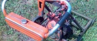
DIY assembly
Experts say that making a small-sized worm gear with your own hands is quite troublesome, but it is possible. The device should increase the torque of the working shaft of the walk-behind tractor and reduce its number of revolutions. The maximum performance of the machine directly depends on the product.
The walk-behind tractor uses a reverse manual gearbox, which makes it possible to change speeds. The factory gear ratio is sometimes very small. The designers equipped the unit with a small sprocket on the operating shaft of the gearbox.
Interacting with a large star from the wheel of the device, it ensures a decrease in engine speed. An additional sprocket must be put on the working shaft located in the bearing platform.
It will transmit torque through the second chain to the wheels of the walk-behind tractor.
Thus, you can assemble a reduction gearbox for an electric motor with your own hands, which will have high torque and a two-stage reduction in the number of engine revolutions.
Using a gearbox from any motorcycle, it becomes possible to adjust the speed without pressing the gas handle.
The engine will almost always operate at low speeds and fail less.
You can make a bevel gear with your own hands from an old scooter or tractor. In this case, the wheeled platform is not used.
It is necessary to install cultivator rollers on the bridge. This option provides optimal operating power and travel speed.
Source
How to make a reduction gearbox with your own hands: algorithm of actions
Currently, many owners of home workshops equip them with modern tools and equipment, which, being highly efficient and easy to use, significantly facilitates work and increases its productivity. However, at the same time, quite technically simple devices that can be made with your own hands in a home workshop are still in demand. One of them is a reduction gearbox.
Features of the cylindrical device
The helical gear reducer is the most common type used in mechanical engineering, metallurgy and agriculture. Straight and helical cylindrical gears are structurally simple and reliable, easy to use. Its design, if necessary, becomes more complicated, becoming reversible - for use in cars or garden equipment.
The spur gear has an efficiency of 98-99% efficiency and low heat generation. At the same time, the gears are capable of transmitting high power to the target mechanism unit.
Helical gearboxes are produced both for industry and for private purposes. You can buy a separately sold gearbox and use it on any homemade device.
The disadvantage of a cylindrical gear device is the difficulty of maintenance in comparison with chain transmissions of the same power and high noise during operation.
Preliminary preparation
Before you begin creating this device, you must have general knowledge of mechanics, be able to use repair tools and equipment, and know the operating principle and structure of this unit.
In addition, you need to initially determine:
- the type of future gearbox and its version;
- the gear ratio that will need to be converted and determined at the output;
- indicators of dynamic loads that will affect the working parts of the device;
- weight and dimensions of the future device;
- installation angle;
- temperature limits that will occur in the device during its operation;
- switching cycle – full or variable;
- intensity of operation.
More details about the components
The assembly process is not as complicated as the selection or production of spare parts necessary for such a gearbox.
- Device body. In industry it is produced by casting. The necessary holes are made using high-precision equipment, since it is necessary to achieve the mutually correct arrangement of the shafts and the alignment of the stars. When producing it, it is necessary to make the top cover removable. This will facilitate and simplify the process of servicing it during operation;
- Shafts and axles of the gearbox. They support gears and are used if they need to be equipped with this device. Installation is carried out by pressing onto splines or keys. For their manufacture, it is better to use durable steel measuring from 10 to 45 mm, which is easy to machine;
- Bearings. They are used as supports for shafts and resist loads and provide the possibility of rotational movement. Its reliability, durability and performance depend on the correct selection of these gearbox elements. If you are installing spur gears, then it will be sufficient to install conventional single or double row ball bearings. If a helical bearing or worm gear will be installed, then a roller or angular thrust ball bearing will be the best option. It is better to buy new ones than to use them from disassembly;
- Gears. They provide a change in the rotation speed of the shafts and, naturally, a reduction in the gear ratio. For their production, special metal-cutting equipment is used, which home workshops are not equipped with. The dimensions and characteristics of other parts included in this unit, as well as the distance between the axles and shafts, depend on the size of the gears. When installing, it is important to correctly set the gap between them. I-20 oil is perfect for lubricating gears. It is filled to the level of the bottom of the gears. Other parts of the device are lubricated by spraying lubricant onto them. You can take it from disassembly or buy new ones;
- Oil seals. They prevent oil from leaking out of the device body. They are installed at the exit points of the shafts on bearings under the covers. Are bought;
- Safety coupling. It is designed to prevent destruction of the device when excessive loads occur. Buyable;
- Bearing caps. They can be different - deaf and through. Designed to facilitate maintenance and installation of bearings. You can grind them yourself or find them at a disassembly site.
Design and principle of operation
A gearbox without additions, gas or hydraulic, implies a mechanical device for changing angular speed and torque. It works on the principle of the Golden Rule, when the power transmitted by rotation remains virtually unchanged and decreases by efficiency.
Device
The simplest device of a gearbox is an engagement of a pinion and a cogwheel. Torque is transmitted through direct contact of the teeth - the elements of the part. They move with the same linear speed, but different angular speed. The number of rotations of the gear and wheel per unit of time is different, depending on the diameters of the parts and the number of teeth.
Gears and wheels are fixedly mounted on shafts or manufactured together with them. The housing can have from one to several pairs of gears. The assembly drawing of the gearbox clearly shows its structure and components:
- frame;
- case cover;
- pairs in mesh;
- shafts;
- bearings;
- O-rings;
- covers.
The housing at the very bottom has a hole for draining the oil and a device for monitoring the level of lubricants, a peephole or a dipstick. The connector with the cover coincides with the plane of the axes.
The kinematic diagram of the gearbox schematically shows the gear connections, shaft locations and direction of rotation. The type of tooth, straight or oblique, is also shown. Using the kinematic diagram, you can determine the number of stages, gear ratio and other characteristics of how a given gearbox works.
Operating principle
The operating principle of a mechanical gearbox is based on the transmission of torque from one shaft to another through the interaction of gear parts fixedly mounted on them. The linear speed of the teeth is the same. It cannot be different, since the contact is hard.
The principle of operation of the gearbox is the pressure of a tooth on the surface of a similar one with an adjacent part and the transmission of force that moves the driven wheel. As a result, the rotation speed decreases. A force is created on the output shaft that can set the actuator in motion.
The main pair is always the first, a high-speed gear or worm connected to the engine and its corresponding wheel. The entire node is determined by its type. The number of stages is equal to the number of gears with a gear ratio greater than 1.
In addition to working gears, parasitic gears can be used - gears that do not change the torque, only the direction of rotation of the wheel and, accordingly, the shaft on which it is located.
Marking
The gear designation contains a number of numbers and letters indicating its parameters and type. The first is an indication of the number of steps and the type of gearing:
- cylindrical - C;
- worm - H;
- conical - K;
- globoid – G;
- wave – B;
- planetary – P.
Combined models are designated by several letters, starting with the first pair:
- cylindrical-worm - TsCh;
- worm-cylindrical – ChC;
- conical-cylindrical – KC.
The number of gears of this type is indicated by a number before the letter.
The horizontal position is considered the norm and does not have its own designation. For a vertical unit, the letter V is placed after the designation of the gear type. B - means a high-speed model. It is followed by a conventional numerical designation of the assembly option.
Next, the distance between the axes of the drive and output shafts, the gear ratio in numbers and the shape of the output shaft in letters are indicated, for example, C - cylindrical shank, K - conical.
The marking may contain an indication of the climatic version, for example, for the tropics, northern regions, and according to which standard it is fulfilled.
For example: 1Ts2U-250-31.5-22-M-U2. Two-stage cylindrical with horizontal arrangement. The center-to-center distance of the low-speed stage shafts is 250 mm, the gear ratio is 31.5. Unit assembly option 22, coupling-type shank, climatic version complies with GOST 15150-69.
Download GOST 15150-69
An electric drive - a motor and a transmission unit in one housing, has slightly different markings. At the beginning there is a letter designation of the brand of the assembled drive; the rotation speed of the output wheel is indicated, since it is constant and connected to one electric motor.
Stages of work to create this device
- Installation of drive sprockets on the input shaft. In this case, installation can be done by spot welding, flange or key connection;
- Assembly of driven shaft axles;
- Installation of the driven sprocket;
- The case can be picked up from disassembly and adjusted or made by yourself. At the same time, it is necessary to make technological holes in it for oil seals and bearing connections;
- Installation of closed type ball bearings. An excellent option would be cylindrical ones. Their installation is carried out by tension;
- The drive shaft is mounted on eccentric bearing supports with the ability to adjust the chain tension by at least 15 degrees;
- At the final stage, a lid with a sealing gasket is installed.
Having decided to do this, it is better to first assess your strengths, knowledge and skills in handling the tool, so as not to get into trouble by spending a decent amount of money, a lot of time and effort, and at the same time, without creating the necessary device, but if you are an existing or former mechanic, you can safely get down to business.
How to make a gearbox for a walk-behind tractor with your own hands
Making a gearbox for a walk-behind tractor with your own hands is a difficult and at the same time interesting task. This is one of the important mechanisms, without which the operation of garden equipment using a walk-behind tractor is unthinkable. Its main task is to reduce the speed of the drive shaft and at the same time increase or decrease the torque to the drive.
You can buy a transmission mechanism for your walk-behind tractor in a specialized store, but it is wiser to assemble the gearbox yourself, taking into account all the technical characteristics of the engine. This will be the best option, since when designing a mechanism for a specific power plant, an individual calculation is made, which will simplify the task of pairing it with the engine.
Motoblocks with gear transmission
A walk-behind tractor with a gear reducer is designed for plowing and cultivating small areas of land. Depending on the size of the plot, the power of a mechanical plow is selected, reaching 10-15 hp. With. The operation of a mechanism of such power is impossible on a belt or chain drive. After all, gears can withstand much greater loads.
A reduction gearbox installed on powerful walk-behind tractors can be made independently from spare parts of automobile differentials and gearboxes, or purchased in a store from a number of those produced for garden purposes.
or JSC "Red October - Neva", produce spur gear reducers for the transmission of Russian-assembled walk-behind tractors. These devices are produced as spare parts for cultivators, and therefore are not always interchangeable. This limits their installation on another walk-behind tractor model.
Walk-behind tractors with a gear reducer and a disc clutch have gained popularity due to gear shifting without stopping the pulley. But such designs are more complex and more expensive.
The most common are sealed gearboxes with an oil bath and an aluminum housing. Being lightweight and simple in design, such mechanisms require virtually no maintenance. There are non-separable models that, when they fail, are replaced and cannot be repaired.
Types of gearboxes
The design of any converting device for a walk-behind tractor (gearbox) consists of a set of motion-transmitting shafts or gears of different diameters, enclosed in a durable housing.
Converting devices are divided into several types according to the type of transmission:
- chain;
- belt;
- gear;
- worm (gear-worm);
- combined systems.
For chain-type gearboxes, rotation transmission is provided using a chain and sprockets of different sizes, which are installed on rotary shafts. The operating principle of a belt mechanism is similar to a chain mechanism, but instead of sprockets and a chain, pulleys and a belt are used.
Inside the housing of the gear reducer there are shafts with gears mounted on them, having straight or oblique teeth. Gears transmit rotation from the engine to moving parts. Bevel gears are used in angular mechanisms for heavy walk-behind tractors.
Walk-behind tractor design
Schemes for assembling homemade walk-behind tractors are as varied as the spare parts in each owner’s garage. Dimensions are also chosen for practical reasons.
With different compositions and dimensions, there are required elements:
- The frame is a durable structure for attaching other parts.
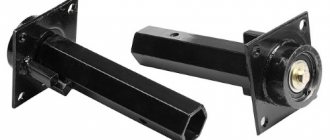
- Wheels - from homemade metal to factory-made rubber. The position of the wheel or wheelset axle is fixed relative to the frame by iron struts with pressed-in bearings.
- Engine - power from 5 to 10 horsepower. You can even use an electric motor with a battery, but the most popular are engines from a scooter or motorcycle. This choice is good because it has a ready-made speed control and even a transmission device.
- Gearbox is a unit for transmitting rotation from the engine to the actuator, converting speed and direction.
But the first gearbox you come across may not be suitable. You need to choose the type of structure, calculate the size of each part, so that the speed and power of movement of the mounted cultivator allows you to cultivate the land in a convenient mode - neither quickly nor slowly.
Types of mechanisms
According to the method of operation and action, all transforming mechanisms for walk-behind tractors are divided into several types:
- angular;
- downward;
- reverse with reverse speed (reverse gearbox);
To redirect rotational energy from a vertical drive to a horizontal plane, an angular gearbox using bevel gears (bevel gearbox) is used.
Reducing the number of revolutions and increasing the power of the drive mechanism is provided by reduction gearboxes, or creepers for the walk-behind tractor. They are considered the most reliable for operating a diesel or gasoline air-cooled walk-behind tractor. This allows them to be used for particularly difficult work - for example, plowing heavy soil or harvesting potatoes using a potato digger.
Equipment
The converter can be collapsible or non-dismountable. As a rule, budget modifications of walk-behind tractors are equipped with the latter option. Their difference is in less expensive parts that cannot be replaced. If it breaks, you will have to replace the entire gearbox. Manufacturers determine the service life of such models from one to two seasons, no more, provided that the device is used correctly.
More expensive equipment is equipped with a collapsible gearbox, which can be repaired by replacing failed components. Therefore, the service life increases significantly.
The converter package includes the following items.
- Frame . Depending on the type of gearbox, it may be dismountable or not.
- Rotor shaft , which provides torque.
- Gears of different sizes.
- Chain or belt depending on the type of gearbox.
- With chain transmission, movement is carried out using sprockets - toothed disks .
- With a belt drive, the mechanism is equipped with pulleys onto which the belt is placed.
- Bearings . Since all the parts rotate, it is necessary to reduce friction and ensure that the elements rotate freely. The bearing is designed to cope with this task.
All parts are located inside the case. In addition to the standard set of components, elements for lubricating bearings, for example, an oil pump or a cooling device, can be added inside the device.
Depending on the type of transmission used in the gearbox, converters are divided into several types. Different devices are used in mechanisms of different fields of activity.
Chain
The name is due to the design of the gearbox, which is based on a chain as a transmitting element. There may be more than one in one device. The movement is provided by sprockets, the small one is the leading one, the big one is the driven one. The principle is similar to the system on a bicycle . Productivity and reliability depend significantly on the quality of materials used to manufacture the main driving parts.
Among the negative aspects, the need for regular maintenance should be highlighted: chain tightening, lubrication. Unlike a belt drive, a chain drive does not allow slipping and lasts longer.
With reverse
The reversing mechanism provides the equipment with the ability to reverse. In this case, the reverse rotation clutch is installed between the bevel gears, which are located on the main shaft.
Unfortunately, the reverse gearbox is not suitable for reproducing high speeds.
Belt
The simplest gearbox available on the market is of the belt type. As a rule, budget gearbox models use just such a device. The belt serves as a transmission element that is attached to the pulleys. Under heavy loads, the belt slips or breaks.
Slippage can be eliminated by installing toothed pulleys and a similar belt.
Belt converters reduce the aggressive effect on the power plant, reducing jerking. In addition, their design is simple and repairs are easy.
Among the minuses, unfortunately, there are more factors.
- At high temperatures the belt stretches. This is what reduces grip.
- Rapid wear and tear.
- Belt drive rupture due to kinks or twists.
- As the speed increases, the belt begins to slip.
- The pulleys must be in the same plane.
Gear
Gear reducers are most often used in engines of heavy equipment. The transmission consists of a gearbox, differentials and regulator, gears and belts. The design of the device is simple.
A gear transmission contains bevel or spur gears. Due to the fact that several of them can be placed on one shaft at once, the dimensions of the converter are reduced.
Read also: Drilling iron with a drill on tiles
Inside the gearbox, the gears work in pairs, so the ratio of the number of teeth on the driving and driven parts must be observed. Since freedom of rotation is necessary, the gear reducer requires regular lubrication and oil.
Among the advantages, one can also highlight the quietness of the engine on this type of gearbox.
Worm
The worm gear inverter features long service life and high reliability. The design is considered not very complex and requires qualified maintenance. The worm gear is already angular. In addition, it has a reverse, which allows the equipment to move not only forward, but also backward.
The gearbox got its name from the presence of a special worm gear in its composition, which moves along a screw having a trapezoidal four- or two-start thread. By varying the number of teeth, you can change the rotational speed . All components are made of anti-friction steel, which is characterized by increased strength.
The converter consists of only two main components. In addition, it is quiet and smooth.
Users appreciate it for its efficiency and long service life. The worm gearbox has a unique ability, unique to it, not to transmit rotation from the execution device to the engine.
Angular
One of the most efficient and reliable gearboxes. Therefore, it is used to equip production machines and equipment operating under heavy loads. This type of converter is also actively used in the automotive industry.
The angular gearbox provides connection between the engine and the transmission, which is designed for a chain drive. It should be noted that the magnitude of the load will depend on the quality of lubricants and temperature conditions.
Downward
The goal of a reduction gearbox is to reduce the number of revolutions while increasing power. This is achieved by using a gear system. As a rule, modern converters of this type are equipped with an air cooling system.
Engines based on them are reliable, multifunctional and can withstand significant loads. Therefore, they are installed on walk-behind tractors used for working on heavy soils.
How to make a homemade gearbox for a walk-behind tractor
To independently assemble the converting device on a walk-behind tractor, you need to stock up on the following tools:
- calipers and metal ruler;
- a set of screwdrivers of different sizes, including an oblique one;
- pliers and wire cutters;
- metal saw;
- electric drill with a set of metal drills;
- vice;
- hammers - large and small;
- rubber gaskets.
If you decide to assemble the gearbox for your walk-behind tractor yourself, be sure to make an approximate calculation. This will help determine, at a minimum, the gear ratio and type of converter you need.
Also, using preliminary calculations, you can estimate the dimensions of the future transmission device.
To make the correct calculation, determine the parameters of your engine. For calculations it is necessary to clarify several data:
- Engine crankshaft speed. However, this value is not constant: if you “add the gas”, it will increase significantly. Therefore, calculations are based on the base - the number of idle speeds plus 10%.
- Estimated number of revolutions for the suspension axle. It is calculated taking into account the diameter of the wheels to determine the run-out per full revolution. Based on this, you can calculate at what speed the axis should rotate in order to ensure the most comfortable speed of movement of the walk-behind tractor. This is on average from 3 to 5 km/h.
Let's take a simple example: the engine power at idle, taking into account an increase of 10%, is 600 rpm, and to ensure a speed of 3 km/h, a rotation speed of 200 rpm is required. Therefore, the design gear ratio is 3:1. In other words, to reduce the rotation speed of the axle by a factor of three to ensure a travel speed of 3 km per hour, the torque increases three times.
How much oil to pour into the walk-behind tractor gearbox
When operating the walk-behind tractor, it is necessary to maintain a constant oil level in the gearbox. If this simple rule is not followed, lubricant residues may boil and jam the parts. Only high-quality oil is poured. Even with constant maintenance of the level, breakdowns occur. During chain transmission, the chain breaks or is pulled out. If traces of oil appear on the outside, this is a sign of leaking seals. Worn parts require replacement with similar ones. It is better to purchase them from a reputable manufacturer.
The gearbox ensures uninterrupted operation of the walk-behind tractor, extends its service life and increases the efficiency of use of the unit. A good helper in this matter is to lubricate its parts. Transmission oil is poured in for lubrication. Its possible brand is ZIC 10W40, Super T-3. The oil level is determined in this way:
- you need to take a wire approximately 70 cm long instead of a probe and bend it into an arc;
- insert into the filling hole until it stops;
- pull the homemade dipstick back;
- the wire should be oiled to a length of about 30 cm.
This level is considered to be the norm. If there is little oil, you need to add it to the norm. In a purchased gearbox, the level must be indicated in the instructions. A Chinese walk-behind tractor can be sold without oil.