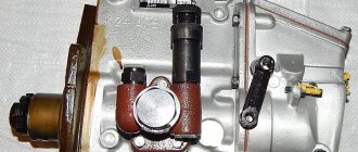
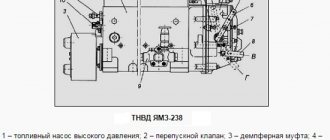
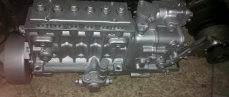
The main components and parts of the injection pump UTN-5 (high pressure fuel pump) of the D-240 MTZ 80, 82 engine are the pump body, plunger pairs, cam shaft, valves, regulator. Failure or incorrect operation of these components leads to unstable operation of the engine, the engine troits (not all cylinders work), the engine stalls, picks up speed poorly or does not pick up at all.
All these points need to be eliminated because... this can lead to breakdown of the engine itself, and this is an expensive repair. Therefore, timely maintenance and adjustment must be carried out within the time limits specified in the operating manual.
Typical fuel injection pump malfunctions
The main causes of pump malfunctions are:
- Unacceptable wear or failure of parts of plunger pairs, which entails a drop and imbalance in performance between sections. In this situation, the engine operation is unstable, especially at idle speed, and the engine power indicator also drops.
- When the sealing density of the section discharge valve in the pipeline supplying fuel to the atomizer decreases, the stability of the high pressure is disrupted, resulting in a decrease in atomization quality. Due to the appearance of fuel leakage at the end of injection, engine operation is accompanied by incomplete combustion with black exhaust. This increases fuel consumption.
An obvious malfunction of the valve can be determined by observing the edge of the section discharge valve fitting when turning the pump shaft, having first unscrewed the connecting nut of the high pressure fuel line. Considering that the operation of the valve is to pass pressure into the fuel line of the nozzle at the moment the plunger supplies fuel and locks the above-plunger cavity at the moment of the suction stroke of the pair, the level in the connecting cavity of the fitting filled with fuel should not fall when the plunger transitions from the supply stroke to the stroke of fuel suction into the above-plunger cavity . A drop in level indicates that the valve does not perform a closing function.
- Wear of the nylon mushroom-shaped valves of the booster pump and its working precision pair entails the ingress of diesel fuel into the pump body, as well as a drop in the fuel supply pressure to the sections, which reduces the performance of the injection pump. As well as the malfunction and wear of the manual pump parts, it complicates the bleeding process when removing air pockets from the system.
When air gets into the fuel, problems with starting occur, failures in engine operation appear with disruption of rotational stability in all modes. The reasons are air leaks in leaky equipment connections or lack of fuel in the tank.
- A malfunction or incorrect setting of the all-mode regulator mechanism does not ensure regulation of the amount of fuel supplied by the sections in accordance with the operating modes and loads acting on the diesel engine. The problem entails a drop in power and excessive fuel consumption.
- Wear on the cam shaft and its support bearings, tappets, rotary ring teeth and rack leads to unbalanced fuel delivery.
Fuel injection pump malfunctions at MTZ and their causes
One of the main malfunctions of the MTZ injection pump is wear of the plunger pair. Due to friction, the working surfaces of the plunger and sleeve are actuated. This wear occurs due to small solid particles that are found in the fuel. The presence of a large amount of sulfur in the fuel also leads to increased wear. Worn plunger pairs are replaced with new ones or restored. Change filters in a timely manner. The entire fuel system, especially the injection pump, is very afraid of the presence of water in the fuel. Because of this, water hammer occurs in the plunger pairs, which leads to the destruction of pump parts. These are the main malfunctions and their causes.
Characteristics of fuel injection pump
The MTZ fuel pump belongs to the category of four-plunger units and is designed to ensure the necessary fuel circulation. In the design of the tractor, it is located in one block with a pumping analogue and a centrifugal regulator. The block is located on the left side of the D-240 engine, secured with bolts to the distribution cover.
Before you figure out how to add fuel to the MTZ injection pump, you need to become more familiar with its characteristics and features. Correct operation of the unit is ensured by the action of the crankshaft, which drives it through a gear mechanism.
MTZ tractor fuel pump
Among the most significant characteristics of this important element it is advisable to include:
- manufacturer - Noginsk;
- spare parts catalog number - 4UTNI-1111005-20;
- scope of application - power units of the D series (from 240 to 248.1 modification) for various MTZ models;
- drive type - splined bushing.
The MTZ 82 fuel equipment is not a completely unique development, since it has foreign analogues. An example is the Czech-made PP4M9P1g-4201, which is almost identical in its technical design and characteristics.
Related Posts
Why, after replacing the injection pump, did the engine on the MTZ 82 begin to overheat? The gasket was broken - they replaced it, reset the ignition, adjusted the valves. The problem remained.
- Author: Firdus Gelmutdinov
- October 02, 2020
Good afternoon !
After replacing the injection pump, the engine on the MTZ 82 began to overheat, such problems had not been observed before, has anyone encountered this? After two months of operation, at temperatures closer to 100 degrees, the cylinder head gasket blew, we replaced it, changed the ignition, adjusted the valves, but the problem still remained! The radiator itself is clean, but aluminum, there seems to be circulation! They advise installing a fan with 6 blades instead of 4, and installing a diffuser, but I think this will not solve the problem, it heats up even without much load in about 30 minutes of operation! Thanks in advance for the answers. MTZ MTZ 82 Cylinder head gasket breaks Replacement Ignition Set valves Adjust Adjustment Injection pump problem Why Engine overheating
Write a comment
In this case, the rack moves in the direction of increasing fuel supply. Above the sleeve 5 there is a discharge valve 4 with a seat valve 3 and a spring 1.
The injection pressure and the tightness of the injectors can be determined without removing them from the diesel engine. Remove some of the fuel from the momentoscope tube.
When the bolt is loosened, the performance and throughput of the pump decreases proportionally, and when tightened, on the contrary, it increases.
I increase the parameters and get back into the tractor.
If, according to the measurements, the difference is greater, then we adjust the corresponding section.
Careful attention is paid to this process, since in the event of a malfunction, diesel fuel will be driven into the oil pan. This wear occurs due to small solid particles that are found in the fuel.
Fuel pump UTN how I adjusted the injection pump myself on MTZ 82/its work
See also: Suspended on MTZ-82
Tell me how to reduce fuel consumption on MTZ-82.1
Good day everyone. Tell me how to reduce fuel consumption on an MTZ-82.1, 4UTNI pump, engine D-243, 2011 tractor. I work clearing snow, I fill up 40 liters - it only lasts for 5-6 hours. The old tractor ate 2 times less with the same work. What could be the matter?
remove the fuel and check the injectors on a stand
Is the air filter clean?
and how would you like it, under load, for the tractor to be fed with air? 40l in 5-6 hours is normal
and how would you like it, under load, for the tractor to be fed with air? 40l in 5-6 hours is normal
IN OUR ORGANIZATION WE JUST HAVE 2 MORE OLD MTZ WITH 240 ENGINES SO 20L IS ENOUGH FOR THE ENTIRE DAY (8 HOURS) WE DRIVE THE SAME WITH THE SAME KNIVES AND I CAN’T STAY IN 40.
and how would you like it, under load, for the tractor to be fed with air? 40l in 5-6 hours is normal
The man says that the old one ate less at the same job.
Is there any black smoke? How does it start? Works? Most likely it is indeed a fuel equipment.
Is the air filter clean?
BY THE WAY ABOUT THE FILTER. WHEN I REMOVED THE PAN AFTER BREAKING IN, THERE WAS A PIECE OF POLYETHYLENE AND SOME ROPE FLOATING IN THE OIL, IT CAME FROM THE FACTORY, THE ENGINE WORKED INTERMITTENTLY AND VERY HARD. AFTER WASHING THE FILTER THE INTERRUPTIONS HAD GONE BUT HARD WORK STAYED, SO I THINK MAYBE SOMETHING IN THE COLLECTOR IT'S SUCKS, THAT'S WHY THE CONSUMPTION IS LIKE THIS?
Is there any black smoke? How does it start? Works? Most likely it is indeed a fuel equipment.
NO SMOKE AT ALL, ONLY UNDER A LIGHT LOAD, STARTS GOOD, BUT RUNS HARD WITH THE OLD CAN’T COMPARE
remove the fuel and check the injectors on a stand
So I tell my mechanic this, but he resists, citing the fact that the tractor is new and everything is already adjusted at the factory. But my norm on it is 32 liters. For 8 hours I have to add hours to the trip in order to write off the diesel fuel
7-8 liters per hour is normal consumption when operating under load. Another thing is that your old tractors have worn-out equipment and do not pump as much fuel, but even under load they will not pull. Because of this, they work softer - even increasing the injection pressure leads to harsher engine operation. I have a Southern excavator that worked for more than fifteen years on fuel without repair - it only sniffed diesel fuel, but it didn’t carry any luck, in the mud even on the first one it withered and stalled (although when I took it from the fence on the third one it easily overcame any dirt) after repairing the fuel pump, the starting started from half a turn, the traction returned, I didn’t even believe it myself - in the same fields in the mud, third became the running gear - but the appetite also increased. In order for the horses to run, they need to be fed not only with air and a whip, but also with oats (here diesel fuel for the tractor).
7-8 liters per hour is normal consumption when operating under load. Another thing is that your old tractors have worn-out equipment and do not pump as much fuel, but even under load they will not pull. Because of this, they work softer - even increasing the injection pressure leads to harsher engine operation. I have a Southern excavator that worked for more than fifteen years on fuel without repair - it only sniffed diesel fuel, but it didn’t carry any luck, in the mud even on the first one it withered and stalled (although when I took it from the fence on the third one it easily overcame any dirt) after repairing the fuel pump, the starting started from half a turn, the traction returned, I didn’t even believe it myself - in the same fields in the mud, third became the running gear - but the appetite also increased. In order for the horses to run, they need to be fed not only with air and a whip, but also with oats (here diesel fuel for the tractor).
I agree, it means that the standard is coming out, you need to ask for another one if everything turns out to be in order with the fuel system?
Is there any black smoke? How does it start? Works? Most likely it is indeed a fuel equipment.
NO SMOKE AT ALL, ONLY UNDER A LIGHT LOAD, STARTS GOOD, BUT RUNS HARD WITH THE OLD CAN’T COMPARE
They all work like that when they’re new. For what reason, who knows? But your consumption is normal, which, believe me, isn’t much at all. If you have a dispute with a mechanic, shove your passport data in his face. And you shouldn’t open the pump if the tractor is under warranty. Then you’ll rake it yourself.
7-8 liters per hour is normal consumption when operating under load. Another thing is that your old tractors have worn-out equipment and do not pump as much fuel, but even under load they will not pull. Because of this, they work softer - even increasing the injection pressure leads to harsher engine operation. I have a Southern excavator that worked for more than fifteen years on fuel without repair - it only sniffed diesel fuel, but it didn’t carry any luck, in the mud even on the first one it withered and stalled (although when I took it from the fence on the third one it easily overcame any dirt) after repairing the fuel pump, the starting started from half a turn, the traction returned, I didn’t even believe it myself - in the same fields in the mud, third became the running gear - but the appetite also increased. In order for the horses to run, they need to be fed not only with air and a whip, but also with oats (here diesel fuel for the tractor).
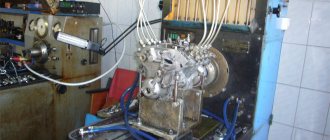
Diagnostics and complete adjustment of fuel injection pump
A full check and subsequent adjustment of the fuel pump is carried out on a special stand, which allows you to:
- Pump drive with variable speed within the operating modes of the engine
- Pump cycle counter with automatic drive shutdown
- Device for measuring the injection start angle of a section
- Volumetric flasks for collecting fuel while monitoring the performance of each section in a given mode
Checking the pressure in the section
This operation determines the technical condition of the section. The check is carried out with a pressure gauge installed on the section fitting. By manually turning the injection pump shaft, fuel is pumped into the device line. After pumping for two cycles, the pressure gauge will show the pressure created by the section. The indicator of a plunger pair suitable for operation must be at least 350 kg/cmᶾ(35 mPa). In this case, the discharge valve must hold the created pressure for at least 10 seconds, confirming the tightness of closure. If the experimental readings are lower than the above, the corresponding pairs of parts must be replaced.
Pressure gauge for pump section diagnostics
And also to check the condition of the plunger pair, use a test nozzle adjusted to trigger the injection at 30 mPa (300 kg/cmᶾ). The device is used both to test the pump on a stand and directly on the tractor, creating the nominal speed. If the section pressure is not enough for the injector to fully operate, the unit is sent for repair.
If the pump sections meet the technical test criteria, the unit is fully configured for further operation.
Setting the nominal fuel supply
Adjustment is carried out by changing the length of the “nominal” bolt located in the rear wall of the pump regulator. The position of the bolt limits the stroke of the main rod in the direction of increasing fuel supply and determines the hourly performance of the pump.
It is this adjustment that answers the question of tractor drivers “how to reduce or increase the fuel supply at the tractor fuel pump?”
The setting is carried out as follows:
- The control lever 13 is set to the maximum feed position
- The lock nut of bolt 6 of the nominal feed is unscrewed
- Rail 1 is recessed as much as possible into its extreme forward position
- The adjusting bolt is screwed in until it stops, holding the rack
- Then unscrew 6 one turn, ensuring the movement of levers 7 and 8, and fix the position with a lock nut. In this case, the overhang of the rack 1 from the inner wall of the housing to its end, in the state of the recessed corrector rod 5, should be within 24-24.5 mm, and the amplitude of the rack stroke should provide the full range of changes in the fuel supply by the pump.
Thus, the nominal fuel supply is established in all operating modes of the regulator.
UTN regulator diagram
Preliminary check of uniformity of fuel supply by sections
High pressure fuel lines are connected to the pump section to drain fuel into separate volumetric flasks. The check is done at 600 pump shaft speeds per minute for 1000 cycles of operation of the plunger pair. Experience shows the productivity and uniformity of fuel supply by sections. If there are no obvious discrepancies in the performance of individual sections, continue to the next stage of tuning.
To fully understand the process of setting up and testing the injection pump, you need to understand that one revolution of the pump shaft is equivalent to two revolutions of the crankshaft, taking into account the four-stroke operation of a diesel engine.
Checking and setting maximum diesel speed
This setting changes the maximum rotation speed limit. The test is carried out at a pump shaft speed of 1115 rpm with a gradual increase at maximum flow. In this case, observation is recorded at what speed the regulator operates, limiting the engine rotation speed by reducing the fuel supply. The normal limit of the rack output moment for pumps 4 UTNI, 4 UTNM, UTN 5 of the MTZ 80(82) tractor should be within 1115-1125 rpm. pump shaft.
If there is a need to adjust the actuation moment, the adjustment is made with a bolt of 12 “maximum revolutions” screwed into the boss of the regulator body, which limits the rotation of the control lever. To increase the engine speed at which the regulator will operate, the bolt is unscrewed, and to decrease it, screwed in. One turn of the adjusting bolt corresponds to a frequency change of 30-50 rpm. If it is not possible to achieve the correct adjustment by rotating bolt 12, then the adjustment is made by changing the tension of the spring 3 of the regulator by rearranging the earring on the coils of the part.
Setting the uniformity of fuel supply by sections
The performance of a separate section is checked at a nominal pump speed of 1100 rpm. corresponding to the nominal speed of the diesel engine with 1000 cycles of plunger pairs. Tabular readings of the performance of each individual pair, according to the technical requirements of the manufacturer for the MTZ 80(82) tractor with the D-240 engine, must correspond to a volume of 70 cmᶾ per 1000 cycles (70 mmᶾ per cycle) with a permissible discrepancy in section readings of no more than 3%.
If the indicator does not match the tabular data, performance adjustments are made in individual sections. The adjustment is carried out by changing the position of the rotary sleeve in the section, thereby changing the position of the plunger and its discharge groove. To make adjustments, the tightening screws of the ring gears are released. When turning the liner to the left relative to the section crown, the fuel supply increases, and to the right, it decreases. A repeat check confirms the success of the adjustment. Thus, the amount of fuel supplied by an individual plunger changes.
Setting the injection start angle in fuel injection pump sections
In accordance with the tabulated data of the fuel supply start angle of 57˚, the injection start angles are adjusted in separate sections, which correspond to the angles of rotation of the pump shaft: in the first section 49˚, in the second 139˚, the third 319˚ and the fourth 229˚. The test is carried out at a nominal speed of 1100 rpm. Steady-state readings of the device are recorded for 500 operating cycles. Determine the actual data in each section one by one.
If the injection angle does not coincide with the tabular data, adjustment is carried out by changing the length of the pusher adjusting bolt. To do this, loosen the control nut of the bolt with a 14 wrench, and if necessary, reduce the injection angle, shorten the pusher by tightening the bolt with a 17 wrench. To increase the angle, lengthen the pusher by turning out the bolt. Finally, tighten the locknut, fixing the length of the pusher. Then the angle check is repeated and, if necessary, adjustment is carried out followed by checking to the desired value.
Adjustment in overload mode
The goal is to adjust the operation of the corrector in overload mode at 850 rpm of the pump. According to the tabular data, the automatic increase in fuel supply by sections from the nominal value (70 mmᶾ/cycle) should be within 15 -22%. Thus, the result of correct operation of the corrector during overload is an increase in feed in each section to a volume ranging from 79 to 83 cmᶾ for 1000 working cycles (79 – 83 mmᶾ/cycle). If the bench test shows an insufficient correction percentage, then the change in performance is adjusted by increasing the stroke length of the corrector rod.
The tabulated degree of correction is established by observing the design dimensions of the rod stroke when assembling the corrector. The rod stroke should be 1.3-1.5 mm. The change in the length of the rod 17 exiting the device body is controlled by washers that are installed in the corrector body. In the case of early operation of the corrector (below 1040 rpm), in which the rod is completely sunk, increase the force 7 of the spring in the device body, tightening the pressure screw 8 one or two clicks. In the opposite situation, the screw is turned out, weakening the spring force acting on the corrector rod.
Adjusting the cutoff of fuel supply to the injectors
The adjustment is carried out by positioning the “stop bolt” 18, which is located in the rear wall of the regulator above the nominal feed adjustment bolt 19. The feed stop is set at 1210 rpm. To do this, loosen the control nut of the bolt and turn it out to the level of the plane of the inner wall of the regulator body. At the set speed, turn the screw until it touches the main rod 23 of the regulator. Having determined the moment of contact, the bolt is unscrewed one turn and the position is secured with a lock nut.
Checking the fuel supply at maximum idle speed
Set the feed lever to the idle position and fix the performance at a rotation speed of 1160 rpm. In this mode, the feed of each section for MTZ 80 should not exceed for UTN 5 -27 cmᶾ, for 4 UTN 22.5 cmᶾ for 1000 operating cycles.
Checking fuel supply at minimum idle speed
The essence of the test is to determine the response of the regulator when changing the minimum idle speed. The check is carried out in three stages:
- set the productivity of the sections at idle speed at 300 rpm.
- determine the fuel supply in sections, increasing the speed by 50 revolutions (350 rpm)
- set the feed amount when reducing the rotation speed by 50 rpm (250 rpm).
The result of normal operation of the regulator at idle should be an increase in productivity in sections by 10% as the speed decreases and a decrease in productivity by 10% as the rotation speed increases from the performance reading at an idle speed of 300 rpm.
The lack of correct response of the regulator indicates the need to replace the main spring of the device. The reason is the lack of interturn gap in the spring necessary to change the supply in the minimum fuel supply position.
Checking the Feed Setting in Startup Mode
The lever is set to the maximum flow position and at 150 rpm the performance of the sections is determined for 60 cycles of pump operation. The normal fuel supply to the section in the starting mode should be no less than 14.5 cmᶾ/100 cycle (145 mmᶾ/cycle). If the indicator in this test exceeds the tabulated data, this indicates good compression of the plunger pairs, as well as a high working life of the fuel injection pump.
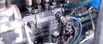
The process of adjusting the injection pump
Having made sure that all the components specified in the paragraph are in working order, we proceed to adjusting the pump itself. Since our article is called “self-adjustment,” we will adjust the pump without removing it from the engine.
Fig.1
The peculiarity of adjusting such a pump is that the adjusting bolts are located on the regulator body and inside the pump itself. Bolt-23 (Fig. 1) regulates the maximum engine speed. By twisting and unscrewing it, you increase or decrease them accordingly. Engine idle speed is adjusted by increasing or decreasing the fuel supply to the injectors per stroke of the plunger. The adjustment is carried out using a bolt of nominal value 17 (Fig. 1). When the bolt is tightened, the amount of fuel increases, and when unscrewed, it decreases; accordingly, the engine speed increases or decreases. Engine idle speed should be minimal but stable. The uniformity of fuel supply to each section is also regulated. The uniformity of the feed is regulated by turning the sleeve of the plunger pair-11 (Fig. 2). This adjustment is carried out on special stands. This is one of the main characteristics of the pump. The uniformity of feeding can be adjusted independently. To do this, you need a measuring container with the lowest possible division value (for more accurate data), a well-charged battery, and an assistant. We unscrew all the injectors so that the engine starts (and it will be easier for the battery). We connect the nozzle to the first section of the pump. We insert it into the measuring container so that as little fuel as possible goes beyond its limits (it’s better that it doesn’t go at all). We crank the engine with the battery and count the number of injections that the injector made (the more, the better the difference will be visible). We perform this operation with each section. The difference between sections should not exceed 6%. If, according to the measurements, the difference is greater, then we adjust the corresponding section. Remove the side cover of the pump. We release the coupling screw-15 (Fig. 2) and very carefully turn the rotary sleeve by pointing a screwdriver at it and slowly tapping it. Depending on the fact that we need to increase or decrease the amount of fuel, then by turning the sleeve to the left we increase the amount, and by turning it to the right we decrease it. Tighten the coupling screw-15 (Fig. 2). After this, we check again using a measuring container. We adjust until we achieve the desired indicator. We just replaced the stand with our engine, since it imitates an engine, it just has more instruments. But if there is no access to such a stand, then this method will effectively replace it. It is also necessary to check the fuel injection start angle using a torque scope. Don't be intimidated; it's easy to do it yourself. Take a piece of fuel pipe with a nut at one end (to screw it to the pump section), put a piece of transparent hose on it - the momentoscope is ready. We connect it to the first section of the pump. We turn the engine as it rotates until fuel appears in the hose. We turn it further until the fuel stops rising. There is an installation bolt on the flywheel housing, and a hole (mark) on the flywheel itself. We unscrew the bolt and make sure that the hole from the bolt coincides with the hole in the flywheel. This parameter can be adjusted using the pusher bolt-5 (Fig. 1). To decrease the angle, unscrew the bolt, to increase it, tighten it. Don't forget to secure it with a locknut.
Device
When planning to repair the MTZ fuel injection pump, you should familiarize yourself in more detail with the design of such an element. It is distinguished by a minimum number of elements and high reliability, which makes it possible to significantly simplify the procedure for adjusting the pump, as well as troubleshooting. The main components of this unit are:
- plunger pairs;
- frame;
- pressure type valve;
- pushers;
- camshaft;
- plunger drive mechanism.
The pump head and housing are a single element made of high-strength aluminum alloy. The design of the unit provides that a special plate is placed on the front part of the housing, which is used to mount the product directly on the engine. When figuring out how to remove the injection pump from the MTZ 82, it should be noted that to do this it is enough to remove the mounting bolts.
The back of the plate is equipped with a special flange, which is used to install the regulator. The principle of operation of the product is extremely simple, it involves the following algorithm of actions:
- The cam shaft begins to rotate, lifting the pusher with the help of a roller.
- The pusher moves down together with the plunger.
- Fuel fills the space in the sleeve vacated by the descent of the plunger.
- When the element returns to its original state, pressure is created, due to which, with the help of a valve, a portion of fuel flows through the nozzles.
This cycle is repeated at certain intervals, which allows you to maintain the fuel level necessary for proper engine operation.
Fuel pump diagram
Injection pump for the MTZ-80 tractor, adjustment and repair diagram
The purpose of the injection pump is to move diesel fuel from the tank to the engine cylinders. The main components of the power supply system are two tanks for diesel fuel, coarse and fine fuel filters, and a high-pressure fuel pump - injection pump. The power supply system for Belarus equipment is relatively elementary, has a classic appearance and operating principle. Having studied it well and understood the device at a theoretical level, you can safely carry out repairs yourself. The fuel system of this tractor contains about seventy parts, which is not enough for such equipment.
Design of the injection pump of the MTZ 80 tractor
The tractor pump for MTZ 80 is called UTN-5. It is made of reliable aluminum alloy. And they are produced in different mounting variations; there are left and right versions. This depends on the design and properties of the fastener. Along the entire length of the body it is divided into two cavities. This happens thanks to the partition. At the bottom there is a shaft with a pump drive, and at the top there are the component sections of this pump.
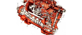
We will consider the detailed design of the injection pump of the D-240 engine further. A fuel pump with a control mechanism has the following elements: pressure fitting, discharge valve, valve seat, plunger and corresponding bushing, rotary bushing, ring with teeth, rack rod, regulator cover, corrector body, corrector rod, regulator body, heel, weight axles , heel and lever, coupling, adjuster weights, weight hub, shock absorber block, bearing cup, oil deflector, shaft with cam, plug, pump mounting flange for inflating, mounting plate, splined bushing, installation flange, roller tappet, lower spring plate, rack with gear, fuel outlet channels, bypass valve body, diesel supply hole, ball valve, fuel channels, shut-off hole, pin, plunger bushing inlet hole, manhole cover. Like any pump, the injection pump in its design has washers, clamps, main and auxiliary levers, bolts for various purposes, ball bearings, springs, plugs, nuts, gaskets, fuel transfer tubes, various screws for tightening and adjustment. There is no pump in nature without a housing and an oil hole, and there are no pumps without an eccentric for pumping fuel.
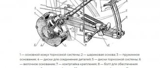
Diagram of a fuel pump with regulator
The fuel system of a diesel engine includes: an air cleaner, a muffler, an air filter, an electric torch heater with a fuel tank, an intake manifold, various pipes - drainage and high pressure, a throat for filling fuel, fuel tanks, a drain valve, fine and coarse filters for diesel fuel, fuel pump regulator, booster pump, fuel pump, injectors, exhaust manifold, filter devices for various purposes.
At the highest point of UTN-5 there are longitudinal channels connecting it to a fine filter and to the pumping system of the pump, which has a built-in bypass valve.
Description of the method of action of UTN - 5
The booster pump is attached to the main pump housing. A fuel line is connected to the fittings, through which fuel is supplied to the injectors under high pressure. The pump is driven by the crankshaft gear. If the pump has already been repaired, then after the next assembly and disassembly it is necessary to carefully check the angle of the gear connections. Otherwise, if tilted incorrectly, there will be interruptions in performance. The degree of inclination must be strictly 22°30″. It is better to check it by contacting an experienced mechanic.
Checking and adjusting the pump
Before starting, you need to make sure that the locking cone fits tightly and that the pressure of the pump section is normal. Rotate the crankshaft and move the regulator until the arrow on the pressure gauge shows 15 MPa. The engine is then turned off and the fuel supply is stopped using the control lever. If the pressure on the pressure gauge drops within ten seconds, the valve is good.
To adjust the exact angle of the moment of fuel entry, you need to turn the adjusting bolt in different directions. One turn reduces or increases crankshaft speed by approximately 40 revolutions. Unscrewing the bolt reduces the power of the pump; tightening it increases it.
Technical Tips
Logically, it can be calculated that by increasing the amount of fuel supplied to the combustion chamber, the torque also increases. And this increases engine power and speed.
Changing the engine oil in the UTN-5 device is necessary only after dismantling and repair work. This should not be done during normal operation. Only 150-200 milliliters of engine oil is required; filling is carried out through the injection pump crankcase.
Injection pump device for MTZ - 80, 82
UTN-5, as the fuel pump for the Belarusian brand of tractors is called, is made of durable aluminum alloy and is available in two possible installation options - left and right, depending on the design features of the flange mounting. Throughout the entire body, it is divided into two cavity parts by a special partition, where in the lower cavity there is a shaft with a pump drive, and in the upper cavity there are separate sections of this pump.
You can read the full detailed structure of the high pressure fuel pump of the D-240 engine below
Fuel pump with regulator:
1 - pressure fitting; 2 - clamps; 3 - spring; 4 - discharge valve; 5 — valve seat; 6 - gasket; 7 — plunger bushing; 8 - plunger; 9 - plug; 10 — ring gear; 11 — rotary sleeve; 12 — regulator cover; 13 — rack rod; 14 — spring lever; 15 — regulator spring; 16 — enrichment spring; 17 — main lever; 18 — corrector housing; 19 — corrector rod; 20 — adjusting screw; 21 - intermediate lever; 22 — nominal bolt; 23 - bolt; 24 — regulator body; 25 — load axis; 26 - heel; 27 - coupling; 28 — heel axis; 29 — lever axis; 30 — regulator weights; 31 — thrust ball bearings; 32 — drain plug; 33 — cargo hub; 34 — shock absorber block; 35 — washer; 36 — bearing cup; 37 — oil deflector; 38 — control lever; 39 - cam shaft; 40 - plug; 41 — eccentric drive of the booster pump; 42 — flange for mounting the booster pump; 43 — adjusting washer; 44 — mounting plate; 45 — pump housing; 46 — oil supply hole; 47 — roller nut; 48 — splined bushing; 49 — mounting flange; 50 — pusher with roller; 51 — pusher adjusting bolt; 52 — spring plate (lower); 53 — plunger spring; 54 — spring plate; 55 — rack; 56 — bolt for bleeding; 57 — channel for fuel removal; 58 — bypass tube; 59 — bypass valve body; 60 - plug; 61 — valve ball; 62 — hole for fuel supply; 63 — channel for fuel supply; 64 - cut-off hole; 65 — inlet hole of the plunger sleeve; 66 - pin; 67 — hatch cover; 68 — adjusting screw; 69 — gasket; 70 - filler plug; 71 — adjusting screw; 72 — corrector spring; 73 - tightening screw.
Here you can see the entire fuel system of the Belarusian tractor:
Diesel power system (diagram):
1 — muffler; 2 — air cleaner; 3 — coarse air filter; 4 — intake manifold; 5 — electric torch heater; 6 — fuel tank of the electric torch heater; 7 - drainage tube; 8 — high pressure tube; 9 — filler neck; 10 — fuel tanks; 11 - drain valve; 12 — fuel pipe; 13 — fuel coarse filter; 14 — fine fuel filter; 15 — tube from the fine filter to the fuel pump; 16 — tube from the sediment filter to the fuel pump; 17 — fuel pump regulator; 18 — fuel pipe from the booster pump to the fine filter; 19 — booster pump; 20 — bypass tube; 21 - fuel pump; 22 — nozzle; 23 — exhaust manifold; 24 - lower filter element; 25 - middle filter element; 26 - upper filter element.
At the upper cavity point of the UTN - 5 D-240 engines there are two longitudinal channels that form a square, one end of which is connected to the fine fuel filter, and the other, respectively, to the pump itself in the pump, where a bypass valve is mounted in the fitting.
Adjusting the fuel pump
One of the most important measures for servicing the fuel pump of the MTZ tractor is its adjustment. If it is performed correctly, the owner of the equipment will be able to avoid damage to the pump and other structural elements. Adjustment manipulations are carried out using a special stand, as well as the necessary tools:
- instruments that allow you to measure shaft rotation speed;
- disk for determining fuel supply;
- measuring containers for controlling fuel volumes;
- drive and variator, which are capable of smoothly changing rotation speed.
Speed indicators are adjusted using a bolt located in the product body, which is responsible for the degree of tension of the control spring. Screwing in the bolt leads to an increase in performance, and unscrewing it counterclockwise, on the contrary, will reduce the speed. The fuel supply is adjusted using a special sleeve, which works on a similar principle. For uniform feeding, you should use the nominal edge, which is also located on the body.
Trouble-shooting
There are several of the most common malfunctions that owners of MTZ tractors most often encounter. Since the price of the fuel pump is low, the technician can completely replace it if desired, but it will be much more economical to fix the breakdowns on his own.
The most common breakdown is wear of a pair of plungers , which is due to the low quality of the fuel and the abundance of impurities in it. For repairs, you will need to restore or replace damaged elements. To avoid damage, the fuel filter should be cleaned and replaced regularly.
Water hammer often leads to breakdowns due to the appearance of water in the system. If a problem occurs, you will need to thoroughly clean the element from any remaining moisture, and then restore its tightness.
Adjusting the MTZ 80 fuel pump at home
If you want to adjust the operating parameters of the injection pump at home, you need to understand that without precise measuring instruments it is impossible to carry out a complete adjustment. It is impossible to maintain adjustments in all operating modes using a makeshift method, much less compare them with the tabulated values established by the manufacturer. If you understand that the pump’s operation is unsatisfactory, it is advisable to know the condition of the unit and carry out basic diagnostics. First of all, measure the supply pressure in sections. If the indicators are insufficient, all adjustments become meaningless.
If you nevertheless dare to carry out the adjustment, be sure to record the sequence of your actions and the results obtained on paper so that you can return to the starting position in the event of a negative adjustment result.
Before starting any actions, check that the rack moves smoothly throughout the entire range of regulation and that the regulation levers move without jamming. And also check the above-described design dimensions in the operation of the regulator: stroke of the corrector rod 1.3-1.5 mm; rack offset 24.5 mm; the distance between the centers of the mounting axes of the main and intermediate rod drives is 16mm. Perhaps eliminating inconsistencies in the regulator will remove a number of negative factors in the operation of the injection pump.
Possible do-it-yourself injection pump settings
- A general decrease or increase in the amount of fuel supplied by adjusting the position of the nominal supply bolt.
- Setting the maximum speed threshold with a bolt that limits the maximum rotation of the fuel supply lever on the pump. To increase it, turn the bolt out, to decrease it, turn it in. When fixing the speed, rely on the readings of the standard tachometer.
- By adjusting the thrust bolt, above the nominal supply bolt, set the speed of stopping the fuel supply to the injectors, also observing the speed readings in the cabin.
- Perhaps try to equalize the feed across sections. For adjustment, the most difficult thing will be to determine the performance of each individual section. Then track the difference and adjust those lagging in performance to those leading or, conversely, depending on the actual hourly fuel consumption. If the flow rate is too high, then the sections with higher productivity should be equalized with lower readings, and vice versa if the hourly flow rate is reduced.
Since it is impossible to determine productivity without a cycle counter, the accuracy of the determination should be based on the criterion of equal pump shaft speeds and equal periods of time when checking each section. The pump drive, determining the performance, must rotate the shaft at a speed of 1100 rpm. When deciding to adjust the injection pump in this way, you need to be aware that the adjustment will be intuitive with very approximate accuracy.
This article describes the complete process of setting up a UTN-type injection pump technology with a mechanical all-mode regulator. The basis is taken from the tabular data for the D-240 engine of the MTZ 80(82) tractor. When setting up pumps for other engine modifications of tractor models, the adjustment is carried out based on the technical parameters of the fuel system established by the machine manufacturer.