Pramotronik is a modern domestic pre-heater that is not inferior in its characteristics to foreign analogues, however, this does not exclude the possibility of its breakdown.
In this article we will look at all possible malfunctions and errors of Pramotronic car engine preheaters.
Attention! When operating and repairing railways, it is necessary to strictly observe safety regulations and take measures to prevent the possibility of a fire.
Causes of malfunctions of the Pramotronik stove
Among the most common are:
- Debris entering the ventilation system or working boiler: small leaves, twigs, etc.
- Overheating of the heat exchanger working chamber. It is provoked by disturbances in the air circulation system.
- Voltage surges in the on-board system. The system receives the wrong voltage and the module locks automatically.
- Fuel supply problems. Fuel may be supplied in the wrong quantity or run out completely.
- System failures can occur due to natural wear and tear of the unit or incorrect operation of the remote control.
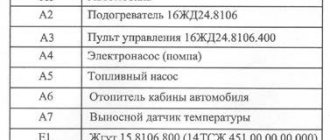
Pramotronik 12ZhD 24
The liquid heater in modification 8106 is equipped with visual indicators indicating the presence of problems in the system. It is possible to read breakdowns through a special scanner. The errors are listed below.
| Fault code | Description |
| 01 | The battery voltage is outside the specified limits. |
| 02 | More than two unsuccessful startup attempts have been made in a row. |
| 03 | The flame in the combustion chamber is interrupted. The burner is not working correctly. |
| 04 | The electric pump is malfunctioning. |
| 05 | The fuel pump is damaged. Fuel enters the working chamber inconsistently. |
| 06 | Ambient temperature sensor - open circuit or incorrect data. |
| 07 | The blower motor is not functioning correctly. |
| 08 | You need to check the spark plug. |
| 09 | Lost connection with the remote control. You need to check the cables. |
| 10 | The inlet temperature sensor is not working properly. |
| 11 | A similar problem with the outgoing stream. |
| 13 | The heat exchanger is overheated; additional radiator purging is needed. |
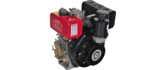
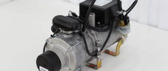
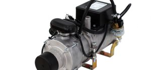
Design and operation of the pre-heater PZD-30.
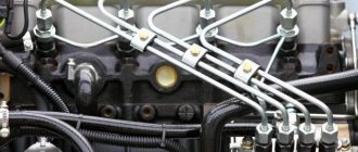
The pre-heater is designed to heat the liquid in the cooling system and the oil in the engine crankcase before starting it in cold weather. The heater consists of a heat exchanger boiler assembled with a burner, a pump unit, an electric spark ignition system, and a remote control system for the heater. The heat exchanger of the heater consists of two interconnected cavities: a liquid cavity and a gas duct. The pump unit consists of a liquid pump, an air blower (fan) and a fuel pump, driven by a single electric motor. The centrifugal type liquid pump is designed to circulate coolant between the heater and the engine. The fan is designed to supply air to the burner. The gear type fuel pump is designed to supply fuel under pressure to the heater nozzle. The electric spark ignition system is designed to create a spark discharge in the burner when starting the heater. It consists of a spark plug, a transistor switch with an ignition coil. The remote control system consists of a control switch, a contactor and connecting wires.
The heater is activated by a control switch, which has four positions:
0 - everything is turned off;
I - the electric motor of the pump unit, the electromagnetic fuel valve and the electric spark plug are turned on;
II - the electric motor of the pump unit and the electromagnetic fuel valve are turned on;
III - the electric motor of the pump unit is turned on (purge mode).
The electric fuel heater is activated by a push-button switch.
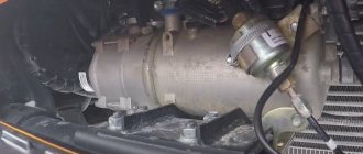
The heater works as follows. The heater fuel pump supplies fuel from the tank, which is supplied to the nozzle through an open solenoid valve and injected into the internal cavity of the heat exchanger burner. The atomized fuel is mixed with the air supplied by the fan, ignites and burns, heating the coolant in the heat exchanger. The products of fuel combustion are directed through a pipe under the engine oil sump and heat the oil in it.
The fuel is cleaned by filters installed in the solenoid valve and injector.
Fuel for the heater comes from a special fuel tank, which is filled automatically when the engine is running. When the engine is not running, the tank can be filled using a manual fuel priming pump.
Fuel consumption is regulated using a pressure reducing valve located on the fuel pump. When operating the preheater, you must ensure that there are no leaks of coolant and fuel in the connections of the fuel pipes, hoses and taps. The connections between the fuel pipes and the heater must be sealed, since air leaks into the power system are not allowed. The presence of air or a leak in the fuel supply system of the heater leads to unreliable operation and random stoppage of the heater.
Operating the heater with an open flame at the outlet is unacceptable.
Normal operation of the heater is determined by a uniform hum in the heat exchanger and the release of exhaust gases without smoke or open flame. If necessary, it is necessary to adjust the fuel consumption using the pressure reducing valve of the fuel pump, for which you must do the following:
- Unscrew the cap nut on the fuel pump;
— loosen the locknut of the adjusting screw;
— by turning the adjusting screw to the right (the fuel supply increases) or to the left (the fuel supply decreases), adjust the heater operating mode.
After completing the adjustment, lock the adjusting screw with the locknut and screw on the cap nut.
To ensure normal operation of the heater, it is recommended to regulate the fuel supply at ambient temperatures below zero.
After washing the car or fording during the cold season, you need to remove the water that has entered the air path of the fan by turning on the pump unit for 3-4 minutes. (put the switch to position III).
The pre-heater is designed to heat the liquid in the cooling system and the oil in the engine crankcase before starting it in cold weather. The heater consists of a heat exchanger boiler assembled with a burner, a pump unit, an electric spark ignition system, and a remote control system for the heater. The heat exchanger of the heater consists of two interconnected cavities: a liquid cavity and a gas duct. The pump unit consists of a liquid pump, an air blower (fan) and a fuel pump, driven by a single electric motor. The centrifugal type liquid pump is designed to circulate coolant between the heater and the engine. The fan is designed to supply air to the burner. The gear type fuel pump is designed to supply fuel under pressure to the heater nozzle. The electric spark ignition system is designed to create a spark discharge in the burner when starting the heater. It consists of a spark plug, a transistor switch with an ignition coil. The remote control system consists of a control switch, a contactor and connecting wires.
The heater is activated by a control switch, which has four positions:
0 - everything is turned off;
I - the electric motor of the pump unit, the electromagnetic fuel valve and the electric spark plug are turned on;
II - the electric motor of the pump unit and the electromagnetic fuel valve are turned on;
III - the electric motor of the pump unit is turned on (purge mode).
The electric fuel heater is activated by a push-button switch.
The heater works as follows. The heater fuel pump supplies fuel from the tank, which is supplied to the nozzle through an open solenoid valve and injected into the internal cavity of the heat exchanger burner. The atomized fuel is mixed with the air supplied by the fan, ignites and burns, heating the coolant in the heat exchanger. The products of fuel combustion are directed through a pipe under the engine oil sump and heat the oil in it.
The fuel is cleaned by filters installed in the solenoid valve and injector.
Fuel for the heater comes from a special fuel tank, which is filled automatically when the engine is running. When the engine is not running, the tank can be filled using a manual fuel priming pump.
Fuel consumption is regulated using a pressure reducing valve located on the fuel pump. When operating the preheater, you must ensure that there are no leaks of coolant and fuel in the connections of the fuel pipes, hoses and taps. The connections between the fuel pipes and the heater must be sealed, since air leaks into the power system are not allowed. The presence of air or a leak in the fuel supply system of the heater leads to unreliable operation and random stoppage of the heater.
Operating the heater with an open flame at the outlet is unacceptable.
Normal operation of the heater is determined by a uniform hum in the heat exchanger and the release of exhaust gases without smoke or open flame. If necessary, it is necessary to adjust the fuel consumption using the pressure reducing valve of the fuel pump, for which you must do the following:
- Unscrew the cap nut on the fuel pump;
— loosen the locknut of the adjusting screw;
— by turning the adjusting screw to the right (the fuel supply increases) or to the left (the fuel supply decreases), adjust the heater operating mode.
After completing the adjustment, lock the adjusting screw with the locknut and screw on the cap nut.
To ensure normal operation of the heater, it is recommended to regulate the fuel supply at ambient temperatures below zero.
After washing the car or fording during the cold season, you need to remove the water that has entered the air path of the fan by turning on the pump unit for 3-4 minutes. (put the switch to position III).
Malfunctions of PZD Pramotronik15
The modification is slightly different from its analogues using different firmware. This feature has left its mark on the breakdown rate. The data is relevant here.
| Display number | Decoding |
| 01 | Launch attempt failed. |
| 02 | The flame does not appear, the system needs to be checked. |
| 03 | The battery voltage has dropped below normal. |
| 04 | The flame indicator circuit is not functioning properly or is damaged. |
| 05 | The high voltage transformer is faulty. |
| 06 | The temperature sensor is damaged. |
| 07 | The solenoid valve is stuck in one position. |
| 08 | The heater fan does not reach the required speed. |
| 09 | Electric pump – power line break. |
| 10 | The voltage regulator on the car is damaged. |
| 11 | Lost connection between the control unit and the timer. |
14TS 10 PG The modification has the following set of faults.
| № | Decoding |
| 1 | The system is overheating, you need to wait. |
| 2 | All startup attempts have been exhausted. It is necessary to check the correct operation of the device. |
| 3 | The flame on the burner stops. Here the air and fuel supply is checked. |
| 4 | The glow plug is not functioning properly. |
| 5 | The flame indicator is not functioning properly. Device verification required. |
| 6 | The housing overheat sensor is transmitting incorrect data. |
| 7 | The circulation pump is not functioning correctly. You should check the relevance of the settings and the voltage supply to the element. |
| 8 | There is no connection between the control panel and the head unit. |
| 9 | Incorrect voltage in the on-board network. |
| 10 | Ventilation of the combustion chamber of vehicle 14 did not produce results. |
Specifications
PZD-30
- Nominal heating output: 30 kW.
- Fuel consumption: 4.2 kg/hour.
- Rated voltage: 24V.
- Operating voltage: 20-30V.
- Spark plug current: 5A.
- Power consumption: 340 W.
- Outlet gas temperature: 500 C.
- Weight: 17 kg.
- Working life: 500 hours.
- Dimensions: 210*520*266 mm.
- Price: 30,000 rub.
PZD-16-01ST
- Nominal heating output: 16 kW.
- Fuel consumption: 2 l/hour.
- Rated voltage: 24V.
- Operating voltage: 20-30V.
- Spark plug current: 10A.
- Power consumption: 132 W.
- Outlet gas temperature: 500 C.
- Weight: 10 kg.
- Working life: 500 hours.
- Price: 23,000 rub.
PZD-14TS
- Nominal heating output: 15.5 kW.
- Fuel consumption: 2 l/hour.
- Rated voltage: 24V.
- Operating voltage: 20-30V.
- Power consumption: 132 W.
- Weight: 20 kg.
- Packaging dimensions: 300*800*300 mm.
- Price: 24,000 rub.
PZD-12B
- Nominal heating output: 12 kW.
- Fuel consumption: 1.6 l/hour.
- Rated voltage: 24V.
- Operating voltage: 20-30V.
- Spark plug current: 11A.
- Power consumption: 116 W.
- Outlet gas temperature: 300 C.
- Weight: 9 kg.
- Working life: 3000 hours.
- Dimensions: 387*206*231 mm.
- Price: 26,000 rub.
Troubleshooting
Before performing a software reset, the device must be repaired mechanically. On models mounted in a vehicle such as KamAZ 65115, in order to clear software errors and codes, you must follow the procedure.
- Turn on the device in ready-to-start mode.
- Remove the corresponding fuse responsible for supplying power to the module.
- After 30 seconds, return the fusible link to its place.
- Repeat the operation 3 times.
If done correctly, the system will be updated and errors will be reset.
Deciphering fault codes
The table of standard engine heater failures is shown above. There is information for the most common models. Let's look at common codings that are relevant for dry heaters.
Pramotronic: error 1
The system indicates incorrect voltage in the on-board circuit. It is necessary to check the state of charge of the battery and the relay voltage regulator. View power lines. Sometimes the problem comes from oxidized contacts.
Mistake 2: what to do
The heater cannot start. The fuel supply, voltage and ventilation system are checked. Experienced drivers point to problems with carbon deposits on the glow plug - the quality of domestic fuel affects it.
Error 4
The heater module is forcibly locked; 6 consecutive startup attempts have been made. Breakdowns and troubleshooting are already listed above.
Pramotronic: fault 5
The fuel pump has failed. You will need to check the wiring, fuses and condition of the device windings. When ringing the motor, the resistance should be at least 20 ohms.
Error7
The air blower circuit is broken. Check the wiring and contact groups.
Error 9
Communication with the control panel is lost. The element connection bus and its contacts are checked.
Error 13: what does it mean?
It takes time for the device to cool down - the heat exchanger is overheated.
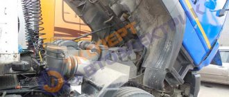
Connection diagram for PZD to KamAZ
1 — radiator of the car cooling system; 2 — coolant thermostat; 3 — car water pump; 4 — heat exchanger of the heating system; 5 - battery; 6 — heating system fan; 7 — fan switch; 8 — fuse block; 9 — heater; 10 — electric motor with pump; 11 - fuel line; 12 — electromagnetic fuel pump; 13 — fuel filter; 14 - timer - regulator; 15 - control unit for heater operation; 16 — relay for controlling the operation of the heating system fan; 18 — car fuel tank; 19 — fuel tank; 20 — fuel supply valve for the heater.