Connecting the engine power supply system.
To connect the diesel power system, it is necessary to remove the fuel sediment filter from the vehicle chassis, and instead install a coarse fuel filter 240-1105010 on the vehicle frame.
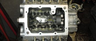
Install elbows 245-1104118-B1 -2 pcs. on the fuel pump (HPF) of the diesel engine. through copper sealing rings (Fig. 8)
, having previously removed the plastic protective sleeves from the fittings.
The fuel supply is carried out from the fuel tank to the coarse fuel filter, from the coarse fuel filter to the high pressure fuel pump. When laying fuel lines, make sure that the connections are tight and that the fuel line does not touch the moving parts of the vehicle.
Fuel is removed from the body of the high-pressure fuel pump into the vehicle tank for additional heating of the fuel in the tank in conditions of negative temperatures and removal of air entering the engine fuel system.
Device, spare parts and components.
SPARE PARTS FOR TRACTORS
ADJUSTMENTS OF MTZ TRACTORS ___________________
DIESEL ENGINE PARTS ___________________
MTZ SPARE PARTS CATALOG ___________________
TECHNICAL CHARACTERISTICS OF TRACTORS ___________________
SPECIAL EQUIPMENT BASED ON MTZ AND ATTACHMENTS ___________________
AGRICULTURAL MACHINERY AND EQUIPMENT ___________________
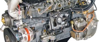
Fuel system of the D-245 engine
The fuel system (power system) D-245, in accordance with the configuration of diesel engines, consists of a fuel pump, injectors, low pressure pipes, high pressure fuel lines, intake manifold, exhaust manifold, turbocharger, coarse fuel filter, fine fuel filter, air cleaner , fuel tank, charge air cooler, muffler. The diagram of the fuel system D-245 (Fig. 1) MTZ-892, MTZ-92P indicates a means of facilitating diesel starting in conditions of low ambient temperatures - a glow plug.
Fig. 1 – Diagram of the power supply system (fuel system) D-245
1 — fuel tank; 2 – fuel coarse filter; 3- low pressure fuel pipes; 4 – high pressure fuel pump; 5 – fuel priming pump; 6 – high pressure fuel pipes; 7 — fine fuel filter (non-separable); 8 – air cleaner; 9 — fine fuel filter (with a replaceable filter element); 10 – glow plug; 11 – intake manifold; 12 – exhaust manifold; 13 – muffler; 14 – nozzle; 15 – fuel drain pipe into the tank; 16 — cylinder head; 17 – turbocharger; 18 – pneumatic corrector tube; 19 – charge air cooler.
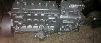
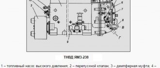
High pressure fuel pump TNVD D-245
On MTZ-892 and MTZ-92P engines, high-pressure fuel pumps TNVD-773 are installed. The high-pressure fuel pump (HPF) D-245 is a block design consisting of four pumping sections in one housing, having a cam drive of plungers and spool-type dosing of cyclic fuel supply.
To check the opening pressure of the injection valves, supply fuel to the injection pump head D-245 and, gradually increasing the pressure, observe at what pressure the fuel begins to flow out of the drain pipes. If this value does not fall within the limits of 0.04. 0.08 MPa, replace the discharge valve or its spring.
To adjust the angle at which fuel is supplied to the injection pump 773 MTZ-892, MTZ-92P, it is necessary to unscrew the discharge valve fitting, remove it from the seat and install a special device. Determine the lower position of the plunger, then rotate the cam shaft in accordance with the direction of rotation, set it to 5.45±0.05 mm. Record the angle corresponding to this position of the camshaft.
When the governor control lever rests on the maximum speed limit bolt, make preliminary adjustments to the start of turning off the fuel supply. The moment the fuel injection pump rack D-245 begins to move towards turning off the fuel supply must correspond to the table value. Otherwise, adjust the maximum speed limit bolt.
Check the amount of fuel supplied by fuel injection pump sections D-245 MTZ-892, MTZ-92P at nominal mode with an air pressure of 0.8+1 MPa in the cavity of the boost corrector membrane. The unevenness of feed across sections should not exceed the permissible 3%. If necessary, adjust by rotating the housings of the fuel pump sections 773 or by changing the number of shims under the corrector housing.
When the control lever is positioned against the maximum mode limiting bolt, check that the rotation speed corresponds to the complete shutdown of the fuel supply. This adjustment of the injection pump 773 (D-245) is made by changing the preliminary length of the regulator spring, then check that the fuel supply is turned off with the lever again.
When the stop lever is deviated by 40-45° from its original position, the fuel supply from all injectors at any camshaft speed and at any position of the regulator control lever must be completely turned off.
At a fuel supply speed corresponding to the maximum torque and air pressure Рк = 0.8-5-1 MPa, check the cyclic fuel supply for overloads. Adjust the stroke of the injection pump corrector rod D-245 using the castle nut of the corrector. The tightening force of the corrector spring is limited by the internal nut of the direct corrector. Adjust the anti-corrector by changing the preload of the reverse corrector spring using nut 12 and limiting its stroke with screw 13.
Fig.2. Appearance of the regulator TNVD-773 of the D-245 engine
1 — boost corrector; 2 - stop bolt; 3 — stop lever; 4 — bracket; 5 - bolt; 6 — bolt for adjusting the maximum rotation speed; 7 — control lever; 8 - minimum speed adjustment bolt, 9 - protective cap
Fig.3. Section of the regulator TNVD-773 of diesel D-245
1 — regulator body; 2 — regulator cover; 3 — inspection hatch cover; 4 — membrane body; 5 — membrane cover; 6 — load holder; 7 — regulator weight; 8 - coupling; 9 — reverse corrector pusher; 10 - slider; 11 — main regulator lever; 12 — reverse corrector lever; 13 — reverse corrector spring; 14 — reverse corrector screw; 15 — crank lever; 16 — crank; 17 — crank spring; 18 — earring; 20 — corrector body; 21- proofreader; 22 — direct corrector spring; 23 — direct corrector nut; 26 — main spring sleeve; 27 — main spring; 28 — main spring cup; 29 — axis of the control lever with a cam; 30 — double-arm lever; 31 — slatted leash; 32 — rack rod; 33 — starting spring; 34 - membrane; 35 — membrane plate; 36 — rod bushing; 37 — rod; 38 — lock washer; 39 — boost corrector spring; 40 — rod tip; 41 — return spring; 42 — feed switch lever; 58 - bolt; 62 - plug.
Adjust the cyclic feed at a camshaft rotation speed of 500 rpm1 and intermediate pressure values in the cavity of the boost corrector membrane by changing the preload of the corrector spring 39 or by rotating the lower spring housing. After completing the adjustment, tighten the locking screw. Adjust the cyclic supply for the fuel injection pump-773 in the absence of air pressure by rotating the rod 37 with the plug 62 unscrewed and the lock washer 38 bent.
Is it possible to add fuel to the fuel injection pump of a motorpal?
All the best. My question is, is it possible to add fuel to the injection pump of a motorpal, please tell me?
COMMENTS (28)
Denis Sokolov February 28, 2022 Andrey Tkachenko Denis Sokolov February 28, 2022 Ivan Galyadkin February 28, 2022 Evgeny Petrov February 28, 2022 Slavyan Ryazantsev February 28, 2022 Alexey Kabakov February 28, 2022 Evgeny Alexandrovich February 28, 2022 General Ivolgin Evgeny Alexandrovich February 28 2022 Alexey Myshkovets Evgeniy Alexandrovich February 28 2022 Evgeny Aleksandrovich Alexey Myshkovets February 28, 2022 Magomed Khizirov General Ivolgin March 03, 2020 General, I have a 245 without a turbine Igor Sysoev February 28, 2020 Maxim Lisok February 28, 2022 Dmitry Gorgun February 28, 2022 Igor Sysoev February 28, 2022 Igor Belykh February 28, 2022 Sergey Viktorovich 28 February 2022 Igor Borisenko Sergey Viktorovich February 29, 2022 Danil Nizamov February 28, 2022 Tagir Mamin February 28, 2020 Artem Lopushkov February 29, 2022 Tagir Mamin Artem Lopushkov February 29, 2022 Artem Lopushkov Tagir Mamin February 29, 2022 Igor Borisenko February 29 2022 Vadim Sorochinsky February 29, 2022 Vadim Sorochinsky February 29, 2022 Rostislav Zarubin March 01, 2022 Sergey Mikhailov March 01, 2020
Related Posts
T 25 fuel injection pump - MTZ. Why does the tractor stall after starting it cold, and so on until it warms up?
- Author: Oleg Vinokurov(admin)
- 18 April 19:30
Guys, what are the reasons? .T 25 fuel injection pump - MTZ. When you start it, it stalls, then you start it, drive and stall again, and so on until I think it warms up well. I don’t understand what the reason is. The fuel filter is new. Help, maybe someone has encountered this? Thanks in advance.
Tndv motorpal Engine d-260. Why doesn't it pull, doesn't start well, doesn't smoke under load. How to regulate this TDV?
- Author: Ruzal Gabdrakhmanov
- 11 April 10:40
Good day. Tndv motorpal of the D-260 engine, it doesn’t pull, it doesn’t start well, it doesn’t smoke under load, how to regulate this tndv? Have a great weekend.
How can you check the pressure of the injection pump on the MTZ80 without removing the pump from the tractor? Are there any special pressure gauges or devices?
- Author: Oleg Vinokurov(admin)
- 10 March 16:15
Good afternoon. Tell me, how can I check the pressure of the injection pump on the MTZ80 without removing the pump from the tractor? Are there any special pressure gauges or devices?
I installed a new engine on the D240, set the fuel injection pump and injectors to 180. Why did the tractor stop picking up speed and is running with white smoke (it doesn’t fit into the chimney)
- Author: Vladislav Parshin
- November 07, 2020
Guys, here’s a question: I installed a new fuel injection pump on the D240 engine and set the injectors to 180, the tractor stopped picking up speed and runs with white smoke (it doesn’t fit into the pipe)
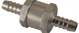
Where is the check valve located on the fuel injection pump? JCB 3CX tractor.
- Author: Oleg Vinokurov(admin)
- April 14, 2020
Hi all. Help out. Where is the check valve located on the injection pump? JCB 3CX tractor. Thank you.
What is the electrical circuit of the YuMZ-6 tractor?
- Author: Mikhail Yambarshev
- 05 November 09:30
- 2 comments
Good day. Can anyone post the electrical diagram of the YuMZ-6 tractor?
How to restore documents for a tractor?
- Author: Alexey Chernov
- 04 November 23:18
Hi all! Can you tell me who restored the docks on the tractor?
Tractor VTG-100, Why does the voltmeter show little? Tell me the possible reasons, the engine is from MTZ - 1221, when the heater or headlights are on, it gets worse.
- Author: Ruzal Gabdrakhmanov
- 02 November 23:38
Fuel injection pump of diesel engine D-245 - design and adjustments
On the D-245 engine of the ZIL-5301 Bychok, GAZ-3309, MAZ-4370 Zubrenok cars, fuel injection pumps-773 are installed. The high-pressure fuel pump is a block design consisting of four pump sections in one housing, having a cam drive of plungers and spool-type dosing of cyclic fuel supply.
TNVD-773 is designed to supply metered portions of fuel under high pressure into the combustion chambers of diesel cylinders at certain points in time. The fuel pump camshaft is driven from the diesel crankshaft through distribution gears.
The relative position of the fuel pump drive gear and the drive coupling half is fixed by tightening the nuts installed on the coupling half studs. The tightening torque of the nuts is 35…50 Nm.
The D-245 high-pressure fuel pump is combined into one unit with an all-mode regulator and a piston-type fuel priming pump.
The regulator has a fuel supply corrector, an automatic fuel enricher (at starting speeds) and a pneumatic smoke limiter (boost corrector). The booster pump is installed on the fuel injection pump housing D-245 and is driven by the cam shaft eccentric.
The working parts of the pump are lubricated with flowing oil coming from the diesel lubrication system. The oil is drained from the pump housing into the diesel crankcase. The newly installed pump on a diesel engine must be filled with oil in the amount of 200…250 cm3. Fill oil through the oil drain hole pos. 30 (Fig. 1).
Fig. 1 – Fuel pump TNVD 773 diesel D-245
1 - fuel pump section; 2 — plate; 3 – flange; 4 – key; 5 – drive coupling half; 6 – nut for fastening the coupling half; 7 – cam shaft; 8 – fuel pump housing; 9 – fuel priming pump; 10 – supporting bracket; 11 – starting feed adjustment bolt; 12 – stop lever; 13 – regulator body; 14 – regulator cover; 15 – inspection hatch cover; 16 – minimum rotation speed adjustment bolt; 17 – bolt for adjusting the maximum rotation speed; 18 – nut securing the fuel pump sections; 19 – bypass valve; 20 – fuel supply fitting; 21– oil line; 22 – fuel outlet fitting from the booster pump to the fine fuel filter; 23 – bolt securing the fuel supply fitting to the booster pump; 24 – boost corrector; 25 – bolt of the air supply fitting; 26 – control lever; 27 – screw plug for adjusting the nominal fuel supply; 28 – air bleed plug; 29 – stop electromagnet; 30 – oil drain hole.
Motorpal fuel injection pump repair
All modern trucks are equipped with powerful diesel engines, the advantages of which, first of all, fuel efficiency and high torque throughout the entire speed range, cannot be realized if the fuel system of the vehicles is in poor condition.
It is sometimes believed that repairing truck fuel injection pumps is much simpler than repairing similar systems in passenger cars, but this is completely wrong. The fact is that these systems not only have different performance, but also seriously differ in design, so comparing the repair of a Delphi injection pump, the repair of a Denso or Bosh injection pump with a KamAZ or KrAZ pump that performs the same functions hardly makes practical sense.
Motorpal is a leader in its class
This Czech company is known throughout the world as a manufacturer of high-quality fuel supply systems for all types of diesel engines of trucks, tractors and heavy construction equipment, and original technical solutions, some of which have been used since the late 40s of the last century, guarantee reliable operation of all systems The company's achievements are no less appreciated by those who repair engines - the diesel powered by equipment under this brand is easy to maintain and will never present any unpleasant surprises.
The main part of the products are single-cylinder pumps without their own drive, as well as multi-cylinder systems with a camshaft drive, valves, injectors and sprayers for them, as well as fuel filters and much more. In the manufacture of fuel equipment, high-quality materials and innovative technologies are used, some of which are unique.
You can find out the cost of work and sign up for service by phone
Common problems and their prevention.
The most common problem with fuel injection pumps is uneven and reduced fuel supply. This causes wear of a large group of mechanism elements, such as plunger pairs, valves, racks and bushing rims. For this reason, the throughput of the injectors is also reduced. The consequence of all this is a loss of power and increased fuel consumption.
The mechanism wears out even when the timing of fuel injection is delayed. If a breakdown of the cam shaft, its bearings and keys occurs, this leads to absolute failure of the fuel injection pump or, at a minimum, leads to noticeable deviations. Therefore, it is important to ensure that the camshaft nut is sufficiently tightened to avoid such problems, as well as, in general, to ensure the tightness of all components.
Maintenance of the high pressure fuel pump TNVD diesel engines D-245
During operation of the high-pressure fuel pump 773, when the main parts wear out, its adjustment parameters are violated. Injection pump lubricant D-245 is centralized from the diesel lubrication system through a special oil line. The required oil level in the pump crankcase is set automatically.
To reduce wear of precision parts, it is not allowed to operate the injection pump without a filter element or with a clogged fine fuel filter. It is also not allowed to work with fuels that have a high water content.
If necessary, and also every 120 thousand km, it is necessary to remove the pump and check it on a stand for compliance with the adjustment parameters, as well as the setting angle of advance of fuel injection on a diesel engine. If necessary, make appropriate adjustments.
Installation of injection pump, injectors, high and low pressure pipes D-245
The injection pump mating plate must be clean; nicks and other damage to the slab are not allowed.
The fuel pump gasket must not show any visible damage.
When installing the fuel pump, you must align the marks of the fuel pump drive gear and the splined flange.
The splined flange of the fuel pump gear must fit freely, without jamming, onto the splines of the fuel pump shaft bushing.
The fuel pump gear flange mounting bolts must be tightened to a torque of 18…25 Nm.
When installing the fuel pump, be sure to check the fuel injection advance angle.
This is done in the following sequence:
- set the regulator control lever to the position corresponding to the maximum fuel supply.
- Disconnect the high-pressure tube from the fitting of the first section and connect the momentoscope instead (Fig. 1).
- Turn the diesel crankshaft clockwise with a wrench until fuel free of air bubbles appears from the glass tube of the momentoscope.
- remove some of the fuel from the glass tube by shaking it.
- Turn the crankshaft counterclockwise 30...40°.
- Slowly rotating the diesel crankshaft clockwise, monitor the fuel level in the tube; at the moment the fuel begins to rise, stop rotating the crankshaft.
- If the latch does not coincide with the hole in the flywheel (Fig. 2), make adjustments by doing the following:
- remove the hatch cover;
- Unscrew bolts 1, 2 and 3 (Fig. 3) and loosen bolt 3 by ½…1 turn (do not unscrew the bolt);
- align the locking rod 2 (see Fig. 2) with the hole in the flywheel, turning the diesel crankshaft in one direction or the other; Using a wrench, turn the fuel pump shaft and splined flange by the nut until the fuel begins to rise in glass tube 1 (see Fig. 1) of the momentoscope;
- install bolts 1,2 and 3 (see Fig. 3) into matching holes, trying to position them as evenly as possible around the circumference;
5. tighten bolt 3 first, then bolts 1 and 2;
- Reinstall the high-pressure tube and remove the locking rod from the hole in the flywheel;
- Replace the hatch cover.
The alignment of the splines of the fuel pump bushing and the splined flange when installed on a diesel engine is ensured by turning the diesel crankshaft or the pump camshaft.
Diesel engines must be equipped with injectors of the same group.
The sealing gaskets on the side adjacent to the injectors must be lubricated with solid oil US-1 GOST 33-51.
The injector mounting bolts must be tightened to a torque of 20…25 Nm.
High pressure pipes must be secured at a distance of 10...15 mm from the union nuts with clamps with gaskets.
Low pressure fuel pipes should be purged with compressed air before installation on a diesel engine.
Technical characteristics of fuel injection pump for MTZ 80 82
| Indicators | UTN 5 | 4 UTN | 4 UTNM |
| Plunger diameter mm | 8,5 | 9 | 9 |
| Plunger stroke mm | 8 | 10 | 8 |
| Nominal rotation speed of the injection pump shaft rpm | 1100 | 1100 | 1100 |
| Rotation speed corresponding to diesel idle rpm | 1170 | 1160 | 1160 |
| Regulator start speed rpm | 1115 | 1115-1125 | 1115-1125 |
| Maximum torque speed rpm | 850 | 850 | 850 |
| Correction stop speed rpm | 1040-1100 | 1040-1100 | 1030-1090 |
| Cyclic fuel supply at 40-50 rpm. camshaft mmᶾ/cycle | 120 | 140 | 140 |
| Rotation speed of automatic shutdown of fuel supply to injectors rpm | 950 | 1210 | 1250 |
| Unevenness of fuel supply by sections % min. speed/maximum speed | 6/30 | 6/30 | 6/30 |
| Angle of start of fuel supply by the section along the meniscus to TDC (along the cam profile) | 57 | 57 | 57 |
Checking diesel injectors D-245 for injection start pressure and fuel atomization quality
Fig. 4 – D-245 engine injector
1 – nozzle body; 2 – adjusting washer; 3 – spring; 4 – nozzle rod; 5 – spacer; 5 – sprayer nut; 7 – sprayer; 8 – sealing ring.
Check the injectors every 120 thousand km. Remove the injectors from the diesel engine and check them on a stand. The injector of the fuel pump TNVD 773 is considered to be in working order if it sprays fuel in the form of a mist from all five holes of the nozzle, without separately flying drops, continuous streams or thickenings.
The beginning and end of the injection must be clear; the appearance of drops on the toe of the nozzle is not allowed. Check the spray quality at a frequency of 60-80 injections per minute.
If necessary, adjust the nozzles by changing the total thickness of the adjusting washers 2 (Fig. 4): increasing the total thickness of the adjusting washers (increasing spring compression) increases the pressure, decreasing it decreases it. A change in the thickness of the washers by 0.1 mm leads to a change in the pressure at which the nozzle needle begins to rise by 1.3... 1.5 MPa.
Injection start pressure values for injectors: 455.1112010-50 – 24.5 MPa; 172.1112010-11.01 – 25.0…26.2 MPa. Install the injectors on diesel. Tighten the injector mounting bracket bolts evenly in 2-3 steps. The final tightening torque is 20…25 Nm.
Injector test.
In addition to checking the high-pressure fuel pump, an integral stage of servicing the D-245 engine is testing the injectors. The start and end points of injection must always remain clear. If the nozzle tip has remaining droplets, a deviation has occurred. This factor is checked during cyclic injection with an amplitude of 60-80 injections/min.
Adjusting the nozzles is quite simple by equalizing the thickness of the adjusting washer. The more the spring is compressed, the more the pressure increases, and vice versa. To deflect the pressure by 1.5 MPa to one side, a decrease or increase in the thickness of the washer by 0.1 mm is required.
Types of fuel pumps
There are three main types of fuel pumps:
- In-line.
- Distribution.
- Trunk.
In in-line installations, fuel is supplied to each cylinder by a separate plunger-bushing pair.
In distribution devices, the mixture is supplied by one or two pairs of devices.
In mainline installations, fuel is pumped into the fuel rail. A similar design is used in the Common Rail system.
Depending on the mixture flow rate, low and high pressure pumps are distinguished.
D-245 engines use devices like TNVD-773. MAZ, GAZ, ZIL and other domestic cars are equipped with such power plants.
TNVD-773
Cost of injection pump and components.
A new fuel pump will cost the buyer 25-50 thousand rubles, depending on the manufacturer. Let's take, for example, the MOTORPAL company - fuel injection pumps produced by it have a price of 25-35 thousand rubles.
It is also worth mentioning the approximate cost of the main spare parts that may require replacement, which are adequate for the current market: - nozzles (1500-3000 rubles / piece); — installation plate (3000-5000 r); — fuel injection pump drive gear (3000-5000 r); — fuel injection pump gear shaft for D-245 (3000-5000 r); — high pressure fuel line (up to 1000 r); — fuel pump (1500-3000 r).