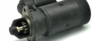
Tractor brakes T-25
The Vladimirets 25th model uses double floating-type band brakes, which operate independently and are located in the intermediate sleeves between the housing final drives.
The brakes consist of a steel band and a strong cast iron pulley, which is equipped with a friction lining, which increases resistance and increases friction.
A brake hose is attached to the side surface of the main body of the T-25 tractor gearbox using two pins and several studs. The final drive housing is attached to the smaller flange.
The material from which the brake pulley is made (position 13, see the diagram below) is cast iron, and it is mounted on the shaft of the final drive drive gear and secured with two keys.
Any movement along the pulley axis is limited by retaining rings located in the grooves.
Its outer surface is covered with steel tape. Its ends are eyelets with steel rivets. The inner surface of the tape is equipped with an asbestos-based lining; it is secured using tubular rivets on a brass base.
T-25 tractor brake diagram
To begin with, we present the very diagram of the brake system of the T-25 tractor, and below we present its description.
As we said earlier, the brakes are band and floating. Both of them are located in a cast iron sleeve (15) and connect the final drives to the main drive housing.
At the same time, each brake is equipped with its own control pedal.
The brake band covers the pulley 270° and tightens when you press the brake pedal (1). Using a lever (item 6), a hinge (8) and a rod (9).
After the end of the effort on the pedal and braking, it returns to its original place with the help of return springs. In order to perform braking with both wheels when performing work on stationary machines, the pedals must be blocked using the bar (17). If you are forced to stop on an inclined surface, you need to fix and tighten the brakes using the latch (2).
content .. 81 82 86 ..BRAKES AND BRAKE SLEEVES FOR TRACTOR T-25
The T-25 tractor is equipped with two floating band brakes, acting independently of one another on the shafts of the drive gears of the final drives and the drive wheels associated with them.
Brake hose 2 (Fig. 62) is attached with studs and two pins to the side surface of the main gear housing. The final drive housing is attached to the smaller flange of the sleeve. The cast iron brake pulley 26 is mounted on the shaft of the final drive drive gear on two keys 25. The pulley is held against axial movements by spring retaining rings 1 located in the grooves of the keys.
The tape 28 covers the outer surface of the brake pulley. The tape is made of special steel, its ends are made in the form of eyes and riveted with steel rivets. An asbestos lining is riveted to the inner surface of the tape with tubular brass rivets. Pins 3 are inserted into the eyes of the ends of the tape, connecting it to the brake levers 4 and earrings 15. The second ends of the earrings are connected to rod 5 using pin 14.
The brake levers 4 are secured with screws with tapered shanks on the axles 7, freely installed in the horizontal bores of the cover 8. The axial movements of the axle 7 and the pedal rollers 12 and 24 are kept from the axial movements by the pins 9 inserted into the drillings of the cover and the annular grooves of the axles and rollers. The top of the sleeve cover is closed with a lid 10.
A torsion spring 16 is installed on each axis 7. The coils of the spring are placed on both sides of the head of the brake lever, the upper bent end of the spring rests against the cover 10, and the lower ones press on the eyes of the brake band and move the band with the brake levers away from the pulley. The brake levers 4, under the action of springs 16, are pressed against the spherical shanks of the adjusting thrust bolts 6, screwed front and back into the sleeve cover and secured with locknuts. At the bottom, the tape rests on the adjusting screw 27.
The shafts 12 and 24 of the left and right brake pedals pass through the middle bores of the covers 8. On the right, the right brake pedal 22 is welded to the short shaft 24. The long shaft 12 of the left brake pedal passes over the main gear housing. The left brake pedal 23 is attached to the right end of the shaft with a bolt with a conical shank. A thin-walled brass bushing is inserted into the pedal hub, through which the left brake pedal shaft 12 rests on the end of the right brake shaft protruding from the cover 8. Tension springs 21 press the pedals against the stop 17, welded to the floor.
On each pedal shaft, a lever 13 is secured with a bolt with a conical shank, into the conical drilling of which there is a spherical nut screwed onto the threaded end of the rod 5. When the pedal is pressed, the rod rotates along with the shaft and turns the lever 13, which moves up the spherical nut 11 and connected to it pull 5 with earrings. In this case, the earrings move the lower heads of both levers 4 to the middle of the brake sleeve. The ends of the belts are brought closer together and the belt is pressed against the brake pulley.
The diagram of how the brake works when the tractor is moving forward or in reverse is shown in Fig. 63.
When the tractor is operating in forward motion, the pulley rotates in a clockwise direction (Fig. 63.6). After the band touches the brake pulley, the rear brake lever 6 with the advancing end of the band will be thrown back by friction forces until it stops against the adjusting bolt 7. The brake will be tightened by moving the trailing end of the brake band using the front brake lever 9. Frictional forces between the lining and the pulley will drag the belt in the direction of tightening, which ensures reliable braking with little effort on the pedal.
When the tractor is operating in reverse, the pulley rotates in the opposite direction (Fig. 63, c). In this case, the forward end of the brake band and the front lever 9 will be oncoming
pressed against the stop 8, and the brake will be tightened by moving the running end of the brake band using the rear brake lever 6.
After braking is completed, the release springs 21 (see Fig. 62) return the brake pedals to their original position, and the springs 16 remove the band from the brake pulley. The pedals should return to their original position freely, without jamming. If the pedal jams and it does not return all the way to the floor, then it is necessary to loosen the bolts securing the covers 8 and rotate the covers within the gap between the holes in them and the bolts, ensuring the alignment of the bores under the axes of the right and left brake pedals.
The brake pedals are located at the right fender of the tractor. A locking bar 20 is riveted to the right pedal pad, which can be inserted into the slot of the left pedal, in which case the pedals will be rigidly connected to each other and when one pedal is pressed, both brakes will operate.
When stopping the tractor on a slope and working with stationary machines, the interlocked brakes are secured with a latch 18. The latch is installed on a bracket 30 attached to the main pedal housing together with the right cover of the shift rollers. Spring 31 presses the latch against the door. To fix the tightened brakes, it is necessary to move the latch forward so that one of the latch teeth engages with pin 19 welded to the left brake pedal. In order to release the fixed pedals, it is necessary to press the pedal, in which case pin 19 will disengage with the latch tooth and spring 31 will throw the latch back until it stops in the floor.
In an unbraked state, the gap between the pulley and the lining is 1-1.5 mm, which corresponds to a pedal stroke of 30-50 mm. Adjust the gap with screw 27 and thrust bolts 6. In correctly adjusted brakes, the travel of the right and left pedals should be the same, since uneven tightening
brakes when operating at transport speeds, especially on slippery roads, can cause the tractor to turn sharply and lead to an accident.
Oiling of the brake band linings reduces the efficiency of the brakes, so the ends of the drive shaft coming out of the main and final drives are sealed with self-clamping oil seals. To drain oil that has leaked into the brake sleeve, there is a hole with a cotter pin 29 in the lower part of the sleeve.
Rice. 62. Sleeves with brakes: 1 — retaining ring; 2 — brake sleeve; 3 — tape finger; 4 — brake lever; 5 — adjusting rod; 6 — adjusting thrust bolt; 7 — brake lever axis; 8 — brake cover; 9 - pin; 10 — top cover; 11 - spherical nut; 12 — shaft of the left brake pedal; 13—lever; 14 - finger; 15 — earring; 16 - spring; 17 — pedal stop; 18 — mountain brake latch; 19 - finger; 20 — brake blocking bar; 21 — tension spring; 22 — right brake pedal; 23 — left brake pedal; 24 — shaft of the right brake pedal; 25 - key; 2c - brake pulley; 27 — adjusting screw; 28 — brake band; 29 — cotter pin; 30 — mountain brake latch bracket; 31 - latch spring.
Rice. 63. Brake operation diagram:
a — the brake is released; b — the brake is applied when the tractor moves forward (the arrow shows the direction of rotation of the brake pulley); c — the brake is applied when the tractor moves backward; 1 — brake pulley; 2 — brake band; 3 — brake pedal; 4 — lever; 5 - traction; c — rear brake lever; 7 — rear adjusting thrust bolt; 8 — front adjusting thrust bolt; 9 — front brake lever; 10 - earrings.
content .. 81 82 86 ..
How the brakes work
At the moment of forward movement of the T-25 tractor, the pulley rotates clockwise. At the moment of braking, the tape begins to touch it, and the rear brake lever is thrown back by friction until it rests against the adjusting bolt.
The brakes are tightened by moving the end of the band and the front lever. In this case, a friction force arises (between the lining and the pulley) which moves the belt towards the puffs, with minimal force on the brake pedal.
In reverse: the pulley rotates counterclockwise. Then the lever is pressed against the stop and the front end of the belt becomes the forward end and braking occurs using the rear brake lever.
At the end of braking, the springs return the band and pedal to their original position.
Important! In this case, the pedal should return to its original position without jamming.
If this happens, then you need to loosen the fastening bolts and turn the covers within the permissible gap.
If oil gets on the brake band linings, the effectiveness of the brakes is greatly reduced; for this, the ends of the shaft are sealed with self-moving oil seals.
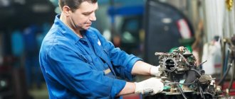
When is it necessary to adjust MTZ injectors?
Engine injectors are checked at TO-3, i.e. every 960 operating hours. In this case, the injectors are removed from the engine and placed on a special stand. A stand for adjusting MTZ injectors allows you to determine the operating pressure and, if necessary, adjust it, since during operation the pressure often decreases. In addition to pressure, characteristics such as:
- uniformity of fuel atomization;
- absence of individual drops or jets;
- clear start and end of injection;
- no drops on the spray nozzle.
If there is a deviation in at least one indicator, it will be necessary to install a new nozzle on the MTZ or adjust the existing one if it has not yet exhausted its service life.
Unscheduled adjustment of injectors MTZ 80, 82 and other models is necessary if problems are observed in engine operation. Usually noted:
- power drop;
- sharp operation of the engine, jerking;
- uncontrolled speed of the power plant;
- cold start problems;
- problems starting the engine after a short shutdown;
- the appearance of knocking (and vibrations) in the area of the fuel line;
- smoky release.
These problems are not specific and may indicate damage in various power plant systems. However, the reason may also be poor adjustment of the injectors on the MTZ. In any case, it is worth removing and checking the injectors on a stand before overhauling the injection pump or engine.
How to properly adjust the brakes on the T-25
During operation, there is a natural decrease in the surface of the pulley and the belt lining, which entails an increase in the gap. This leads to a deterioration of the tractor's braking system and an increase in free movement.
Remember! The standard gap is 1.5-2 mm, and the pedal travel is 40-50 mm.
If you have deviations from these values, you need to make adjustments. Also, adjustment must be carried out if the travel of the pedal pads is more than 70 mm.
The process of adjusting the T-25 brakes is done using adjusting and pressure screws, for this you need:
• Loosen the lock nut of the screw (pos. 16) and the pressure bolts (3) a couple of turns; • Screw them in until they stop, and the difference in measurements A should not be more than 1 mm, then release them 1-2 turns; • We fix the screws and bolts with locknuts; • Screw in the hinge (8) until it comes into contact with the conical surface of the lever (6) and tighten it with a nut (7).
Remember! a failed adjustment will ensure reliable operation of the brakes and joint braking of the drive wheels.
The adjustment process does not take much time and effort, and this procedure significantly extends the service life.
MTZ 82
The Belarusian-made tractor is equipped with dry disc brakes mounted on the final drive gear shafts and protected by casings. A pair of working bodies are located in cylindrical housings on both sides of the transmission housing. When the drive is activated, the brake mechanism works to stop the drive shafts.
Adjusting the brakes of the MTZ 82 tractor is considered mandatory during daily inspection of the equipment. The test is carried out on a dry, hard surface. The car is accelerated to 25 km/h and stopped abruptly, while the braking distance should not exceed 9 m. The difference between the tracks on the right and left sides cannot be more than 1 m. The discrepancy in parameters requires adjustment.
Uniform braking is ensured by adjusting the travel of the drive pedals. For the MTZ 82 model, this parameter is 70-90 mm. If it is less, then rapid wear of the linings and overheating of the brakes is possible. A jammed pedal also indicates a malfunction. The optimal parameter can be achieved by changing the length of adjusting screw 2. Technically, the process goes like this:
- Unscrew the lock nut of the bolts and turn the bolts into the adjusting forks so that the pedal travel reaches normal.
- Tighten the locknuts and check the pedal stroke again.
If the screw thread is not long enough, this indicates critical wear of the brake discs or contact surfaces.
If the brakes operate asynchronously after tightening the screw, then disassemble the system and replace the part that has failed. For analysis, follow the diagram.
1 – disc, 2 – fastening shaft, 3 – brake pedal, 4 – brake lever, 5 – casing, 6 – pressure discs.
The MTZ 82 tractor, in addition to the working brake system, is equipped with a manual parking brake, which ensures a complete stop of the machine on a slope of 18%. To ensure proper operation, the following steps are carried out when inspecting the machine and diagnosing problems:
- move the lever forward and release the brake;
- unscrew the locknut of the adjusting screw 1 and 7;
- combine lever 4 with fork 6 and B1 with B2;
- insert finger groove 5;
- begin to tighten screw 1 until the brake force when measuring 400N is at the level of 3 and 4 clamps;
- tighten the nut until it stops.
To avoid failure of the brake system of the MTZ 82 tractor, in addition to daily inspection and tightening of screws, you must follow the operating rules for this unit of the machine:
- avoid constant clamping of the pedal, which leads to wear and tear of the system;
- do not use sharp braking, which is considered to cause abrasion of the brake limiters;
- Inspect the system daily to diagnose physical damage.
Causes of breakdowns of brakes, final drives and their elimination on T-16, T-25
It is necessary to remove the sleeve and the final drive mainly for two reasons: failure of the brakes and destruction of the tapered bearings in the final drive gear reducer. The T-16 is equipped with band brakes; they are located in the sleeves connecting the main housing with the final drive. Each side of the brakes is controlled by a separate pedal, which allows the chassis to brake each wheel separately during sharp turns.
Brake maintenance is carried out by regularly inspecting the rods and connections, adjusting the gap between the pulley and the belts. The effectiveness of the brakes decreases when the working surfaces of the belts and drums are oiled; the reason for oil getting into the brake cavities may be the lack of tightness of the frame seals. After removing the side housing and replacing the seals, the brake mechanism must be thoroughly washed with kerosene. After assembly, be sure to check the synchronization of the braking of the drive wheels.
Do not brake a tractor moving in high gears without first disengaging the clutch; if this is not done, then damage to the brake mechanism cannot be avoided. Periodically inspect the quality of the cotter pins, the tightening of the locknuts and the fastening of the return springs. A single-stage gear reducer (onboard) is attached to the outer flange of the hose. It must also be systematically inspected for oil leaks and the axial clearance in the tapered bearings must be checked and adjusted.
If oil leaks are detected on the side of the wheel axle flange, you need to check the oil seal or diaphragm seal. To check the axial clearance of the bearings, you need to remove the wheel. If there is noticeable movement of the axle flange, the gap should be adjusted using paired halves of shims placed under the bearing cup so that the gap in the bearings decreases. After adjustment, the wheel axle should rotate freely without jamming or wobbling of the axle flange.
After replacing the bearings and adjusting them, you should rinse the entire gearbox with onboard kerosene, then fill it with fresh oil up to the inspection hole. After installing the side with the sleeve in the seat to the main gear housing, it is advisable to install new lock washers on the flange studs and for some time after the first trips make sure that the stud nuts do not loosen.
If you follow these simple rules, you will not have to once again remove the side with the hose to repair the brakes or replace bearings with seals.
Source
Characteristics of injectors MTZ 80, 82 and other Belarusians
The MTZ 80 and MTZ 82 tractors are equipped with D-240/D-243 diesel engines, depending on the year of manufacture and modification; D-242, D-245 and D-260 engines are also found. The principle of operation of fuel injectors on these engines is the same, but the design may vary slightly. For D-240 and D-243 engines, nozzles of the FD 22 or FDM type are suitable. You can find them by catalog numbers 171.1112010-50, 171.1112010-01, 171.1112010-02.
The main difficulties in adjusting MTZ injectors are that even with the same markings of parts, their characteristics may differ. In order to carry out quality repairs and optimally adjust the nozzles, it is necessary to clarify the diameter of the nozzle and read the information in the technical documentation.
The main parameters that you need to know to adjust the MTZ 80, 82 injectors are as follows.
Injection pressure
This is one of the most important characteristics, and it is on this basis that MTZ injectors are adjusted. Injection pressure, or nozzle lift pressure, affects the duration, intensity and quality of fuel atomization:
- when the pressure decreases, the duration of diesel injection increases, drops or jets may appear, and the quality of atomization decreases;
- as the pressure increases, the needle may stick in the lower position, the injection time is reduced, which means the volume of the supplied portion of fuel decreases, which in turn leads to a drop in power.
What pressure should I set when adjusting MTZ injectors?
When performing repairs and adjustments of fuel injection pumps and MTZ injectors, you must be guided by the information provided in the technical documentation. The same engine can operate with injectors designed for different injection pressures, so it is selected based on the specific modification of the nozzle and the diameter of the needle hole.
Old-style injectors are designed for a pressure of 170-185 kg/cm2.
The new type of injectors are designed for a pressure of 220-228 kg/cm2.
On the stand for adjusting MTZ injectors, a value is set 5-10 kg/cm2 higher - this is a compensation gap necessary due to the pressure drop when parts are heated and their expansion.
If you do not check the technical data, you can disrupt the stable operation of the engine. For example, during the repair process, a master can set an old-style nozzle to 180 kg/cm2, while the remaining three will work at the factory settings, i.e. at a pressure of 220 kg/cm2. As a result, the engine's working life is reduced, and the operation of the tractor itself will be associated with a number of problems.
How to adjust the pressure of MTZ injectors?
To diagnose or adjust MTZ injectors, they are removed from the engine and installed on a special rack. The stand for adjusting MTZ injectors can have different configurations. The most common options are KI-562, KI-3333, KI-15706, etc.
You can also adjust the MTZ 80, 82 injectors with your own hands without a stand and without dismantling at all. For this, a special device KI-16301A and an autostethoscope are used. The device is connected to the injector under test, first disconnecting it from the fuel line. After this, the handle creates a forced fuel supply.
Having set the required pressure values, you need to check the quality of fuel atomization. An autostethoscope is used for this - through it you can hear a characteristic click. This sound means that the spray needle has clearly seated itself in the nozzle seat. Spray quality is checked at 60-80 injections per minute.
Spray diameter
The cross-section of the nozzle needle directly affects the injection pressure, so these characteristics are interrelated. When adjusting MTZ nozzles, it is important to set the pressure that is recommended for a specific atomizer. They are available in the following sizes:
- 6 mm – needle section size 5x0.35, injection pressure 185 kg/cm2;
- 5 mm – needle cross-section size 5x0.32, injection pressure 228 kg/cm2;
- 5 mm – needle cross-section size 5x0.34, injection pressure 220 kg/cm2.
Thus, the process of installing injectors on MTZ is as follows:
- You decide what fuel injection pressure you would like to achieve.
- Buy nozzles with a suitable spray needle section.
- Adjust the MTZ injectors to the pressure recommended by the manufacturer.
In this case, for repairs you will need to remove and disassemble the nozzle, wash it, and remove traces of carbon deposits. To punch a hole in the nozzle, you can use a needle or a metal string with a diameter of no more than 0.28 mm. If after this it is impossible to set the operating parameters, you will need to install a new atomizer (complete with needle) or nozzle on the MTZ.
modernization of drum / band brakes T-25
Questions can only be asked after registration. Please login or register.
In general, I'm creating a topic. the rules are as follows: 1. everyone who writes about their own brakes - they are good, very wonderful - the messages will rub off. 2. adjustment and maintenance of original brakes - there is a separate topic for this, everything will be covered here in the same way. here is a link to that topic: https://fermer.ru/forum/t-25t-30-kluby-lyubiteley-i-vladelcev-traktorov-.
So. Due to the fact that our terrain is very rough, I was not immediately satisfied with the brakes, although they were rebuilt, 1 new drum and both bands were installed. Perhaps it’s a matter of the quality of the bands and friction material, but watching the forum it became clear to me that even when using native brakes, only “plain inhabitants” speak more or less well of them. If you use them constantly or use them on slopes, the tapes will not last long. If the tractor stops on a straight line, then with units on slopes the original brakes are extremely ineffective.
At first I was thinking of installing brake discs and calipers from the Oka instead of the drums. members of the forum from the “homemade mini tractors” thread took measurements for me, and it turned out that neither the disc nor the caliper could be placed in the sleeve body.
Source
Related Posts
Why, after repairing the injection pump and injectors, did it begin to bark and drive the diesel fuel into the sump? MTZ 82? What could be the reason?
After repairing the injection pump and injectors, it began to bark and drive diesel fuel into the sump. MTZ 82. What could be the reason?
Why do they make a return line from the injection pump, previously they did it from the injectors?
Greetings to all. Previously, the return was from the injectors, but now why did they go to make a return from the injection pump?
Why does the MTZ 82.1 stop starting from the manifold, everything is in the interior? Tvnd repaired in place with injectors. Perhaps there is something wrong with the marks on the gears?
Guys great! Guys, please tell me who had any problems with MTZ 82.1? I have such a problem, it stopped starting at all from the manifold, everything is stuck. In general, we can’t get it into any kind, the TVD has been repaired in the place with the injectors. We decided to look, maybe there’s something wrong with the marks on the gears?
MTZ 82.1. Why does the oil pressure press from under the nozzle? A month ago I took everything for repairs, both the injectors and the injection pump.
Gentlemen colleagues. Good evening everyone. Give me some advice. There is diesel pressure coming from under the nozzle. A month ago I waxed everything for repairs, including injectors and fuel injection pumps. What could it be and how to treat it?
MTZ 82.1 Thanks for the answers.
What pressure should be in the MTZ 1221.2 injectors?
What pressure should be in the MTZ 1221.2 injectors?
Why, after replacing the fuel pump on the MTZ 82, did the fourth cylinder stop working, although fuel is supplied (the injector sprays)?
Hello everyone. Guys, the question is why, after replacing the fuel pump on the MTZ 82, the fourth cylinder stopped working, although the fuel is supplied (the injector sprays)? Thank you in advance.
Water is oozing from under the nozzles on the MTZ-80. What could be wrong?
Hello everyone, this is a problem: water is oozing from under the injectors on the MTZ-80, what could it be?
Is it possible to check the pulse on the injectors in the field using a tester or control?
Is it possible to check the pulse on the injectors in the field using a tester or control?
Tell me what to do?
Guys, great. I come to you for advice. At MTZ 80 I was tired of repairing injectors. A week or two and again the smoke does not come into the chimney when it sits at idle, and the solarium goes into the pan. I am changing the filter, the head is new, the piston head is also new, the pump is also overhauled. I've already broken my whole head. Maybe someone has encountered this, please tell me.
What to do if water knocks out of the MTZ 82 radiator? Has the gasket blown or what?
Guys, what should you do if water knocks out of the MTZ 82 radiator? Has the gasket blown or what? Thanks for answers.
Source