- home
- Media center
- Articles
- How to bleed the clutch on a KAMAZ
Menu
- News
- Articles
- Video materials
- Photo materials
- Publication in the media
- 3D tour
12.08.2019
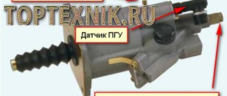
The pneumatic hydraulic booster on KamAZ helps the driver use less force to press the clutch pedal. If the clutch system begins to work incorrectly, you can try to bleed the PSU. The PSU needs to be periodically pumped, because the clutch is a highly loaded unit, so sometimes extraneous noise, crackling, and slippage occur.
The PSU is integrated into some old and almost all new Kamaz models. The primary task of this unit is to ease the driver’s labor costs, because the clutch in a KamAZ, as practice shows, is very massive, the springs press the discs very strongly, so frequently turning the accelerator on and off can be a very tedious task.
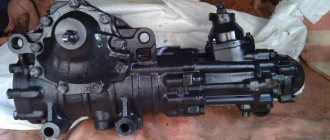
On some Kamaz models, the PGU is part of a divider installed between the clutch and gearbox. When changing gears, the driver turns off the divider, after which the pneumatics turn on. The divider is switched off using the PSU rod drive valve. That is why the divider turns on and off along with pressing or releasing the clutch pedal. This gearbox operating system is organized in many Kamaz models, and it is especially popular for modern modifications of trucks. Classic examples of such a switching system design can be considered KamAZ 5320, 65115.
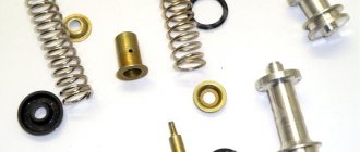
Technically, the PGU is a pneumatic-type hydraulic system, consisting of the following spare parts: piston, piston pusher, intake, bypass valves, fuel starting system, special sealing material, plug, air compression system, nut, locknut, spring, diaphragm, gearbox.
Why is it important to bleed the clutch? While driving, the clutch pedal should “move” smoothly, without delays or extraneous noise. Difficulties with switching can lead to unusual situations on the road. Bleeding should be carried out on all Kamaz models.
How much brake fluid is in the Kamaz system?
for KamAZ-5320 - 175 or 250 l, for KamAZ-53212 - 250 l, diesel.
Interesting materials:
How many minutes should you keep the snail on your face? How many minutes is the 3rd half in football? How many ml in 1 mug? How many ml are in a Soviet shot glass? How many modifications of the Kalashnikov assault rifle are there? How long can a football match last? How long can an inspection by government agencies take? How long can a gas cylinder be used? How many nuts can you eat on a diet? How many free higher educations can you get?
How to pump up a PSU - quickly and efficiently
When replacing the PSU or clutch master cylinder, you have to refill the system with brake fluid. How to pump a PSU quickly and efficiently. To remove air pockets from tubes and cylinders. The usual method of pumping by pressing the pedal and releasing air through the bypass valve, as a rule, does not give any results. Therefore, we have to use alternative pumping options.
The fastest way to upgrade
The simplest and most effective way is to fill the brake fluid through the PSU bypass valve. To do this, you need to use a regular pump for inflating car tires. Pour liquid into it. Connect the hose to the PSU bypass valve and fill the fluid until it appears in the expansion tank of the clutch master cylinder. After this, close the bypass valve and press the clutch pedal several times. All clutches are bled. And you don't need to put in any more effort.
Cunning trick
If you have already filled the liquid through the expansion tank. But you can’t pump the clutch; you can cheat the situation in another way. I can’t say one hundred percent why this happens. But if you press the pedal a little and fix the piston of the clutch master cylinder with a stiff wire. So that the piston cannot return to its original position.
pumping method
When you press the pedal again, the clutch begins to pump. If you do this operation several times, the clutch will swing completely. This method almost always helps. Apparently, air is being squeezed out of the cylinder cavity. And it starts working, which leads to the desired result.
Extreme case
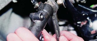
How to pump up a PSU on a KamAZ when nothing else helps. Forcefully depress the clutch fork drive lever. That. Using a crowbar or a powerful pry bar, press out the clutch basket. In this case, the PSU rod that presses on the lever will be released. In this case, just a few presses on the clutch pedal will allow the rod to rest against the lever again, after which the clutch will begin to pump.
Errors when installing parts
I would also like to draw your attention to one detail. There is a rubber seal on the rod of the main working cylinder. It very often breaks and jumps off the stem. But without it, it is almost impossible to bleed the clutch, and therefore you have to constantly check its presence.
It is also worth paying attention to how the PSU is installed. If the installation on KamAZ 5320 does not raise any doubts, then on the 65115 PGU it can be installed and vice versa. And if in doubt, make sure the bypass valve is on top. Otherwise, the clutch will not bleed.
Inspection and testing work
Initially, it is necessary to determine whether the clutch needs to be adjusted and bled. This can be determined by the presence or absence of air leakage. The stronger the leak, the worse the pneumatic hydraulic booster works.
You can check by simply pressing the pedal (the engine must be turned off). If the driver hears a characteristic whistle, this indicates a strong leak. If you cannot detect it by sound, you can apply a soap solution. The appearance of bubbles will indicate a malfunction of the clutch system.
Adjusting clutch free play
Further pumping of the clutch on a KamAZ 65115 vehicle involves carrying out adjustment work regarding the release clutch. The part is installed to disengage the clutch. The amount of free play should be within 3-4 mm. This indicator will correspond to a similar indicator of the fork stroke - it is approximately 4-5 mm. Changing these numbers requires immediate adjustment.
Work order:
- the fork, which deactivates the clutch, is moved to the side, and the spring mechanism is removed;
- the lever stroke is checked manually;
- restoration of the normal motion of the coupling is carried out by adjusting the shaft with a spherical nut, which is part of the pneumatic pusher;
- when the required value is reached, the spring is installed in place.
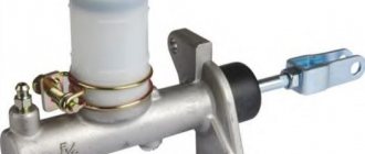
KAMAZ clutch master cylinder design
It is a cylinder body into which a spring is inserted. The spring rests against the cuff and piston. Next comes the rod with an o-ring. The piston limiter is a retaining ring installed inside the cylinder.
Design features
Kamaz clutch As a rule, a dry double-disc (in rare cases single-disc) friction-type clutch is installed on KamAZ vehicles. This device is common in almost all heavy, high-power machines. It requires constant maintenance due to the fact that during operation, due to the great power of the vehicles, these clutches experience enormous loads. So, in what cases does it become necessary to adjust the clutch of MAZ and KamAZ:
- The device clearly slips at high speeds.
- The pedal free play does not meet the standard values.
- A mechanical noise occurs when changing gears.
Clutch adjustment
If you notice even one of the listed signs, it means that the KamAZ clutch basket requires adjustment. If this is not done in time, problems may spread to the gearbox and other transmission parts. In general, proper adjustment of the Kamaz clutch can be divided into 3 main stages:
- Adjusting the pedal free play. The standard value for free play is in the range of 6–12 mm. It should be measured from the middle part of the plate at the moment when the pedal is lowered until you feel resistance when pressing. The free play is adjusted with an eccentric finger - it connects the pusher eye with the pedal lever. The pin should be rotated until the gap between the upper stop and the piston pusher reaches 6–12 mm. Once the desired value is reached, tighten and cotter the castle nut. Afterwards, be sure to measure the full pedal stroke, it should be 185–195 mm.
- Adjusting the clutch free play. The free play should be 3.2–4 mm. Measuring it is not difficult at all. We move the fork shaft lever away from the adjusting spherical nut of the pusher. Don't forget to remove the spring and note that the lever should move a maximum of 4-5mm. If discrepancies with the standards are noticed, the situation can be corrected using a spherical nut. As soon as the lever stroke reaches 4–5 mm, the free stroke of the clutch will automatically take on the desired value.
- Adjusting the full stroke of the booster pusher. It is measured very simply. Depress the clutch until it hits the floor. If the pushrod travel distance is less than 25 mm, first check the pedal free play and the fluid in the master cylinder. If everything is in order there, release the air from the hydraulic system and then everything will return to normal values.
Types of PSU of KAMAZ vehicles
Currently, trucks of the Kama Automobile Plant use several types of CCGT units of domestic and foreign production. They differ in design and applicability.
The CCGT with catalog number 5320 is manufactured at KAMAZ OJSC and has a classic design with a vertical arrangement of the tracking device and the actuating pneumatic cylinder (the tracking device is located above the cylinder body). Used on cars models 5320, 4310, 43118, 55111 and others.
The WABCO PSU is manufactured in the USA, has compact dimensions, and is additionally equipped with a lining wear indicator (allows you to track the life of the amplifier without disassembling it). Used on new models KAMAZ-5460, 6450, 6460, 6520, 6522, 65115, 65116, 65117 and others with gearbox-154 (“Euro-2” and “Euro-3”), as well as on NefAZ buses with the same gearbox .
WABCO PGU for KAMAZ-6460, 6520 and others with ZF gearbox.
WABCO PSU for KAMAZ-4308 vehicles with a 5-speed manual transmission from ZF.
CCGT analogues of WABCO produced by Volchansky Aggregate Plant (Volchansk, Ukraine).
CCGT analogues of WABCO manufactured by Yumak (Türkiye).
When choosing a new amplifier, you need to focus on the brand and catalog number of the unit already installed on the car. Only in this case will the normal operation of the PSU and clutch be guaranteed. It is not recommended to install a CCGT unit of another brand and model; to resolve this issue, you should contact a specialist.
How to know when it's time to change your clutch
There are cases when adjusting the clutch cannot correct the problem. Perhaps you missed a moment when you could get by with little effort, or maybe the device failed for some objective reason. So, it’s time to change the MAZ clutch if you notice the following signs:
- The device turns on abruptly, the car jerks and abruptly pulls away.
- Noise in the mechanism, perhaps a loud cracking sound when the gear is engaged.
- The car starts moving late, even if you release the clutch on time.
- A characteristic burning smell in the cabin (this is a clear sign that the clutch has burned out).
There is no need to delay replacing the clutch. As a result, everything may end in damage to the gearbox or in the fact that one fine day the car simply will not be able to move.
You should take on the work yourself only if you know exactly the sequence of actions. Otherwise, it is better to contact specialists.
However, if you are confident in your abilities or the KamAZ clutch basket is familiar to you, you can get down to business.
Filling the clutch release hydraulic system with working fluid
Only special brake fluid is poured into the clutch release hydraulic drive system (TU MXP 1608-47, TU 35-ХП-430-62 or TU 35-ХК-482-64).
You cannot mix brake fluids of different brands and add to the system even the smallest amount of mineral oils, glycerin, gasoline, kerosene or mixtures thereof, which cause swelling and then complete destruction of rubber parts and, as a result, failure of the system. The use of ethylene glycol is also unacceptable due to the corrosion it causes to metal parts.
If special brake fluid is not available, you can use a mixture of 50% (by weight) castor oil and 50% butyl alcohol. It is possible to replace butyl alcohol with isobutyl or ethyl alcohol. It is important to keep in mind that ethyl alcohol evaporates more easily than butyl alcohol, and the composition of the mixture will change (especially in hot weather).
When switching to a different type of working fluid, it is necessary to remove the old one and thoroughly rinse the entire hydraulic clutch system with alcohol or new brake fluid. Brake fluid is poured into the body of the nutrient tank 3 without removing the strainer 2 from it in order to avoid foreign impurities entering the system. The brake fluid level should be 10-15 mm below the top edge of the reservoir.
It must be remembered that brake fluid leaves stains on the painted surface of the car body; therefore, you need to fill the system carefully, avoiding liquid getting on the body.
It is very easy to monitor the liquid level in the nutrient tank, since the tank is made of translucent plastic.
It is necessary to fill the hydraulic clutch release system with brake fluid and remove air from it in the following order:
- Fill the reservoir with liquid through a strainer to the normal level. To fill the tank faster, it is recommended to slightly raise the strainer.
- Clean the air release valve on the working cylinder from dust and dirt and, having removed the rubber protective cap 2 from the valve head, put a rubber hose (included with the car) on the valve head. Immerse the free end of the hose in brake fluid poured into a clean glass container with a capacity of at least 0.5 liters, which must be filled to half its height.
- Press the clutch pedal sharply with your foot 4-5 times in succession (with an interval of 1-2 seconds between presses), and then, leaving the pedal pressed, unscrew the air release valve 1/2-1 turn. Under the influence of the pressure created in the system, part of the liquid and the air contained in it will be released through the hose into the container with the liquid (the air will come out of the hose in the form of bubbles).
- After the liquid flows out of the hose stops, turn the air release valve all the way.
- Repeat operations 3 and 4 until the release of air from the hose immersed in a vessel with liquid completely stops (this will require up to 75-80 pedal presses).
During the operation of removing air from the hydraulic drive system, add brake fluid to the nutrient tank, preventing the level in it from decreasing by more than 2/3 of the normal value. Insufficient height of the liquid column above the bypass and compensation holes in the master cylinder body can lead to atmospheric air being sucked into the cylinder (and into the system).
Disassembling the cylinder
The cylinder can be disassembled from both sides.
- The retaining ring is removed from inside the cylinder. The spring will push the cuff and piston out. This disassembly method is very inconvenient; it is difficult to get the locking ring. But if you don’t want to remove the cylinder completely to replace the cuff, you can use it. If the cylinder stops working due to wear. Of course you will have to suffer.
- If the cylinder is removed. The easiest way is to unscrew the bottom plug. To which the tube is screwed. The cylinder is clamped in a vice and the plug is unscrewed. the spring and the cuff with the piston come out.
The cylinder is disassembled to replace the cuff. But this does not always lead to the desired result. In addition to the fact that the cuff becomes unusable. The piston and cylinder walls wear out. Uneven output is formed. Ovality. Or large grooves. The cuff no longer fits tightly to the walls of the cylinder. Therefore, after installing a new cuff, the cylinder remains faulty. When disassembling the cylinder, it is necessary to check the condition of the piston and cylinder walls. If wear is visible to the eye and to the touch, it is better to replace the cylinder with a new one.
Amplifier operating principle
The pneumatic hydraulic booster works in the clutch system so that the mechanism neutralizes the pressure exerted by the driver when pressing the pedal. By squeezing the accelerator, the fuel moves the pistons mounted on the amplifier. When pressed, the piston moves down, opening the intake valve. The hole allows air flow to reach the level of the pneumatic piston, and the pusher retracts the fork, which acts on the clutch.
The nature of the press determines the state of the clutch system. If the pedal fails, it means that an air cushion has formed in the accelerator. If the clutch system is not repaired in time, the transmission may subsequently suffer.
To identify the problem as quickly as possible, clutch diagnostics should be carried out as often as possible. Timely checking of one unit can save the “life” of the entire gear shift mechanism.
- Initially, you need to determine how much it is necessary to pump the CCGT unit. The main indicator will be the absence or presence of air leaks. If the leak is severe, then the air-hydraulic booster is not working well.
- The test is carried out by pressing the pedal with the engine turned off. If you hear a characteristic whistle, it may be due to a leak. Sometimes it can be difficult to determine the presence of extraneous noise by ear, then you can use a soap solution. It is applied to the site of the suspected leak; if bubbles appear, it means the clutch system was faulty.
- Before pumping begins, the PGU system is secured with bolts. The tank containing the hydraulic fluid is checked to ensure there is the required amount.
- It is necessary to check the springs for adjusting the movement of the clutch mechanisms; if they are stretched, they should be replaced.
If the CCGT system is faulty, it needs to be bled. This service is available at absolutely all Kamaz service centers, however, it is quite possible to do it yourself. Bleeding is possible if the hydraulic booster itself is in working condition.
- Adjust the free play of the pedal. The ideal amplitude should be 1.5 cm. It is easy to check: place a ruler under the pedal, depress the pedal, and you can see what part of the pedal “travel” is. We leave the pedal in the highest position, loosen the crown nut to allow the eccentric pin to move freely, rotate the pin, after which the gap decreases, fix the gap to approximately 0.6-1.5 cm, then tighten the nuts. The pedal itself is set at around twenty centimeters, not less than eighteen centimeters. The adjustable movable stop at the top of the accelerator pedal will help correct the position of the pedal.
- We adjust the free play of the clutch. The bleeding process continues with adjustment work around the release clutch. It is necessary when disengaging the clutch; it has a free play of approximately 3-4 mm. With this clutch indicator, the fork stroke is 4-5mm. If the indicators have a different meaning, they need to be adjusted. To do this, the deactivation fork is moved to the side to remove the spring mechanism. Lever travel can be checked manually. The shaft is adjusted using a spherical nut, which is part of the pneumatic pusher. After reaching the required amplitude, the spring is fixed.
- We adjust the full stroke of the pusher. The normal value for this system is 2.5 cm. At lower values, it will be problematic to depress the clutch normally. Initially neglected full speed problems entail problems in the operation of the gearbox. You can check the operation of this unit by pressing the pedal all the way. If the stop is insufficient, you can check the presence of fluid in the tank, or adjust the free play again. The last, third stage of adjustment ends with pumping.
After going through all the preparatory steps, you can try to bleed the system yourself.
COOLANT
Coolant is a balanced mixture of antifreeze and water. The presence of antifreeze allows you to expand the range of operating temperatures, lowering the freezing point and increasing the boiling point of the coolant. The additives included in antifreeze protect the engine cooling system from cavitation corrosion. Coolants based on ethylene glycol are approved for operation of KAMAZ engines. The list of coolants approved for use in the cooling system of KAMAZ engines is given in tables B.8, B.9. The use of coolants is mandatory in all climate zones. In a temperate climate zone, it is recommended to use coolants with an antifreeze concentration of 40% (OZh-40 “Lena”, “Tosol-A40M”, “Cool Stream Standard 40”, etc.). In cold climate zones, it is recommended to use coolants with an antifreeze concentration of 65% (OZh-65 “Lena”, “Tosol-A65M”, etc.). During operation, it is necessary to monitor the density of the coolant. Thus, the density of the coolant at a temperature of 20 °C should be:
- Coolant-40 “Lena” - (1.075 - 1.085) g/cm 3 ;
- “Cool Stream Standard 40” - (1.068 - 1.070) g/cm 3 ;
- “Tosol-A40M” - (1.078 - 1.085) g/cm3;
- Coolant-65 “Lena” and “Antifreeze -A65M” - (1.085-1.1) g/cm 3 ;
- “Antifreeze (-45) FELIX®” - (1.065-1.085) g/cm3;
- Antifreeze “X-Freese Carbox” G12 - (1.065-1.085) g/cm 3 ;
- Coolant -40 “TORSA-TOSOL-103” - (1.075-1.085) g/cm 3 ;
- SINTEC Antifreeze-40 - (1.065-1.085) g/cm 3 ;
- “KAMAZ-STANDARD 40” - (1.068 - 1.072) g/cm 3 ;
- “KAMAZ-STANDARD 65” - (1.083 - 1.085) g/cm 3 .
If the density of the coolant is below the minimum permissible value, the fluid must be replaced. If the coolant density is higher than the maximum permissible value, the coolant density should be adjusted by adding demineralized water. Coolants ES Compleat and Old World Fleet Charge Coolant are recommended for refilling the cooling system of Cummins engines. Old World Fleet Charge finished products are available with varying antifreeze contents. Coolant Old World Fleet Charge Coolant 50/50 (antifreeze content - 50%) is operational down to minus 37 ° C; Old World Fleet Charge Coolant 60/40 (antifreeze content - 60%) is operational down to minus 52 °C. Finished ES Compleat products are available with different antifreeze contents. Coolant ES CompleatTM EG Premix 50/50 (antifreeze content – 50%) is operational down to minus 36 °C; ES CompleatTM EG Premix 60/40 (antifreeze content – 60%) is operational down to minus 54 °C.
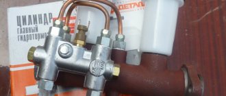
Two features of the KAMAZ clutch master cylinder
- A check valve is installed in all master cylinders, both clutch and brake. In order for the valve to close when pressed and create an axis of fluid pressure. When you release the pedal, the valve opens and allows the fluid to return back to the expansion tank. The role of the valve is performed by a membrane installed between the cuff and the piston. The piston has holes. Through which the fluid returns.
On the Kamaz clutch master cylinder, the role of the valve is played by the rod. There is a hole in the piston. When you press the pedal, the rod closes the hole. The rod at its base has a rubber sealing ring. Thanks to which the liquid is held under pressure. When releasing the pedal. The hole in the piston opens. The liquid from the PSU returns to the expansion tank.
CCGT pumping
An experienced mechanic will pump the PSU on his own; a less experienced specialist would be better off taking a partner. The pumping process, which is essentially also a cleaning process, consists of several important steps.
- Initially, it is necessary to thoroughly clean the system from dust, dirt, grease deposits and lubricants. After cleaning, a special hose is put on the valve, the second end of which is lowered into a container with working fluid.
- It is necessary to sharply press the clutch pedal all the way several times, after which during the last press it must be fixed in the depressed position. When pressed, the bypass valve rotates, and the liquid inside the air-hydraulic booster will begin to flow under pressure into the container. At this stage, it is easy to determine whether there is air in the system - by the presence or absence of bubbles.
- The PSU is pumped several times until there are no bubbles at all. After finishing the work, the bypass valve is screwed on, the hose is disconnected, and the rubber cap is put on.
- It is imperative to replenish the tank with working fluid, the level of which must be at least four centimeters from the edge.
Some masters bleed the clutch without a container, using a regular pump; some, on the contrary, use only glass containers. Pumping will give positive results if it is carried out correctly, performing all the work step by step.
Motor oils for Kamaz engines
When carrying out maintenance of KAMAZ engines, it is recommended to use high-quality motor oils “KAMAZ OPTIMUM S AE 5 W-40, 10W-40, 15W-40” STO 00148636-006-2007 as amended. 2 or similar from the list of motor oils given on the official website www.kamaz.ru. Depending on operating conditions, it is recommended to use motor oils of the following SAE viscosity classes:
- SAE 5W-30, 5W-40 (all-season operation in areas with cold climates);
- SAE 15W-40, 10W-40 (all-season operation in temperate climate zones);
- SAE 20W-50 (all-season use in tropical climates).
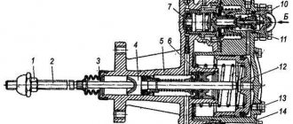
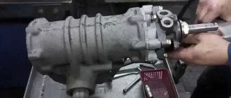
Dismantling of PGU KamAZ 5320
If malfunctions occur, it is necessary to disassemble the amplifier 1609510. Disassembly is carried out in the following sequence:
- The half of the body, in which the pneumatic cylinder is located, is rigidly fixed;
- The housing mounting bolts are unscrewed, the clutch release lever drive rod is dismantled;
- The valve is removed from the body;
- Remove the front part of the body;
- The pneumatic cylinder piston and flexible diaphragm are dismantled;
- The retaining ring is removed;
- The valve mechanism reducer is removed;
- Half of the body is removed from the vice;
- The follower piston and the stopper securing it are removed.