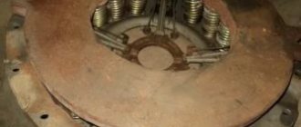
Repair of pressure regulator of the pneumatic system (“unloading”) of KamAZ, ZIL, KrAZ vehicles
Main malfunctions of the pressure regulator:
- stopping the air supply to the system
Air leakage from the pressure regulator itself:
- if the pressure in the pneumatic system drops sharply at idle, the check valve is faulty.
- air comes out of the "pumping" valve.
The main malfunction of the regulator is the destruction of the rubber heads of the bypass valve:
- If, when pumping air, the regulator begins to operate at 2-4 atmospheres, then, most likely, this is caused by the destruction of the lower valve head, or, less often, the sealing ring of the narrow part of the piston.
- If the compressor pumps “all the way” and a hissing sound is heard from the top cover, this is a defect in the upper head of the bypass valve or the piston sealing collar.
Removing the pressure regulator
A similar pressure regulator is installed on KamAZ, ZIL and KrAZ vehicles. It is located on the right side of the frame behind the cab. For dismantling you need:
- Use a 22mm wrench to unscrew the two air lines
- wrench 13 – bolts securing the regulator to the frame
When the unloading is removed, clean it of dirt and secure it in a vice.
Disassembling the lower part of the pressure regulator
Using a 50mm wrench, unscrew the bottom cover.
Remove the filter and preload spring. The entire unloading valve mechanism is located in the cover. We check the condition of the o-ring of the unloader valve piston and replace it if necessary.
To do this, remove the retaining ring and remove the valve assembly with the seat.
- Use 10mm wrenches to unscrew the locknut
- Unscrew the second nut by inserting a suitable wrench into the hole in the valve rod.
The connection between the valve and the rod must be tight. To separate them, you need to apply force, but do not deform the valve. Eliminate shallow defects in the rubber surface of the valve by grinding the entire surface using a fine-grained abrasive wheel.
When connecting the valve to the rod, use sealant.
Disassembling the upper part of the pressure regulator
Using keys 17, loosen the lock nut, and with keys 12, unscrew the adjusting bolt.
Clamp the regulator in a vice. Using a 50mm wrench, unscrew and remove the spring with the thrust plate and guide assembly.
Grasp the piston from the inside and remove it.
Check the condition of the cuff. If necessary, replace it by installing it with the forked end down.
You can disassemble the check valve by unscrewing the support washer with narrow-nose pliers.
Remove the spring with the valve.
Using a 24mm wrench, unscrew the tire inflation device and remove it as an assembly.
If air comes out of the priming valve, replace the two o-rings.
Source
Double safety valve Kamaz
The double safety valve (Fig. 1 a) is designed to divide the supply line into two autonomous circuits (auxiliary and parking brake) and automatically turn off the damaged circuit in order to maintain the required pressure in the healthy circuit.
It consists of a housing 1, a central piston 2 with two check valves 3, two thrust pistons 4 and springs 5, 6, 7, respectively, thrust pistons, a central piston and check valves.
In the initial position before starting work (Fig. 1 b), the central piston 2, under the action of springs 6, occupies the middle position.
In the operating position (Fig. 1, c), when air is supplied from the condensation receiver to inlet I , compressed air through the hole in piston 2 presses the check valves and flows to outputs II and III .
If one of the circuits is damaged (Fig. d), the pressure in it drops and the central piston 2, under the influence of the pressure difference, moves towards the damaged circuit, its seat rests against the check valve 3 and presses it against the piston 4, turning off the damaged circuit.
The check valve of the secondary circuit remains open, and compressed air from the supply line continues to flow into the undamaged circuit.
A double safety valve, if one circuit is faulty, maintains the compressed air pressure in good working order within the range of 520.540 kPa.
When the pressure at the valve inlet increases above 540 kPa, spring 5 is compressed under the action of compressed air acting on check valve 3, the valve is torn off the seat and excess compressed air is released into the damaged circuit.
Source
Description of the Kamaz pneumatic braking system
The basis for starting and stopping the air braking system is the circulation of compressed air. It is stored in special tanks. The circulation of compressed air is ensured by the operation of the compressor.
The brake operation diagram looks like this:
- Under conditions of increased pressure, a certain amount of air enters the compressor from the tank.
- After the brake system is activated, the operating torque is transmitted to the brake valve, which increases the pressure in the brake chambers.
- They are activated by a special lever, which is the key mechanism of the braking system.
- When the brake pedal is lowered, all parts return to their original position.
The backup brake works in a similar way. It is necessary to carry out maintenance of the brake system every 4 months.
Double-line valve Kamaz
The two-line bypass valve (Fig. 1) is designed to control one actuator (spring energy accumulator) through one of two independent circuits of your choice
It consists of a body 1 with a cover 3, a seal 2 and two seats in them.
Terminal I of the valve is connected to the accelerator valve line, terminal II is connected to the spring energy accumulator line, terminal III is connected to the emergency brake release valve line.
When the car is released with a manual brake valve (Fig. 1. b), compressed air from the parking brake receiver is supplied through the accelerator valve to terminal I, pressing seal 2 to the seat of cover 3, and then through terminal II enters the cylinders of spring energy accumulators.
When the car is released using the emergency brake release valve (Fig. 1. c), compressed air is supplied to terminal III and seal 2 is pressed against the seat in housing 1.
The car is braked by releasing compressed air from spring energy accumulators, while seal 2 remains pressed to the seat and air freely passes through terminal II to terminal I or III.
When compressed air is simultaneously supplied to terminals I and III, seal 2 can occupy a neutral position.
Control and warning devices
The monitoring and warning device is a mechanism that serves to indicate a signal for increasing or decreasing pressure. The RDV adjustment is carried out using multi-colored lamps and a special signaling sound. This way the work of the main warning system is relieved. If there is a problem with its operation, it is enough to reset the settings and adjust the device again. Emergency alert works based on sensors installed in the brake system. If a problem occurs, the signal is immediately transmitted to the dashboard.
Performance indicators
The main operating parameters of the KamAZ 65115 and 5320 brake system are presented below:
- brake pad size is 400mm;
- the area of the brake seals is 6.3 square meters;
- The brake is controlled using a pedal;
- the brake chamber is type 24;
- the mechanism that controls pressure differences has two cylinders;
- the maximum air supply in the device is 220 liters per minute;
- number of air cylinders - 5 pieces;
- The volume of air cylinders is 120 liters.
6520-3513023 Receiver assembly with connecting fittings KamAZ-6520 (Euro-4). Catalog 2016
Attention: The electronic auto parts catalog is intended for reference purposes! Our company only sells those products that have prices listed.
| Number | 6520-3513023 |
| Name | Receiver |
| Quantity per "Quantity" | 1 |
| Model | 6520 |
| Group | Brakes |
| Subgroup | Air cylinders for pneumatic brakes |
| Part serial number | 023 |
Serial number: 6520-3513023 Quantity per model: 1
| Number | 6520-3513024 |
| Name | Receiver |
| Quantity per "Quantity" | 1 |
| Model | 6520 |
| Group | Brakes |
| Subgroup | Air cylinders for pneumatic brakes |
| Part serial number | 024 |
Serial number: 6520-3513024 Quantity per model: 1
| Number | 65115-3513017 |
| Name | Receiver with bracket |
| Quantity per "Quantity" | 1 |
| Model | 65115 |
| Group | Brakes |
| Subgroup | Air cylinders for pneumatic brakes |
| Part serial number | 017 |
Receiver with bracket
Serial number: 65115-3513017 Quantity per model: 1
How to adjust air pressure
In order to adjust the air pressure, it is necessary to install the vehicle on an inspection hole or a special platform for repair work.
Adjustment of the mechanism is carried out only when the power unit is turned off.
The whole process takes place in 3 stages: disassembly, adjustment and installation.
In order to dismantle the regulator, you need to unscrew the lock nut and turn out the adjusting screw. This will help loosen the counterbalance type piston springs. After this, use a special socket wrench to pull out the spring device, unscrew the protective cover and remove the sealing collar.
In order to remove the muffler, you need to unscrew the fasteners from the bottom of the cover and pull out the filter element. Then remove the 2 o-rings and the relief piston. After dismantling, it is recommended to wash all parts with clean gasoline.
After these steps, you should install the regulator on a special test stand and connect the device according to the diagram given in the user manual.
After connection, it is necessary to apply compressed air at a pressure of at least 1.4 MPa to the terminals 3 times.
If the limits of the regulated pressure exceed 0.8 MPa, you need to use a bolt to adjust the pressure level to the required limits.
Upon completion of the adjustment, you should check the level of pressure on and off the regulator 3 times, after which you can lock the bolt.
Malfunctions and repairs
Main malfunctions and repairs of the regulator:
- If air leaks from the atmospheric outlet, the valve body must be cleaned or the defective valve and O-ring must be replaced.
- The device has stopped switching the compressor to idle mode. This problem can be caused by a clogged channel, pinching of the piston, or damage to the cuff. It is recommended to clean the valve, conduct an external inspection of the cuff and, if necessary, replace it with a new one, and also update the piston.
- The regulator stopped switching the compressor to the mode of filling the system with air. This malfunction is associated with clogged atmospheric orifice and intake valve, damaged spring, worn O-ring, tight piston part and worn valves. It is necessary to conduct an external inspection of the entire system for damage and defects, and if necessary, replace failed spare parts.
- Air leakage through the outlet into the atmosphere can be eliminated by replacing the filter element.
- When there is no supply of compressed air flow to the brake system of a vehicle, it is necessary to clean the check valve from accumulated contaminants or replace it if worn.
- If there is a small shaft between the on- and off-pressure level of the regulating device, damaged cuffs and rings should be replaced, valves and seats should be inspected and cleaned.