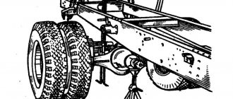
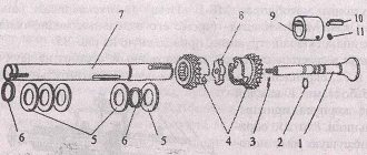
6.2. Clutch and reduction gear. Malfunctions and their elimination.
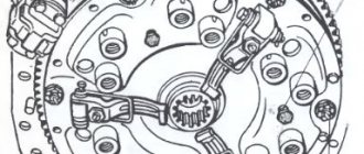
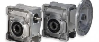
Rice. 2.5.6. Clutch and reduction gear: a - general view; b - relative position of parts; 1 - damper; 2 — driven disk; 3 — pressure disk; 4 — support disk; 5 — release lever; 6 — thrust bearing; 7 - layering; 8 — layering bracket; 9, 15, 16, 26, 39, 40, 54, 58, 62 - rings; 10 - cuff; 11 — oil deflector washer; 12, 14, 18, 27, 29, 38, 56, 61 - bearings; 13 - thrust bushing; 17 — intermediate gear; 19 — gear axis; 20 — fixing screw; 21 — clutch housing; 22, 50, 63 — gaskets; 23, 24 — covers; 25 — power take-off shaft (PTO) drive shaft; 28 — thrust washer; 30 — brake lifting bracket; 31 — power plug; 32 — brake release; 33 — brake disc with lining; 34 — gear coupling; 35 — clutch shaft; 36 - gear; 37 — support cover; 41, 44 — levers; 42 — clutch fork shaft; 43 — brake rod; 45 — power fork shaft; 46 — clutch cover; 47 — power take-off shaft (PTO) gear shift fork; 48 — power take-off shaft (PTO) gear shift shaft; 49 — bottom cover; 51 — needle bearing; 52 — power take-off shaft (PTO) drive shaft; 53 - coupling; 55 — power take-off shaft (PTO) drive gear (II stage); 57, 60 — spacer washers; 59 — power take-off shaft (PTO) drive gear (I stage); 64—bearing cover.
Most malfunctions of the reduction gear switching mechanisms are associated with the occurrence of the following main defects: spontaneous shutdown and difficult gear shifting, the appearance of noise and knocking. (Fig. 2.5.6) The gears switch off spontaneously due to wear and chipping of the teeth of the gears and gear couplings, wear of the clamps and recesses for them on the rollers of the gear shift mechanism, loss of elasticity of the springs of the clamps, wear of the friction surfaces of the shift forks, the rocker, the annular grooves of the sliding gears and gear couplings. Stiff shifting of gears and their inclusion with a grinding noise occur (along with incomplete disengagement of the clutch) when the brake adjustment is violated or the locking mechanism does not work properly. Increased noise and knocking in the gearbox occurs due to wear of the shaft bearings, bearing seats in the housing, misalignment of the shafts, insufficient oil in the gearbox housing, cracks and broken parts. The noted malfunctions arise not only due to fatigue wear of mechanical parts, but also due to improper operation and non-compliance with technical conditions during repairs. Thus, increased wear of bearings and gear teeth in thickness can be caused by the presence of abrasive particles in the oil poured into the gearbox housing, or the entry of such particles into the lubricant through leaks. Chips and destruction of gear teeth on the engagement side appear due to inaccurate adjustment of the clutch, incorrect gear shifting, and improper adjustment of the clutch shaft brake. Fatigue chipping of gear teeth is significantly accelerated by incorrect meshing of gear pairs, their incomplete engagement, or inaccurate adjustment of the meshing of bevel pairs. During operation, a number of malfunctions can be eliminated directly on the tractor.
Gearbox and PTO control Belarus MTZ-82.1
Gear shift
The Belarus MTZ-82.1, 80.1, 82.2 tractors with the basic configuration are equipped with a mechanical stepwise dual-range gearbox, with one range and gear shift lever located under the operator’s right hand with a mechanical reduction gearbox (18F+4R).
It is possible to install transmissions with the following configurations:
— with a manual transmission and synchronized reduction gearbox (18F+4R); — with a manual transmission and reverse gearbox (9F+9R).
Gear shifting in a transmission with a manual gearbox and a mechanical or synchronized reduction gearbox.
The controls for a manual transmission with a mechanical or synchronized reduction gear are shown in the figure.
Fig. 1 - Control of the Belarus MTZ-82-1, 80-1, 82-2 checkpoint
1 – diagram of switching stages of the reduction gearbox; 2 – reduction gear control lever; 3 – range and gear shift lever; 4 – scheme for switching ranges and gears.
Gear shifting is carried out by two levers: the transmission range and gear shift lever and the reduction gear control lever 2.
The selection of the required ranges, gears and stages of the reduction gear (the decelerating stage is the “turtle” symbol, the accelerating stage is the “hare” symbol) is made in accordance with switching patterns 4 and 1.
Switching ranges and gears is done with one lever 3, and first the range (1st or 2nd) is turned on, then the lever is moved to the “N” position, and the selected gear is engaged.
The control lever of the mechanical reduction gearbox 2 must be in the on (fixed) position during tractor operation: backward - accelerating stage ("hare"), or forward - decelerating stage ("turtle").
The control lever for synchronized reduction gearbox 2 must be in the on (fixed) position while the tractor is operating: backward - decelerating stage ("turtle"), or forward - accelerating stage ("hare").
It is possible to hold the reduction gear lever in the neutral (middle non-fixed) position to facilitate engine starting at low temperatures.
Gear shifting in a gearbox transmission with a reverse gearbox
The control elements of the Belarus MTZ-82.1, 80.1 gearbox with a reverse gearbox are shown in the figure.
Rice. 2 - Gearbox control
1 – diagram of switching stages of the reverse gearbox; 2 – reverse gear control lever; 3 – range and gear shift lever; 4 – scheme for switching ranges and gears.
Gear shifting is carried out by two levers: the range and gear shift lever and the reverse gear control lever 2.
The selection of the required ranges, gears and reverse gear stages (forward stage - “forward” symbol, reverse stage – “backward” symbol) is made in accordance with switching patterns 4 and 1.
Switching ranges and gears is done with one lever 3, and first the range (1st or 2nd) is turned on, then the lever is moved to the “N” position, and the selected gear is engaged.
The reverse gear control lever 2 must be in the on (fixed) position while the tractor is operating: forward – forward gear (“forward”), or backward – reverse gear (“backward”). It is possible to hold the reverse gear lever in the neutral (middle non-fixed) position to facilitate engine starting at low temperatures.
PTO control
On Belarus MTZ-82.1, 80.1 tractors, a rear power take-off shaft is installed as standard. A side semi-independent PTO can also be installed.
Rear PTO control
Handle for switching rear PTO from independent to synchronous drive
When moving handle 11 to the extreme left position (along the path of the tractor), the synchronous drive is activated, to the extreme right - independent, to the middle - the “neutral” position.
Engaging the rear power take-off
Engaging the rear PTO Belarus MTZ-82-1, 80-1 is possible only if handle 11 is set to the “synchronous drive is on” position or to the “independent drive is on” position. In the “neutral” position, the rear PTO does not work.
The rear PTO 5 engagement lever has two positions:
— when lever 5 moves from the extreme forward position to the extreme rear position, the rear shaft is engaged; — when lever 5 is moved from the rearmost position to the frontmost position, the rear shaft is switched off.
It is recommended to turn the rear PTO on and off while the engine is running. In the figure, lever 1 is set to the “off” position.
Rice. 3 — Rear PTO connection diagram Belarus MTZ-82.1, 80.1
1 – rear PTO engagement lever; 2 – instruction plate for rear PTO control.
Switch for two-speed independent rear PTO drive
The driver of the independent PTO 2 drive has two positions:
– I – 540 min-1) – extreme, clockwise; - II - 1000-1) - extreme counterclockwise.
To set the desired rotation speed, unscrew bolt 1 by one turn, turn driver 2 to position “I” or “II” and tighten bolt 1.
Rice. 4 — Switching the rotation speed (bottom view of the transmission)
Operation of Belarus MTZ-82.1, 80.1 tractors without using a rear PTO
When operating the tractor without using the rear PTO, the switch lever for the independent two-speed shaft drive must be set to the 540 min-1 position, the rear PTO switch handle from independent to synchronous drive must be set to the neutral position, and the rear PTO engagement lever must be set to the “off” position.
The rear shaft guard protective cap must be installed.
Side semi-independent power take-off shaft control
The side semi-independent power take-off shaft Belarus MTZ-82-1, 80-1 is controlled by a rod, which is located on the left side of the operator’s seat.
The rod has two fixed positions:
— “on” – top position; - “off” – lower position.
The lateral semi-independent PTO at rated engine speeds has the following rotation speeds:
— 571 min-1 – with the reduced stage of the reduction gear (“turtle”) turned on; — 755 min-1 – with the increased stage of the reduction gear (“hare”) turned on.
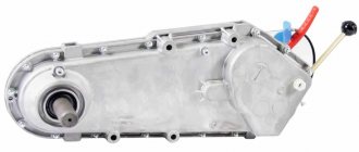
Functions and design of a mechanical creeper
Based on the principle of operation and control, MTZ creepers are divided into mechanical and hydraulic; in practical work, both modifications are used with equal success.
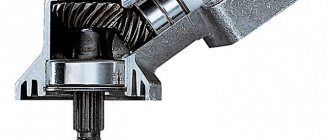
A planetary gear reducer is used as a mechanical speed reducer, the gear ratio of which is 7.104. The mechanism is assembled in a steel case, and the design of the tractor gearbox provides for the installation of this unit on the left side hatch of the gearbox on the side of the front axle.
Creeper mechanism
The kinematic diagram of the unit includes an intermediate and gear shaft, a planetary gearbox and a position switching mechanism with a lever located in the cabin next to the steering column.
The torque in the circuit is taken from the mounting location of the side power take-off shaft (PTO) of the main gearbox (from the left along the tractor) and is transmitted through a set of gear wheels to the gearbox for engaging the speed reducer of the main gearbox and to the low gear shaft. The control lever in the “off” and “on” positions is fixed using a spring mechanism.
The control mechanism includes a fork and a pusher roller; when the lever is turned on, axial movement of the intermediate gearbox sprocket is ensured to engage or disengage with the gearbox gear reducer.
Before starting to move, first of all, using the lever, the creeper is switched on, then the selected gear of the main tractor box. The direction of rotation of the output shaft of the box when transmitting torque through the speed reducer changes to the opposite, therefore, when the second and first gears and reverse are engaged, the tractor will begin to move forward, and vice versa.
The control of the gearbox for the remaining stages does not depend on the speed reducer; when switching to them, it should be turned off.
Reduction gear
The MTZ-82 gearbox provides 9 speed levels for the forward movement of the tractor and 1 speed for the rear. Thanks to the presence of a reduction gearbox in the transmission, which provides an additional reduction gear for each stage, the number of available speeds is doubled.
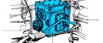
This mechanism is structurally mounted in the same housing with the clutch mechanism, and in the kinematic diagram it is located between the clutch and the gearbox.
The low gear in this device is provided by 2 pairs of gears with a gear ratio of 1.34. The reduction gear is switched on and off using a gear coupling mounted on the splined end of the shaft.
The reduction gearbox is structurally located in the tractor clutch housing.
Depending on its position, the clutch and gearbox shafts can be connected directly; in this case, the reduction gear is disabled; when turned on, the clutch moves until it engages with the small ring of the drive gear and the torque from the clutch shaft is transmitted to the gearbox at a reduced speed.
The reduction gearbox is controlled by a shift lever located in the driver's cab and having 2 fixed positions. The forward position of the lever in the direction of travel corresponds to the on state of the downshift, the rear position corresponds to the off state.