The simplest carburetor
The process of preparing a combustible mixture from finely atomized fuel and air, which occurs outside the cylinders, is called carburetion, and the device in which a combustible mixture of a certain composition is prepared depending on the operating mode of the engine is called a carburetor. The simplest carburetor consists of an air pipe, a float chamber with a float and a needle valve, a mixing chamber, a diffuser, a main metering device - a sprayer and a fuel nozzle, and a throttle valve. The float chamber serves to maintain a constant fuel level at the atomizer (1.5-2 mm). In the mixing chamber, fuel vapors are mixed with air, forming an air-fuel mixture. The atomizer (thin tube) serves to supply fuel to the center of the mixing chamber. The nozzle (calibrated hole) meters the amount of fuel passing to the atomizer.
Float chamber
One of the criteria for proper carburetor operation is accurate adjustment of the fuel level in the float chamber. Fuel is supplied through the fuel line channel to the float chamber. The fuel level in the float chamber is maintained using a float device with a needle valve. After filling the chamber, the float raises the needle and stops the flow of gasoline, while the displaced air is discharged through the hole provided for this purpose. The sprayer and the float chamber are communicating vessels. The fuel level in the float chamber should be slightly below the nozzle exit.
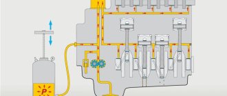
Carburetor engine intake system
1 - pipeline; 2 — hole in the float chamber; 3 - diffuser; 4 - sprayer; 5 - throttle valve; 6 - mixing chamber; 7 - jet; 8 — float chamber; 9 — float; 10 - needle valve.
A diffuser (a short pipe narrowed inside) increases the speed of air flow in the center of the mixing chamber, thereby increasing the vacuum at the nozzle of the sprayer.
The throttle valve regulates the amount of combustible mixture supplied to the engine cylinders, reducing or increasing the flow area of the mixing chamber.
The simplest carburetor works as follows. During the intake stroke, due to the vacuum created by the piston, air enters the diffuser through the air pipe. In the diffuser, the air speed, and therefore the vacuum, increases. Under the influence of the pressure difference between the float chamber and the diffuser, fuel enters the diffuser through the atomizer nozzle, is picked up by the air flow, atomized and evaporated, forming an air-fuel mixture. From the mixing chamber, the combustible mixture enters the engine cylinders through the intake pipe. As the throttle valve opens, the air flow speed and the vacuum in the diffuser increase, which increases fuel consumption. However, the necessary increase in fuel consumption does not occur; the combustible mixture becomes richer. When the engine operates in various modes, the simplest carburetor cannot provide a combustible mixture of a constant composition.
Diffuser
Diffuser - represents the narrowing area of the mixing chamber. The air entering the engine increases speed in the diffuser, as a result of which a vacuum is formed at the sprayer. Under the influence of this difference, fuel is supplied from the atomizer and actively mixed with the air flow. Gasoline from the float chamber enters the atomizer through a channel. A nozzle is screwed into the channel - a screw with a through hole of strictly calculated diameter and shape. The nozzle is responsible for the speed at which gasoline is transferred to the atomizer.
The principle of operation and design of a simple carburetor
In the first device, invented by L. Christoforis in 1876, the fuel was heated, evaporated, and the resulting vapors and air flows were mixed. A year later, the solution was improved using the principle of fuel atomization, which became the basis for subsequent projects.
Before the widespread use of devices familiar to us, there were bubbling and membrane-needle models. The first were in the form of a gasoline tank, in which a board and a pair of pipes were located close to the surface for supplying a mixture of fuel and air from the atmosphere and taking it into the engine. The air moved under the board, directly above the fuel, became enriched in vapor and became a combustible mixture. It was a simple but working system. The throttle valve was located separately. The functioning of the motor with a bubbler unit was influenced by natural conditions - evaporation depended on temperature. Such a system was difficult to regulate and was explosive.
Diagram of a bubble carburetor.
The membrane-needle device is located separately from the gas tank. It contained several chambers, rigidly connected using a rod. The valve seat through which fuel was supplied was locked with a needle on the stem. The chambers were connected by a fuel channel and a mixing zone. The parameters of the device were determined by the springs on which the membranes were pressed. Such a carburetor worked regardless of street conditions and location; it was popular in the early 19th century, when it was installed on cars and motorcycles, and in airplanes with piston internal combustion engines.
Diagram of a membrane-needle carburetor.
Was there an automatic choke?
Of course he was. As for domestic cars, he first used it on the Solex 21083 carburetor, but it was installed only on export VAZ 2110. The essence of its work was as follows - a special spring controlling the damper was connected to the coolant. The bimetal changed its properties as it warmed up, and, accordingly, opened or closed the damper depending on the temperature of the antifreeze.
There have also been developments for our country - this is an electronic suction control system. Instead of a cable, an electric drive was installed, and there was a programming button and a control unit in the cabin. First, the operation of the choke was programmed, and then it closed the damper based on the program. But each season had to be reprogrammed anew, because what worked in the summer, in the winter already required a different open time.
The structure of the carburetor today
Today, float models are used, which are the most advanced. They can be seen on most cars.
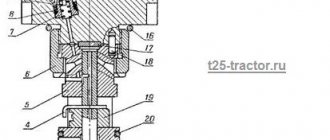
Design and operation of the carburetor: 1 - adjusting screw of the starting device; 2 — lever pin 24, included in the groove of lever 3; 3 — air damper control lever; 4 — screw securing the air damper drive rod; 5 - adjusting screw for slightly opening the throttle valve of the first chamber; 6 — throttle lever of the first chamber; 7 — axis of the throttle valve of the first chamber; 8 — throttle drive lever of the second chamber; 9 — adjusting screw for the amount of idle mixture; 10 — axis of the throttle valve of the second chamber; 11 — throttle lever of the second chamber; 12 — pipe for suction of crankcase gases into the rear throttle space of the carburetor; 13 — throttle valve of the second chamber; 14 — outlet openings of the transition system of the second chamber; 15 — throttle body; 16 — sprayer of the main dosing system of the second chamber; 17 — small diffuser; 18 — fuel nozzle housing of the transition system of the second chamber; 19 — accelerator pump nozzle; 20 — fuel supply pipe to the carburetor; 21 — econostat sprayer; 22 — air damper; 23 — starting rod; 24 — air damper lever; 25 — starter cover; 26 — lever pin 24, operating from the rod 23 of the starting device; 27 — air damper axis; 28 — carburetor cover; 29 — tube with econostat fuel jet; 30 — fuel filter; 31 — needle valve; 32 — emulsion tube of the second chamber; 33 - float; 34 — main fuel jet of the second chamber; 35 — accelerator pump bypass jet; 36 — throttle valve drive lever; 37 — accelerator pump drive lever; 38 — accelerator pump diaphragm; 39 — adjusting screw for the quality (composition) of the idle mixture; 40 — vacuum intake pipe of the vacuum ignition timing regulator. 41 — carburetor housing. 42 - solenoid shut-off valve; 43 — adjusting screw for additional air for factory adjustment of the idle speed system; 44 - trigger diaphragm.
A float carburetor consists of many elements:
- Float chamber to maintain fuel at a given level.
- A float equipped with a special needle, which is used to dose the level of gasoline.
- Mixing chamber - for mixing finely dispersed fuel with air.
- A diffuser is a narrowed area to increase air speed.
- A sprayer equipped with a nozzle that connects the chambers delivers the mixture to the diffuser.
- Throttle valve - to regulate the flow of working fluid.
- Air damper - to regulate the flow of air entering the carburetor. Using the element, a “rich”, “normal” or “poor” mixture is created.
- Idle system - supplies fuel past the mixing chamber through special channels into the throttle space.
- Econostats and economizers provide additional fuel supply under significant loads. Econostats operate from air rarefaction, economizers are controlled forcibly.
- Fuel suction - for forced enrichment of the fuel mixture. Using the lever, the driver opens the throttle slightly, air passes through the mixing chamber and takes in more fuel. As a result, the mixture becomes richer, helping to start a cold engine.
The principle of operation of the carburetor
First, the fuel is sent to the float chamber. When the required level is reached, the float rises and closes the valve through which fuel is supplied. When the float drops, the fuel supply resumes.
Next, the fuel goes into the mixing chamber, where a combustible mixture is created. Air is supplied from above, which combines with the fuel. The chamber contains a spray tube with a jet, as well as a throttle and diffuser. The jet is a plug that prevents fuel from leaking out of the float chamber. The damper connected to the pedal is called the throttle. When pressed with your foot, it opens and the combustible mixture enters the cylinder. As a result, the car picks up speed. The diffuser contains a distribution tube.
At the moment of start-up, a vacuum is formed in the mixing chamber, and fuel is sprayed from the atomizer. A flow of air rises, which, when mixed with fuel, transfers the fuel into the cylinder.
In addition to the mixing and float chambers, the newest devices also contain a starting and dosing device, an idle design, an economizer, and an accelerator pump. Outdated models do not provide full engine operation, since depending on whether the engine is cold or hot, the mixture must be different. If a cold engine is started, a fuel-rich mixture is required. In cases where the engine has been running for a long time, a mixture with a small amount of fuel is required.
To increase speed or drive in a loaded car, you need a mixture highly enriched with fuel. A similar situation occurs when driving at idle, at low speeds. A simple carburetor cannot provide such conditions.
To enrich the mixture with fuel, an accelerator pump is used. When the pedal is pressed sharply, air passes through, which moves faster than the fuel. This is due to the lack of fuel in the flammable liquid. With a pump, the power unit works more powerfully.
The idle system is ideal for low speeds. In this mode, the power unit operates on a rich mixture. However, a metering system alone is not enough, because at idle the throttle opens only partially. In the newest carburetors, the combustible mixture is formed near the throttle, since in this place, even if the throttle is not fully open, the necessary vacuum is created.
To start the engine, a mixture that is enriched with fuel is required. For this purpose, a damper with a valve is provided in the mixing chamber through which air passes. There is a knob on the dashboard of the car to control the valve. When the handle is pulled out, the valve opens slightly and the volume of air in the mixing chamber decreases. And the amount of fuel in the mixture increases. As a result, even the first portions of the mixture are sufficiently saturated, and the engine starts quickly. With a trigger, the engine runs even at low temperatures.
The capabilities of the dosing device allow you to create a mixture suitable for engine operation in different modes. Using the system, the mixture composition is automatically adjusted when the engine is running at low and medium loads. In this mode, fuel is supplied through a metering system. However, even with the throttle fully open, there is often not enough fuel. For this reason, when the throttle is almost fully open, the lever connected to it acts on the economizer drive rod - this opens an additional passage from the float chamber. As a result, the engine operates more powerfully.
How to use?
The suction disappeared with the advent of injection engine power systems. The essence of its use was as follows: when the engine was cold, the handle was pulled completely towards you. After this, the engine was started. As a rule, the revolutions rose to 2 thousand, but they could do more. Now, it was necessary to gradually remove the handle until the minimum stable speed appeared. As soon as they were more or less stabilized, the handle was removed even further, and so on until it was completely removed.
Driving a car with the choke pulled out is very, very not recommended. The problem is that it was possible to fill the spark plugs and then the engine would refuse to start at all. However, if there is not much time left until the end of its shutdown, then it was still possible to drive with a light load.
Classification of carburetors
All carburetors can be distinguished by the following characteristics:
- Based on the direction of flow, horizontal and vertical models are distinguished.
- Based on the adjustment of the nozzle hole and the formation of vacuum, they are divided into: systems with constant vacuum; with constant cross-section (serial devices); with spool throttling - models for motorcycles, in them, instead of a throttle valve, the volume of the incoming mixture is regulated by a slide valve.
- Depending on the number of mixing chambers, single- and multi-chamber models are produced. "Twin" devices are used in engines with cylinders that are far apart from each other. As a result, each half injects into its own cylinders.
Carburetors. The operating principle of a simple carburetor
Carburetors. The operating principle of a simple carburetor
The process of preparing a combustible mixture of fuel and air outside the engine cylinder is called carburetion. The device that carries out this process is called a carburetor.
Carburetors can be of three types: evaporative, injection and float suction. Evaporative carburetors are designed to operate on easily evaporating fuel. Air passing over the surface of the fuel is saturated with its vapors and forms a combustible mixture.
An injection (or membrane) carburetor has a rather complex design consisting of two high and low pressure fuel chambers, separated by a first membrane, respectively, as well as two air chambers - high and low pressure, separated by a second membrane. Under the influence of the pressure difference, the elastic membrane bends and fuel enters the fuel chamber through the gas pump.
The most widely used are float suction carburetors with fuel suction at a vacuum that occurs in the narrowed part of the carburetor air channel - the diffuser due to a local increase in air flow speed.
In the body of a simple carburetor there is a float chamber 6 and a mixing chamber 1. Float 8, acting on the needle valve 7, maintains a constant fuel level in the float chamber. Hole 5 communicates the float chamber with the atmosphere.
Rice. Diagram of the design and operation of a simple carburetor
1 – mixing chamber, 2 – diffuser, 3 – air pipe, 4 – sprayer, 5 – air hole of the float chamber, 6 – float chamber, 7 – needle valve, 8 – float, 9 – jet, 10 – throttle, 11 – inlet engine pipeline. , 12 – throttle lever.
In the upper part of the mixing chamber there is an inlet air pipe 3, in the middle there is a diffuser 2 having a narrowed flow area (neck), and in the lower part (outlet pipe) there is a damper 10, called a throttle, mounted on a roller passed through holes in the walls of the mixing chamber. Using lever 12 at the outer end of the throttle shaft, the throttle can be turned to the required position. The outlet pipe of the mixing chamber is connected to the inlet pipe 11 of the engine via a flange.
The simplest carburetor device and principle of operation
The simplest carburetor consists of two main parts: a mixture-forming device and a float chamber. In the mixture-forming device, a flammable mixture is prepared, and the float chamber is a reservoir from which fuel is supplied to be mixed with air.
The carburetor's mixture-forming device has an air inlet, a diffuser, a mixing chamber, a throttle valve, and an outlet. The outlet pipe usually ends in a flange that secures the carburetor to the engine intake manifold.
Mixing chamber
A tube-shaped nozzle installed in the mixing chamber is responsible for spraying fuel into the cavity of the carburetor. An air damper, designed to regulate the composition of the mixture, is placed in the mixing chamber above the diffuser. As it drops, the fuel ratio in the mixture will increase. Excessive obstruction of the air gap leads to over-enrichment of the mixture and termination of the fuel combustion cycle in the engine. To control the air-fuel mixture, a throttle valve is installed at the bottom of the mixing chamber on the engine side.