The lubrication system of a car engine or the engine lubrication system (ELS) is a set of car mechanisms that are involved in reducing friction between the mating parts of the internal combustion engine, minimizing the power consumption of the internal combustion engine on friction. The operating principle of the engine lubrication system is to ensure the supply of lubricants (engine oil) to all rubbing parts of the internal combustion engine in all operating modes. The SSD works cyclically. An oil film forms between two surfaces of moving bodies. It separates moving surfaces and protects rubbing surfaces from additional loads.
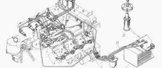
Engine oil circulation diagram
Engine oil from the sump is sucked by a gear pump and supplied to the filter.
Passing through the filter element, the oil is supplied through channels in the cylinder block and cylinder head to the crankshaft journals, cams and camshaft beds. The pressure in the lubrication system depends on the speed of rotation of the crankshaft. The minimum pressure is developed by the pump at idle, and the maximum is limited by the pressure reducing valve. To allow the driver to monitor the health of the system, an oil pressure sensor is mounted in the cylinder block, and sometimes in the cylinder head. On modern cars, only a few sports cars are equipped with a pressure gauge on the dashboard. On most cars they were replaced with a low pressure indicator, which lights up only when the pressure in the oil lines drops.
Purpose of SS car engine
An internal combustion engine is a complex complex of components and assemblies connected into a single whole and ensuring stable operation of the power unit. But since it contains many parts that rub at high speed, for their smooth functioning it is necessary to ensure reliable delivery of lubricant. This is what the lubrication system does: without it, the engine would not last even ten minutes. Running the power unit “dry” is fraught with rapid heating of the rubbing surfaces to a critical level, after which, due to thermal expansion, the gaps decrease, followed by destruction of engine parts subject to increased friction.
The difficulty in implementing an engine lubrication system is not only to ensure that the lubricant is delivered to the right place, although this is also a difficult engineering task, but also to ensure the circulation of engine oil in a closed cycle with minimal losses.
Here is a list of tasks solved through the use of SS:
- reduction of friction force due to the formation of a thin protective film on rubbing surfaces;
- cooling the surfaces of power unit parts;
- cleaning technical fluids from metal shavings and other solid contaminants on protected surfaces;
- ensuring uninterrupted circulation of lubricating fluid under the required pressure;
- preventing premature wear of SA parts.
Complication of design
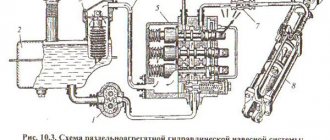
Using the example of a 2.5 liter diesel engine from VW, you can see how much more complex the operation of the lubrication system of a modern engine has become. Let's look at the purpose of each of the elements.
- Two-stage internal gear type oil pump. Installed in the oil pan.
- Oil pressure regulating valve. Using a solenoid valve, the ECU (Engine Control Module) directs oil to different channels, thereby switching the operating modes of the oil pump. When regulating performance, the engine load, coolant temperature, crankshaft speed and signals from the automatic transmission are taken into account. When a control signal is applied, the valve opens, allowing oil to flow into the channels of the first stage (the pressure in the system is about 1.8 atmospheres). In the absence of a control “mass”, the return spring returns the valve to its original position, changes the direction of oil flow, raising the pressure in the system to 3.3-4 Atm.
Changing the performance makes it possible to reduce the mechanical losses spent on lubrication and cooling of the engine’s rubbing pairs. This solution increases the overall efficiency of engines, reducing the amount of harmful emissions.
- Check valves in return lines. They allow lubricant to flow in only one direction and prevent complete drainage of oil from the channels after the engine is stopped. Filled channels allow you to avoid oil starvation in the first seconds after starting the engine.
- Safety valve. Opens during a cold start when excessive pressure develops in the system.
- Small circuit valve. Triggers when the filter element is clogged, opening the way for oil to bypass the filter.
- Oil cooler. Oil and coolant circulate through the heat exchanger housing.
- The cooler helps maintain the thermal balance of the engine and prevents oil overheating.
- Oil injector valve. It opens when the design pressure is reached in the system, opening the line to the injectors.
- Oil nozzle. Sprays oil onto the piston crown, removing heat from it.
- Pressure reducing valve. Triggers when excessive pressure is reached in the system, protecting the cylinder head from excess oil.
Purpose and characteristics
A lubrication system is a system that supplies oil to the rubbing parts of the engine. The lubrication system serves to reduce friction and wear of engine parts, to cool and provide corrosion protection to rubbing parts and to remove wear products from their surfaces.
Rice. 1. Types of lubrication systems classified according to various criteria
Car engines use a combined lubrication system of various types (Fig. 1). A combined lubrication system is a lubrication system that lubricates engine parts under pressure and splashing. The pressure is created by the oil pump, and oil is sprayed onto the crankshaft and other rapidly rotating engine parts. The most heavily loaded rubbing parts of engines are lubricated under pressure - the main and connecting rod bearings of the crankshaft, camshaft support bearings, oil pump drive shaft bearings, etc. Splashing lubricates the cylinder walls, pistons, piston rings, piston pins, parts of the gas distribution mechanism, its chain or gear drives and other engine parts. In engines with a lubrication system without an oil cooler, cooling of the oil, which heats up during operation, occurs mainly in the oil pan. If there is an oil cooler in the lubrication system, the oil is cooled both in the oil pan and in the oil cooler, which comes into operation when the vehicle is driven for a long time at high speeds and when the vehicle is operated in the summer. In a lubrication system with open crankcase ventilation, crankcase gases, consisting of a combustible mixture and combustion products, are released into the environment. When the crankcase ventilation is closed, crankcase gases are forcibly removed into the engine cylinders to burn out, which prevents gases from entering the passenger car interior and reduces the release of toxic substances into the environment. To lubricate car engines, special motor oils of mineral origin are used, which are obtained from petroleum, as well as synthetic ones. Brands of motor oils are very diverse. Their main properties are viscosity, oiliness and purity (absence of mechanical impurities and acids). Viscosity characterizes the purity of the oil, its fluidity and ability to penetrate into the gaps between rubbing parts. Oiliness characterizes the ability of oil to envelop rubbing parts with an oil film. To improve the quality of motor oils, special additives are added to them to increase the lubricating properties of the oils.
Oil pump
Among the various types of design, gear and rotary oil pumps are the most widely used. Design of an external gear type oil pump:
- Driven gear.
- Oil intake channel from the sump.
- Drive gear. It is this that is connected to the engine crankshaft through a worm, chain or gear transmission.
- Drive shaft (in this type of oil pump, connects the crankshaft and the drive gear).
- Discharge channel.
- Rotation axis of the drive gear.
When the gears rotate, oil is sucked from the intake channel and supplied through the discharge channels to the rubbing steam of the engine. Oil pressure in the lubrication system and pump performance are directly related to the crankshaft speed. When the pressure exceeds sufficient to lubricate and remove heat from the rubbing elements, the excess lubricant is released by the pressure reducing valve.
Unlike an external gear pump, internal gear pumps have a drive gear that rotates inside the driven gear. The principle of operation of the lubrication system in terms of pressure injection remains unchanged and is similar to the operation of a rotary pump. External and internal rotors are installed inside the housing. The rotation of the latter leads to the suction of lubricant and its supply under pressure into the discharge channel.
MAIN FAULTS
The design of the oil pump, no matter what type it is, is relatively simple, which ensures its reliability and long service life. And yet it does have faults, or rather there is only one – a decrease in productivity, which leads to a drop in pressure in the system. And this can lead to more serious damage, since components that are not sufficiently lubricated begin to wear out intensively due to oil starvation. This can happen for various reasons.
- The first of these does not apply to the pump, but leads to negative consequences in its operation - clogging of the oil receiver mesh with wear products and dirt. As a result, insufficient oil flows to the pump. It is not difficult to fix such a malfunction - just remove the pan and oil receiver, then thoroughly clean and rinse the mesh.
- The problem with pressure drop can occur due to wear of the pump components or prolonged operation with oil that contains a large number of contaminants. The result of this is the formation and increase of gaps between pump parts. Because of this, the lubricant simply flows through these gaps inside the injection cavity and the gears or rotors are not able to capture it in order to pump it into the line. In most cases, the performance of the lubrication system is restored by replacing worn elements or the assembly as a whole.
- The bypass valve can also create problems. Due to dirt, it can jam in the open position, and oil will constantly flow into the pan. This malfunction can be eliminated by disassembling and washing the pump and its channels.
Pressure reducing valve
Since the performance of unregulated pumps directly depends on the engine speed, the maximum safe oil pressure in the lubrication system is maintained by a pressure reducing valve. It is a shut-off valve supported by a return spring. When the calculated oil pressure at the valve side overcomes the spring force, the valve opens, releasing excess oil back into the oil pan.
Staffing table
For any engine, the lubrication system includes:
- oil container (crankcase or separate tank);
- an oil receiver, which is an intake neck with a filter mesh to separate large foreign particles;
- lubrication pump;
- replaceable filter;
- pressure reducing valve (one or more);
- pressure meter;
- main pressure line and channels, usually integrated into parts of the power plant;
- dipstick for monitoring the lubricant level.
Additionally, the lubrication equipment may include: a temperature sensor, a level sensor, and lubricating nozzles. Sometimes the engine has an oil cooler. The capacity of the lubrication system of a passenger car depends on the type of power plant and its dimensions. Typically, the volume of oil poured is from 3.5 to 7.5 liters.
Two Stage Oil Pumps
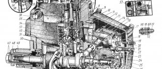
Let's consider the design of a two-stage oil pump using the example of a rotary-type unit from the VAG automaker.
- The first stage of operation is determined by the designers, based on the volume of oil required by the engine in all operating modes. From the injection cavity, oil is directed into the engine channels and to the movable rotor where it rests on the adjusting plate. In this mode, the volume of the suction cavity and, as a result, the amount of pumped oil is small.
- Second stage. As engine speed increases, the need for more lubricant arises. The pressure on the moving rotor weakens. Now the adjusting spring rotates the stator a few degrees, changing the position of the driven rotor. This increases the volume of the suction cavity and the amount of lubricant pumped.
In FSI Audi engines of 2.8 and 3.2 liters, the transition from the first to the second stage occurs at crankshaft speeds above 4600. Thanks to two-stage pumps, the designers managed to reduce fuel consumption by 1/3.
Question 37 General structure and principle of operation of a four-stroke internal combustion engine.
The engine consists of a cylinder 5 and a crankcase 6, which is covered from below by a pan 9 (Fig. a). A piston 4 with compression (sealing) rings 2 moves inside the cylinder, having the shape of a glass with a bottom in the upper part. The piston, through piston pin 3 and connecting rod 14, is connected to the crankshaft 8, which rotates in the main bearings located in the crankcase. The crankshaft consists of main journals 13, cheeks 10 and a connecting rod journal 11. The cylinder, piston, connecting rod and crankshaft make up the so-called crank mechanism, which converts the reciprocating movement of the piston into the rotational movement of the crankshaft
. The position of the piston in the cylinder at which its distance from the axis of the engine shaft reaches a maximum is called top dead center (TDC). Bottom dead center (BDC) is the position of the piston in the cylinder at which its distance from the axis of the engine shaft reaches a minimum.
. The volume of the cylinder formed by the piston when it moves between dead points is called the working volume of the cylinder Vh.
Figure 1.2 . Diagram of a piston internal combustion engine
Engine displacement is the product of the cylinder displacement times the number of cylinders.
The ratio of the total volume of the cylinder Va to the volume of the combustion chamber Vc is called the compression ratio
The operating cycle is a set of sequential processes carried out to convert the thermal energy of fuel into mechanical energy.
A)
b)
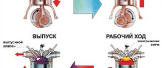
Rice. 1.3. Engine duty cycle diagrams
Operating cycle of a four-stroke internal combustion engine
An engine whose operating cycle is completed in four strokes, or two revolutions of the crankshaft, is called four-stroke. The operating cycle in such an engine occurs as follows. The working cycle of a 4-stroke carburetor internal combustion engine is completed in 4 piston strokes (stroke), i.e. in 2 revolutions of the crankshaft. During the 1st stroke - intake, the piston moves from top dead center (TDC) to bottom dead center (BDC). The intake valve is open and the combustible mixture from the carburetor enters the cylinder. During the 2nd stroke - compression, when the piston moves from n. m. t. sq. m.t., the inlet and outlet valves are closed and the mixture is compressed to a pressure of 0.8-2 MN/m2 (8-20 kgf/cm2). the temperature of the mixture at the end of compression is 200–400°C. At the end of compression, the mixture is ignited by an electric spark and fuel combustion occurs. Combustion takes place when the piston position is close to c. mt. At the end of combustion, the pressure in the cylinder is 3-6 Mn/m2 (30-60 kgf/1cm2), and the temperature is 1600-2200°C. The 3rd stroke of the cycle—combustion and expansion—is called the power stroke; During this stroke, the heat obtained from fuel combustion is converted into mechanical work. 4th stroke - release occurs when the piston moves from N. m. t. to v. m.t. with the outlet valve open. The exhaust gases are displaced by the piston.
Working process of four stroke diesel engine
includes the following steps:
1. Intake stroke. When the piston moves, a vacuum is formed in the cylinder and atmospheric air enters its cavity through the air filter. In this case, the inlet valve is open.
2. Compression stroke. The piston moves, compressing the incoming air. For reliable ignition of fuel, it is necessary that the temperature of the compressed air be higher than the auto-ignition temperature of the fuel. The intake and exhaust valves are closed.
3. Expansion stroke (or power stroke). The fuel injected at the end of the compression stroke, mixed with heated air, ignites, and the combustion process begins with a rapid increase in temperature and pressure. At this moment both valves are closed. Under the influence of gas pressure, the piston moves, thereby performing useful work.
4. Release stroke. The piston moves upward, pushing exhaust gases into the exhaust manifold, the temperature of which decreases.
Rice. 1.4. Inlet Fig. 1.5. Compression
Rice. 1.6. Expansion Fig. 1.7. Release
Valve N428
The oil pump control valve N428 is designed to regulate the pressure on the control piston. Depending on the pressure on the piston, the position of the stator and the volume of the suction chamber changes. Part of the oil from the discharge cavity is always supplied to the control line to valve N428. At the command of the engine control unit, power is supplied to the valve and oil is supplied to the control piston. By design, the N428 is an electrically controlled hydraulic 3/2 way valve.
Principle of operation
Since individual engine parts operate under different conditions, their lubrication should also be different.
Oil is supplied to the most loaded parts under pressure, and to less loaded parts - by gravity or splashing. Systems in which parts are lubricated in different ways are called combined. When the engine is running, the oil pump ensures continuous circulation of oil throughout the system. Under pressure, it enters the oil filter, and then to the main and connecting rod bearings of the crankshaft, piston pins, camshaft supports and cams, and the axis of the valve drive rocker arms. Depending on the design of the engine, oil is supplied under pressure to the turbocharger shaft, to the inner surface of the pistons for cooling, to the valve lifters and actuators of the phasing systems.
Oil reaches the cylinder surfaces by splashing through holes in the lower connecting rod head or nozzles in the lower part of the cylinder block. Getting on the cylinder walls, it reduces friction during piston movement and ensures freedom of movement of compression and oil scraper rings.
Drops of oil fall from pressure-lubricated parts into the sump. When they fall on the rotating parts of the crank mechanism, they splash, creating so-called oil mist in the crankcase. By settling on engine parts, it provides lubrication. The precipitated oil then drains into the oil pan and the cycle repeats.
The difference between a wet sump and a dry sump
Above, we considered an exclusively wet sump, when the main volume of the engine lubrication system is in the sump and is taken from there by an oil pump.
The diagram shows the parts and instruments of the lubrication system of a dry sump engine. The main difference is that the engine sump is not used to store oil. All lubricant that has flowed there is pumped out by a special pump and supplied to a separate tank. From there, pressure in the oil system is created using a pressure pump. This engine lubrication system is used in off-road vehicles and racing cars. Main advantages:
- The height of the tray is reduced, which allows you to install the motor lower. Lowering the center of mass improves the vehicle's directional stability and handling;
- a dry sump eliminates oil starvation when the car moves at large longitudinal and transverse angles, which is important for SUVs on rough terrain;
- oil starvation due to the loss of lubricant (flow from one part to another) during prolonged movement of the car in an arc is excluded, which is important for circuit racing and drifting competitions;
- Engine oil cools better.
But the system is not without its drawbacks, since increasing the complexity of the system reduces reliability and increases the weight of the vehicle.
Video: Lubrication system of an internal combustion engine (ICE) in 3D. How does it work?
Oil pressure diagnostics.
The oil pressure light comes on at idle speed. This is the first alarming symptom. But all may not be lost. The cause of low engine oil pressure can be very simple and easily fixed.
The farthest point from the oil pump is the engine block head. Naturally on the rocker arms or on the camshaft if it is located in the cylinder head. The lowest pressure is formed. But for normal engine operation it must be present. Therefore, even if you just open the filler plug in the valve cover. The head parts are thoroughly lubricated. When the engine is running, oil splashes will be visible. If they are not there, it means the oil is coming in at low pressure. And even from this fact one can judge that there is a malfunction in the oil system. And you can already judge why the oil pressure light came on.
But it could also be that the oil pressure sensor is faulty. The light comes on. and the parts of the block head are generously lubricated. You can simply try replacing the sensor. But it will be more correct if you measure the pressure using a mechanical pressure gauge.
You need to find where the oil pressure sensor is located. Unscrew it. Install a mechanical pressure gauge in its place. It will accurately show the oil pressure in the oil system. Oil pressure is below 0.2 Nm at idle speed. Indicates that there is a malfunction.
Any malfunction in the engine must begin with removing the pan. First of all, of course, you need to make sure that the oil receiver and the connection points with the pump are in good condition. No cracks, dirt, condition of seals. If everything is ok. The bearings of the main and connecting rod journals of the crankshaft are checked. This can be done using calibrated plastic wire. The cap of the main and connecting rod bearings is unscrewed and a plastic wire is placed between the crankshaft journal and the liner. The cover is tightened with the force intended for this engine model. The cover is removed again. And by the width of the resulting spot one can judge the size of the resulting gap. It should not exceed more than 0.15 mm. This measurement can be called conditional. Because the crankshaft journal does not wear evenly. The wear forms an oval. Along the cross section of the shaft journal. Therefore, this measurement can give a rough idea of wear. And conditionally exclude or confirm the cause of the malfunction. In order to move further in troubleshooting.
Problems with the lubrication system
- mechanical wear of oil pump parts. Occurs due to untimely replacement of the oil or filter element. When wear occurs, sufficient vacuum is not created in the suction zone, which causes a decrease in pump performance;
- coking and clogging of the oil receiver with foreign objects. Happens when the oil is not changed in a timely manner, the plastic elements of the tensioning and calming shoes are destroyed;
- pressure reducing valve hanging;
- electrical fault or wiring problems with the two-stage pump control valve;
- failure of the oil pressure sensor, which causes the low pressure warning light to light up on the dashboard;
- jamming of the check valve in the return lines;
- failure of the oil pressure indicator;
- jamming of the oil thermostat, which is used to warm up the lubricant more quickly.
The modern lubrication system consists of many mechanical and electronic components, as a result of which its reliability has significantly decreased. Therefore, it is extremely important to monitor compliance with service intervals, the quality of filters and engine oil.
Seal
Choosing engine oil
The main task of motor oil is to prevent dry friction of the moving internal parts of the engine, as well as to ensure minimal friction force with maximum tightness of the working cylinders.
Based on the requirements of the engine of a particular car and the ambient temperature, motor oil is selected according to two main criteria: - the level of performance properties according to the API or ACEA classification, which must meet the requirements of your engine; — viscosity according to SAE classification, which is selected depending on the ambient temperature and the degree of engine wear.
One of the main properties of motor oil is its viscosity and its dependence on temperature over a wide range (from the ambient air temperature at the time of cold start in winter to the maximum temperature in the engine at maximum load in summer). The most complete description of the compliance of the viscosity-temperature properties of oils with engine requirements is contained in the internationally accepted classification SAE3000.
Conclusion
The lubrication system plays a vital role both in the operation of the entire vehicle and the engine itself. It allows you to constantly irrigate the internal components of the “heart of the machine,” which are subject to enormous loads and wear out from high temperatures and friction. Thus, all engine components will last as long as possible and with the least wear.
and in engine operation. It allows you to constantly irrigate the internal components of the “heart of the machine,” which are subject to enormous loads and wear out from high temperatures and friction. Thus, all engine components will last as long as possible and with the least wear.